AKO-555241 Gas Leak Detection and Trapped Person Alarm User Manual
AKO Electromecánica thanks and congratulates you for purchasing our product, in whose development and manufacture the most innovative technology has been used, as well as strict production and quality control processes.
Our commitment to satisfy our customers and our continuous efforts to improve every day can be seen in the various quality certifications we have obtained.
This is a high performance, high technology product. The operation and final performance of the equipment depend on proper planning, installation, configuration and commissioning. Read this manual carefully before installation, and always follow its instructions.
Only qualified personnel should install or perform technical assistance on this product.
This product is designed to be used in the applications described in the product manual. AKO Electromecánica gives no guarantee of its operation in any use not foreseen in the manual, and is not responsible for any damage resulting from improper use, configuration, installation or commissioning.
It is the responsibility of the installer and the customer to comply with and ensure others comply with all regulations applicable to installations incorporating our products. AKO Electromecánica is not responsible for any damage caused by non-compliance with regulations.
Follow strictly the instructions given in this manual.
To maximise the service life of our equipment, these recommendations should be followed:
Do not expose electronic equipment to dust,dirt,water,rain, humidity, high temperatures,chemicals or corrosive substances of any sort.
Do not submit the equipment to blows or vibrations nor try to manipulate it differently from shown in the manual.
Never exceed the specifications and limitations indicated in the manual.
Always respect the specified ambient working and storage conditions.
During and after installation, avoid leaving loose, broken, unprotected or damaged wiring, since they might constitute a risk for the equipment and its users.
AKO Electromecánica reserves the right to make any non-metrology modification to the documentation or the equipment without previous notice
Versions and references
| MODEL | DESCRIPTION | BATTERY | POWER SUPPLY |
| AKO-555241 | Alarm Station with 2 channels | YES | 100-240 V~ 50/60 Hz |
| AKO-558241 | Alarm Station with 2 channels | NO | |
| AKO-555242 | Alarm Station with 4 channels | YES | |
| AKO-558242 | Alarm Station with 4 channels | NO | |
| AKO-575xxx | Gas transmitter | NO | 12 – 30 Vdc |
| AKO-5761X | Gas detector (Semiconductor) | NO | 12 – 30 Vdc |
| AKO-55326 | Luminous push-button | NO | – |
| AKO-58110 | Calibration tool for transmitters | – | – |
| AKO-58120 | Protector for push-button / transmitter / detector | – | – |
AKO-555241 / 558241
AKO-555242 / 558242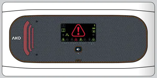
AKO-55326
AKO-575xxx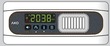
AKO-5761x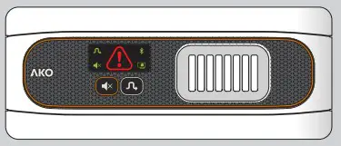
AKO-58120
AKO-58110
| TRANSMITTER | GASES DETECTED | PRE-ALARM | ALARM |
| AKO-575022 | R-22 | Configuration dependent | Configuration dependent |
| AKO-575134A | R-134A | ||
| AKO-575404A | R-404A | ||
| AKO-575410A | R-410A | ||
| AKO-575507A | R-507A | ||
| AKO-575400 | R-134A, R-404A, R407A, R-410A, R-125, R-448A, R-449A, R-407F |
| DETECTOR | GASES DETECTED | DEFAULT LEVELS | 2 SET OF LEVELS | ||
| PRE-ALARM | ALARM | PRE-ALARM | ALARM | ||
| AKO-57613 | R-717 (NH / ammonia) | 500 PPM | 1000 PPM | – | – |
| AKO-57614 | R-134a, R22, R-404A, R-407A, R-407C, R-407F, R-409A, R-408A, R-410A, R-422A, R-422D, R-424A, R-434A, R-442A, R-448A, R-449A, R-450A, R-452A, R-453A, R-507A, R-513A | 500 PPM | 1000 PPM | 1500 PPM | 3000 PPM |
| AKO-57615 | R-744 (CO ) | 4000 PPM | 8000 PPM | 5000 PPM | 10000 PPM |
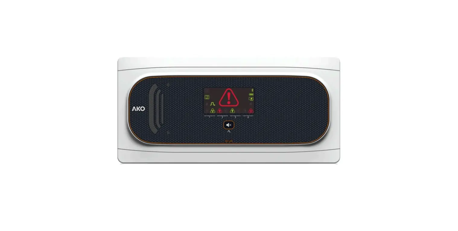
Equipment description
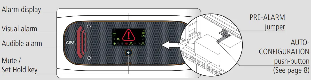
AKO-555242 / AKO-558242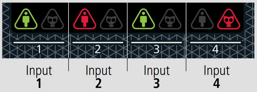
 Constant green: Trapped person push-button connected.
![]() Quick-flashing red: Malfunction / wiring fault in push-button.
Quick-flashing red: Malfunction / wiring fault in push-button.
Slow-flashing red: Push-button not detected or disconnected.
Constant red: Trapped person alarm activated.
 Green constant: Gas transmitter / detector connected.
Flashing green: Gas pre-alarm / alarm saved
 Quick-flashing red: Malfunction / wiring fault in gas transmitter / detector.
Slow-flashing red: Gas transmitter / detector not detected or disconnected.
Constant red: Gas pre-alarm / alarm activated.
 Constant: Gas pre-alarm / alarm / trapped person alarm activated.
Flashing: Malfunction / wiring fault in detector / transmitter / pushbutton.
 Constant: Set Hold mode activated
Flashing: Maintenance mode activated
![]() Power supply present
Power supply present
![]() Bluetooth activated (Only with CAMM module)
Bluetooth activated (Only with CAMM module)
![]() Constant green: Battery connected
Constant green: Battery connected
Switched off: Battery disconnected *
 Constant: CAMM module in operation
Flashing: CAMM module malfunction
. Gas alarm silenced
 Pressing for 3 seconds activates / deactivates the Set Hold mode.
Pressing for 6 seconds activates / deactivates the maintenance mode.
Pressing briefly deletes saved alarms.
For gas alarm, pressing briefly silences the alarm tone
Trapped person alarms cannot be silenced.
AKO-558xxx models are not equipped with batteries.
Warnings
- Transmitters / detectors measure gas concentration at a given point. If the gas leak does not reach the transmitter / detector, the alarm will not be activated.
- Transmitters / detectors cannot supervise areas. If perimeter supervision is required, several transmitters / detectors should be installed surrounding the area to be supervised.
- Thoroughly studying transmitters’ / detectors’ location is recommended, bearing in mind the areas most vulnerable to suffering leaks, the type of gas used, the size and shape of the room, air flows, maintenance work, etc.
Maintenance
- Clean the device surface with a soft cloth, water and soap.
- Do not use abrasive detergents, petrol, alcohol or solvents, as this might damage the sensor.
![]() The EN-378 and F-GAS international standards require that correct transmitter / detector functioning be checked at least once per year. Review what current local regulations specify for these cases. Consult the appropriate verification method in the transmitter / detector manual.
The EN-378 and F-GAS international standards require that correct transmitter / detector functioning be checked at least once per year. Review what current local regulations specify for these cases. Consult the appropriate verification method in the transmitter / detector manual.
Be sure to always comply with current local regulations
Installation
WARNINGS
- The alarm and the transmitters / detectors should be installed in a place protected from vibrations, water and corrosive gases, where the ambient temperature does not exceed the value indicated in the technical data.
- The station should be installed in a monitored area, where it is guaranteed that people able to alert to the presence of alarms will be present.
- Neither the alarm nor the gas transmitter / detector are suitable for areas classified as potentially explosive.
- Transmitters / detectors monitor a point and not an area. If a gas leak does not reach the sensor, or if the concentration level at that point does not reach the predicted values for the gas type, no alarm will be activated.
Work conditions:
- Avoid handling refrigerant gases near the transmitter / detector.
- Do not paint the transmitter / detector or place it near solvents or paints.
- Exposure to acetone vapours may cause false alarms.
- The transmitter / detector should be installed away from:
- Smoke outlets located in or originating from engines, generators or motorised machinery (fork-lift trucks, etc.).
- Particularly damp areas or with strong ventilation.
- Remove the bezels (1) from the device.
- Loosen the screws (2) with a 1/4 turn and open the cover (3).
- Drill the holes needed for the cable entry glands using the pre-stamped centres on the sides of the housing for guidance. Fix the glands onto the device (4 and 5).
- Make 3 holes in the wall with the aid of the template included.
- Fix the device to the wall using the screws and plugs supplied (6).
- Insert the cables into the glands and wire the device following the diagram.
- Connect the battery (7) before closing the cover *..
- Close the cover (3), insert and tighten the screws (2) and replace the bezels (1).
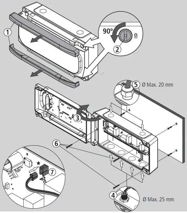
AKO-558xxx models are not equipped with batteries.
Wiring
 The wiring between the transmitter / detector / push-button and the station should NEVER be installed in a conduit alongside power,control or supply cables.
Always disconnect the power supply to carry out wiring.
For disconnection, the power supply circuit must be equipped with a switch of at least 2A, 230 V, located near the device. The power supply cable will be H05VV-F or NYM 1×16/3. The section to be used will depend on 2 current local regulations, but should never be less than 1.5 mm .
Cables for wiring the relay contact should have the relevant section for the device to be connected.
The 120 / 230 V~ wiring must be kept clear of any other external element
Make sure you have connected the batteries before starting up the device *.
Certain international standards indicate that alarm power supply should originate from a different circuit to that used for the refrigeration and ventilation system. Be sure to comply with current local regulations
AKO-558xxx models are not equipped with batteries.
Configuration
Input auto-detection
Step 1
When receiving a power supply for the first time, the alarm enters INPUT AUTO-DETECTION MODE, lighting up the input indicators sequentially in green.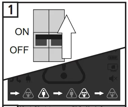
Step 2
Begin AUTO-DETECTION by pushing the ‘AUTOCONFIG’ push-button for 5 seconds (See page 4). At the end of the process, the alarm will emit 5 short beeps and will begin to function normally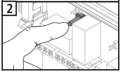
![]() For correct input detection, all devices must be correctly connected and in NO ALARM mode, including the pushbuttons connected in digital inputs.
For correct input detection, all devices must be correctly connected and in NO ALARM mode, including the pushbuttons connected in digital inputs.
 Once the alarm has been configured, this function will not be activated again. To activate it again, disconnect the power supply, connect it again and press the “AUTOCONFIG” pushbutton 5 times consecutively within 2 minutes and repeat step 2 within another 2 minutes.
Self-diagnosis function
The device incorporates a self-diagnosis system which informs the user in the event of a transmitter / detector / push-button malfunction or if there are wiring errors.
If a malfunction is detected, the alarm will emit 3 short beeps every 2 minutes and the corresponding input indicator will flash red.
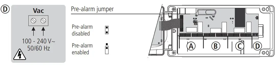
Pre-alarm jumper
It allows deactivating pre-alarm detection. Before using this option, make sure that regulations allow for only one alarm level.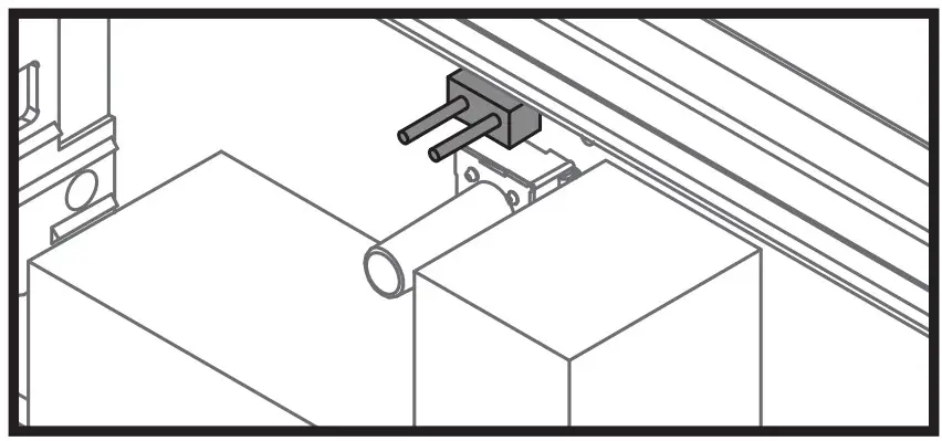
- Pre-alarm enabled
- Pre-alarm disabled
![]() When using the ammoniac or CO2 transmitter / detector, the pre-alarm must be enabled.
When using the ammoniac or CO2 transmitter / detector, the pre-alarm must be enabled.
Operation
No alarms
The input indicators are green.
Pre-alarm / alarm activated
The station emits an audible alarm sound, shows the affected input(s) in red, the general alarm indicator illuminates and the visual alarm flashes.
Wiring error / malfunction
The station emits 3 short beeps every two minutes and the affected input indicator flashes red.
Short-circuit detection in an input
If a short-circuit is detected in any given input, this input will be deactivated and the indicator corresponding to the affected input will flash red. The general alarm indicator will also flash.
Once the problem has been resolved, to re establish functioning f the affected input, press the Mute button for more than 1 second.
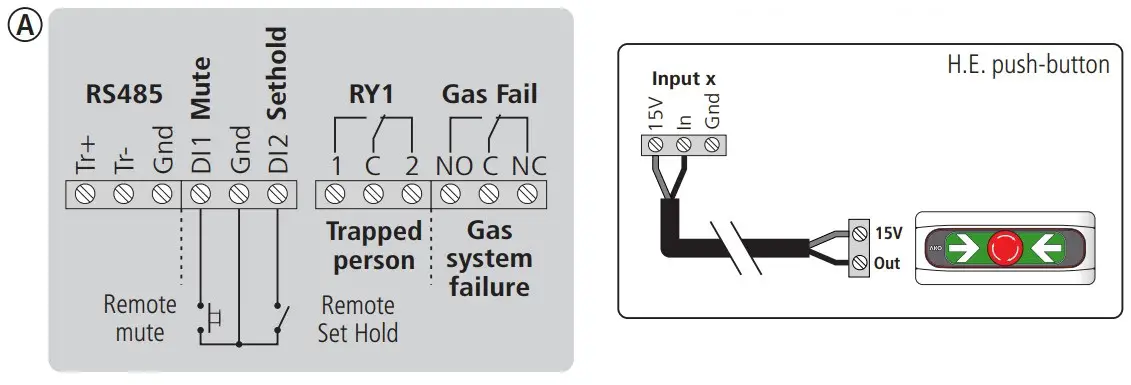
MUTE Function
Allows for the sound of gas pre-alarms and alarms to be silenced. Does not affect relay or indicator functioning.
To activate it, press the Mute button at any point when a pre-alarm or alarm is activated. The display shows the silenced alarm indicator ![]() .
.
Optionally, it can also be remotely activated using a push-button connected to digital input 1 (DI1).
If a pre-alarm is silenced, this function will be voided by changing to an alarm or if a new pre-alarm or alarm is activated.
![]() Trapped person alarms cannot be silenced.
Trapped person alarms cannot be silenced.
Gas alarm saved
Indicator ![]() flashes green to indicate that a gas pre-alarm or alarm has sounded in our absence. To delete it, press the mute button.
flashes green to indicate that a gas pre-alarm or alarm has sounded in our absence. To delete it, press the mute button.
Set Hold Mode
Avoid false alarms during the chamber charging or cleaning process.
When this mode is activated, pre-alarms will not sound and alarms will sound like pre-alarms to all effects (sound, relay and signal activation).
To activate / deactivate it, press the Mute key for 3 seconds; the display will show indicator ![]() .
.
Optionally, it can also be remotely activated / deactivated using a switch connected to digital input 2 (DI2).
This mode will remain activated for a maximum of 5 hours, before automatically deactivating itself.
If it is activated using the Mute key, it will only be able to be deactivated using the same key. The same applies to activation using digital input 2.
This mode does not affect trapped person alarms.
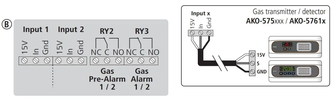
Gas Relay Fail
This relay will be activated if a functioning error is detected in any input with connected gas transmitters / detectors. Connecting a GSM to it is recommended, to remotely warn of the fault.
Maintenance Mode
Disables gas pre-alarms and alarms for 1 hour for maintenance tasks.
When it is activated, no gas pre-alarm or alarm will sound.
To activate / deactivate it, press the Mute key for 6 seconds; indicator  will flash.
Power supply indicator
ALARM STATION
| STATUS |  | Relays (without activated alarms) | ||||
| Trapped person | Gas system failure | Gas Pre-alarm 1 / 2 | Gas Alarm 1 / 2 | |||
| With power supply Battery connected * | |  |  |  | | |
| With power supply Battery disconnected * | | | | | | |
| No power supply / With battery * |  | | | | | |
| No power supply/ No battery | |  |  | | | |
AKO-558xxx models are not equipped with batteries.
In the event of a power failure, the gas detectors will disconnect to extend battery duration and the corresponding indicator will switch off on the display.
Trapped person alarm inputs will continue to operate until their batteries run flat.
Trapped person alarm
ALARM STATION
| STATUS |  |  |  |  | Relays | |
| Trap. person | Gas sys. failure | |||||
 | OFF |  | 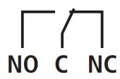 | |||
 |  | Bi-tonal sound |  | | ||
| Transmitter / detector / wiring fault |  * * |  | 3 short beeps every 2 minutes | | | |
Gas leak detection alarm
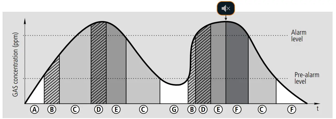
| STATUS | | | | | Relays | ||
| Pre-alarm | Alarm | Sys. failure | |||||
| A No alarm | | OFF | | | | ||
| Pre-alarmB delayed | | Bi-tonal sound | | | | ||
| C Pre-alarm | | | Intermittent sound | 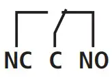 | | | |
| D Alarm delayed | | | Intermittent sound | | | | |
| E Alarm | | | Bi-tonal sound | | | | |
| F Alarm silenced | | | OFF | | | | |
| G Alarm saved |  * * | | | OFF | | | |
| Transmitter / detector / wiring fault |  * * | | 3 short beeps every 2 minutes | | | | |
The input indicator corresponding to the activated push-button will turn on.
Connectivity
The transmitters are equipped with a port for connection of RS485 (MODBUS) data, allowing it to remotely manage data using an AKO-5012 web server.
The MODBUS address is factory-set and is indicated on the rating plate located on the left side of the alarm. This address must be different for each device within the same network. The address can be modified using the b20 parameter. Once modified, the original address indicated on the plate will no longer be valid.
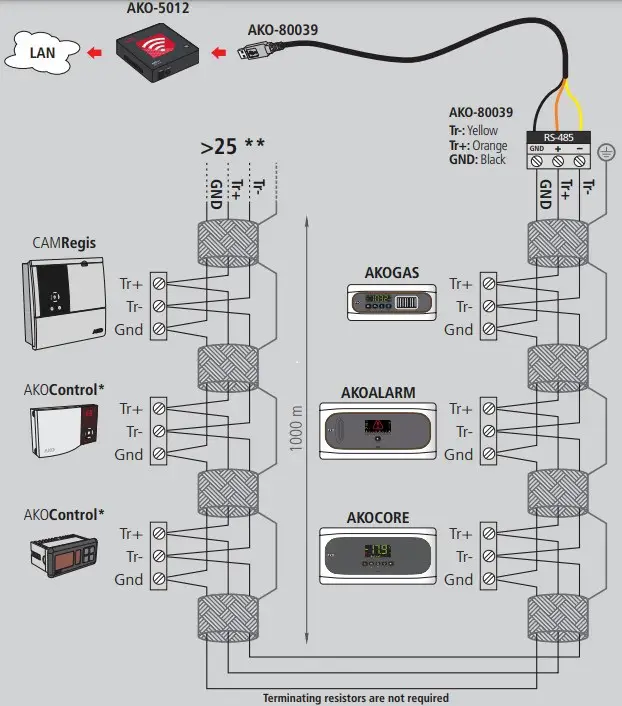
*AKO controller with communication
**AKO-80024 Use if connecting more than 25 devices
Technical specifications
AKO-555241 / AKO-558241 / AKO-555242 / AKO-558242
Power supply ……………………………………………………………………………100-240 V~ 50/60 Hz
Maximum input power………………………………………………………………………….15 W
Accumulators (Only AKO-555xxx)…………………………………………………Ni-MH 1.6 Ah
Lighting + alarm autonomy (Only AKO-555xxx) ……………………………….> 10 Hours (*)
No. of inputs AKO-555241 / AKO-558241…………………………………………………………………..2
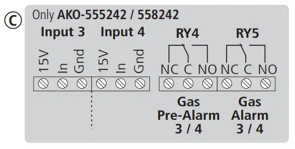
AKO-555242 / AKO-558242……………………………………………………………………4
Compatibility of inputs …………………………………………………………AKO-55326 push-button ……………………………………AKO-575xxx transmitter …………AKO-5761x detector
Relays……………………………………………………………………………………..SPDT 8(2)A 250 V~
Working ambient temperature…………………………………………………………..-5 ºC to 50 ºC
Storage ambient temperature …………………………………………………………………..-30 ºC to 60 ºC
Protection degree ………………………………………………………………………………………..IP 65
Installation category ……………………………………………………………………….II s/ EN 61010-1
Pollution degree ………………………………………………………………………….II s/ EN 61010-1
Double isolation between power supply, secondary circuit and relay output.
Sound power………………………………………………………………………………………90 dB(A) at 1 metre
MODBUS address……………………………………………………………………………….Shown on label
Maximum push-button cable distance ………………………………………………………….300 m
Dimensions……………………………………………..290 mm (W) x 141 mm (H) x 84.4 mm (D)
Accessories
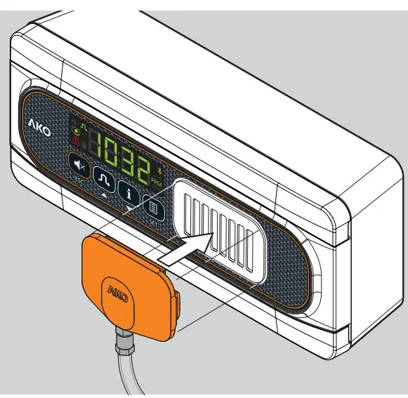
Calibration tool for AKO-58110 transmitters
Allows for verification (bump test), field calibration and reset to zero of AKO-575xxx gas transmitters.
*Duration in alarm status at an ambient temperature of between 25 ºC.
AKO-58120 Protector
Protects the AKO-55326 push-button / AKO-575xxx gas transmitter / AKO-5761x gas detectors from potential impact.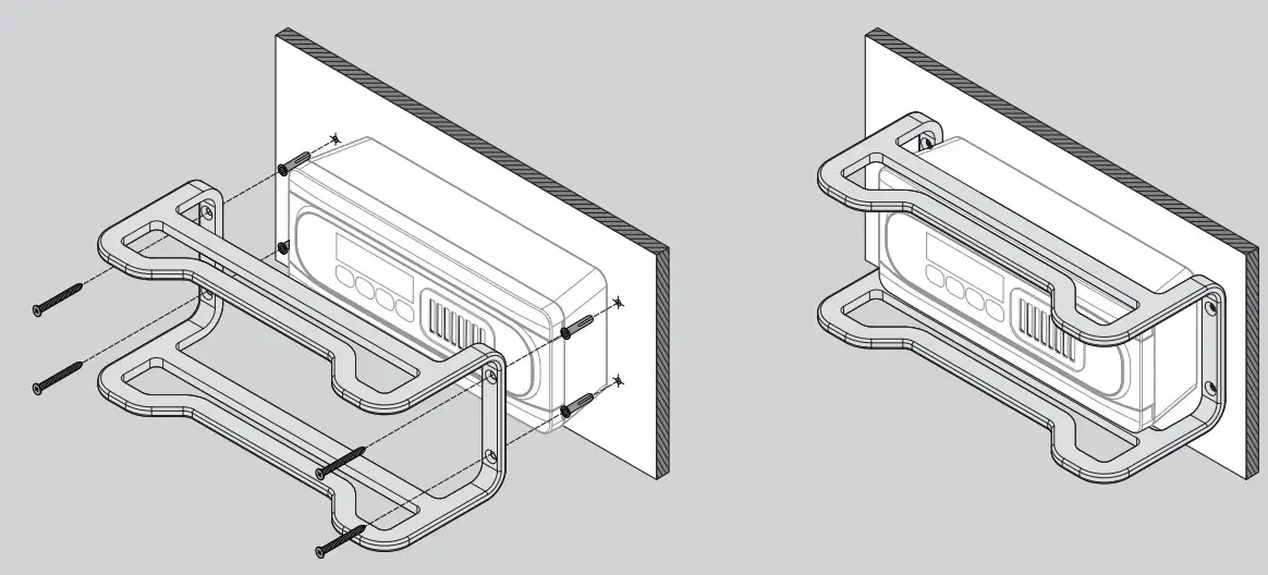
AKO ELECTROMECÁNICA , S.A.L.
Avda. Roquetes, 30-38
08812 • Sant Pere de Ribes.
Barcelona • Spain.
We reserve the right to supply materials that might vary slightly to those described in our Technical Sheets.Updated information is available on our website.