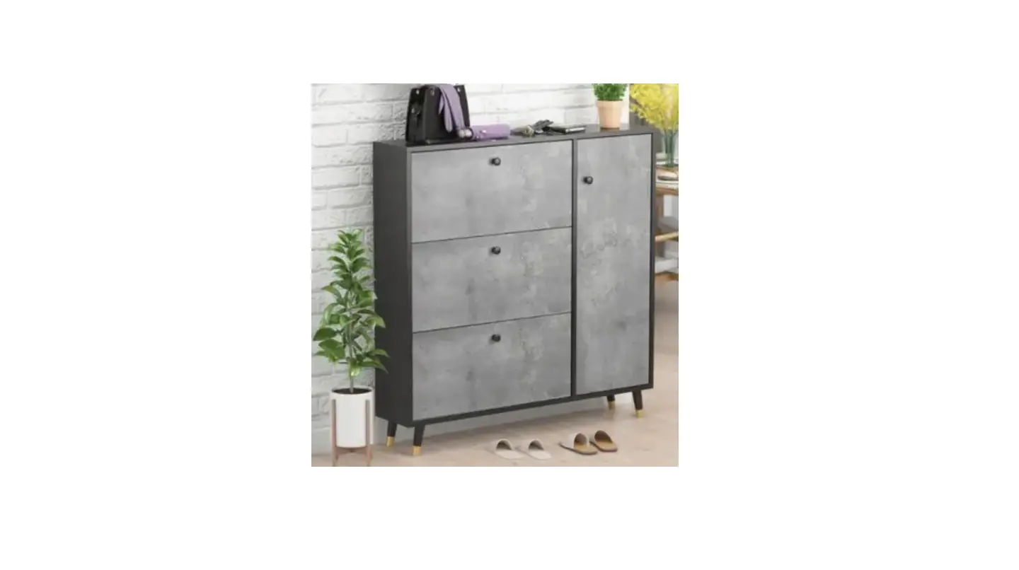
FUFU GAGA KF210119-01 18 Pair Gray Composite Shoe Cabinet Installation Guide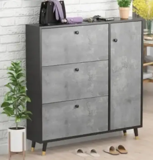
![]() Warning
Warning
- Vnit can tip over causing severe injury or death.
- Anchor unit to stud in wall (i£ instructed to).
- Do Not allow children to climb on unit.
- Put heavy items on lower shelves or drawers.
Assembly instruction
Helpful Hints
- Open your item in the area you plan to keep it to avoid excessive heavy lifting.

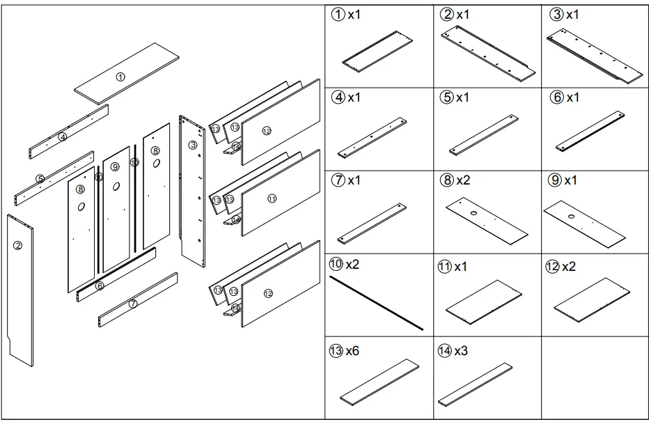
- Identify, sort and count the parts be£ore attempting assembly.

- Compression dowels are lightly tapped in with a hammer.

- Slides are labeled with a R (right) and L (le£t) £or proper placement.

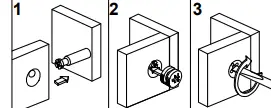
- Make sure to always £ace the point on the top o£ the Cam Lock towards the outer edge.

- Vse all the nails provided £or the back panel and spread them out equally.

- Back panel must be used to make sure your unit is sturdy.
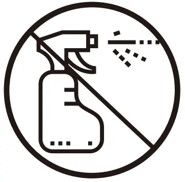
- Do NOT use harsh chemicals or abrasive cleaners on this item.
- Never push, pull, or drag your Furniture.


Before You Start
- Read through each step carefully and follow the proper order
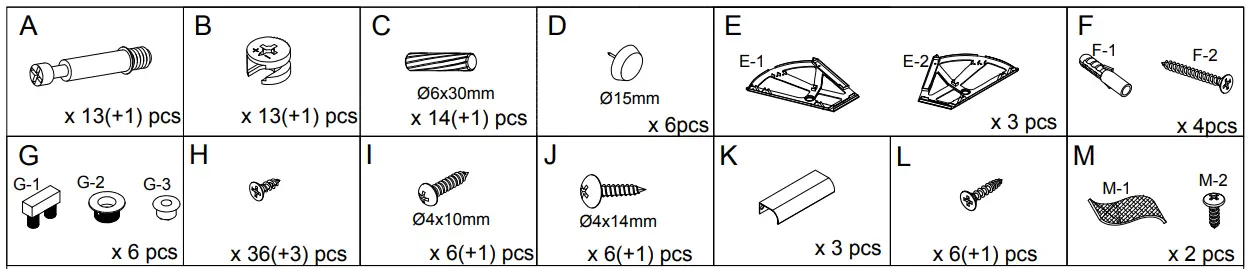
- Separate and count all your parts and hardware
- Give yourself enough room for the assembly process
- Have the following tools: Hammer
- Caution: If using a power drill or power screwdriver for screwing, please be aware to slow down and stop when screw is tight.
Failure to do so may result in stripping the screw.
Installation instruction
Assembly instruction
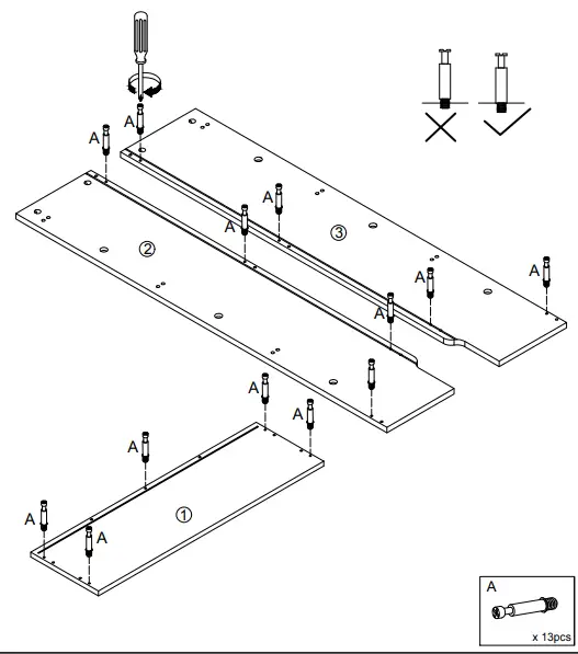
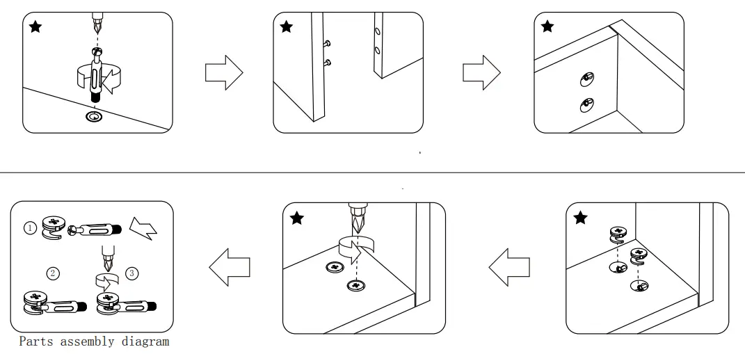
- Tighten Cam Bolt (A) to panel 2 , panel 3 and panel 1

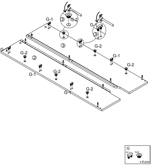
- Please hammer the G-1 and G-2 onto the 2 and 3 boards

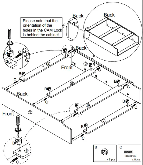
- Please turn No. 2 board and No. 3 board behind, INSERT SAWDUST C into No. 4 board, No. 5 board , No. 6 board and No. 7 board respectively, then Lock with Cam Lock B with No. 2 board and No. 3 board respectively.


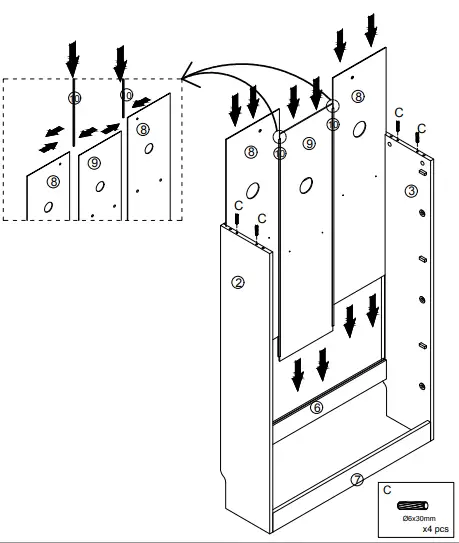
- Wood pins (C) are inserted in the upper parts of Plate 2 and Plate 3; Insert number 8 and number 9 back plate into the back plate slot of number 2 left side plate and 3 right side plate,

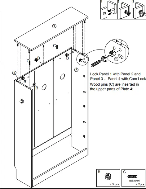
- Lock Panel 1 with Panel 2 and Panel 3 、Panel 4 with Cam Lock; B Wood pins (C) are inserted in 8 B the upper parts of Plate 4;

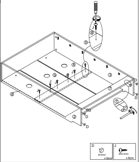
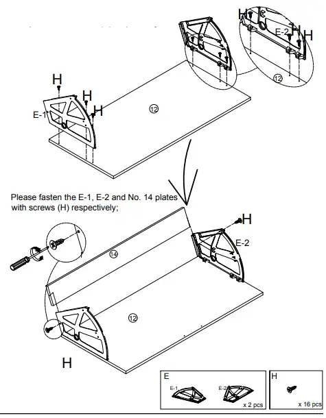
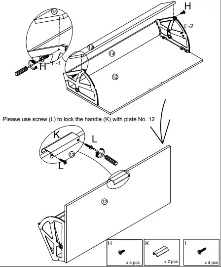
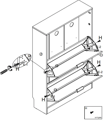
- Please use screw (J) to lock back plate No. 8, No. 9 and No. 5 respectively Please hammer the nail (D) under the No. 2, No. 3 and No. 7 boards x2 Please fasten the E-1, E-2 and No. 12 plates with screws (H) respectively.

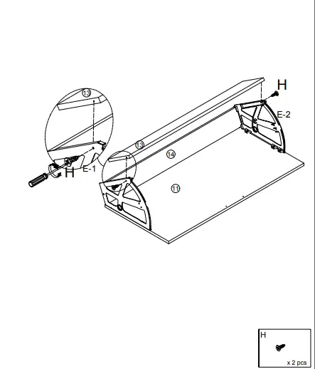
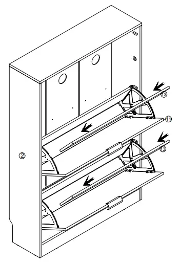
- x2 Please fasten the E-1, E-2 and No. 13 plates with screws (H) respectively;

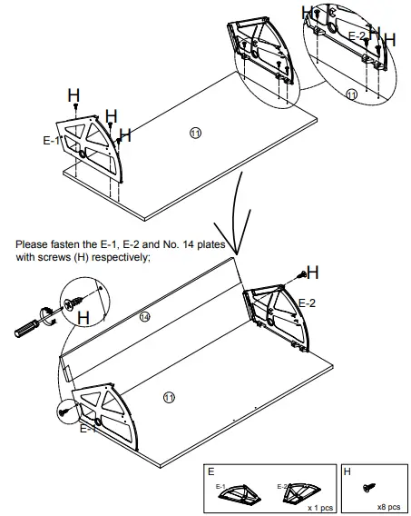
- Please fasten the E-1, E-2 and No. 11 plates with screws (H) respectively

- Please fasten the E-1, E-2 and No. 13 plates with screws (H) respectively;

- Please fasten the E-1, E-2 and No. 13 plates with screws (H) respectively;

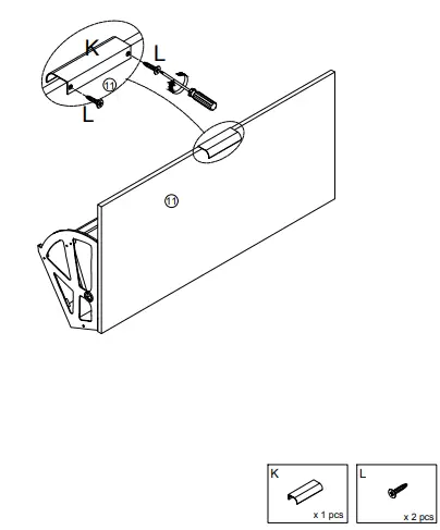
- Please use screw (L) to lock the handle (K) with plate No. 11

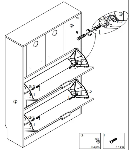
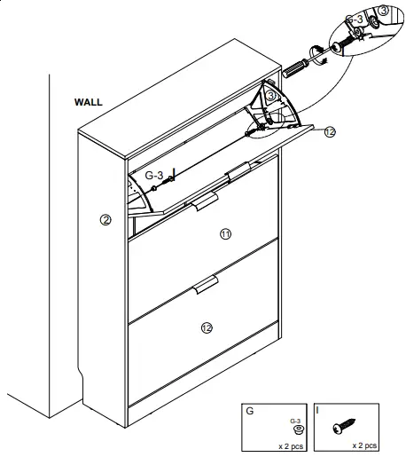
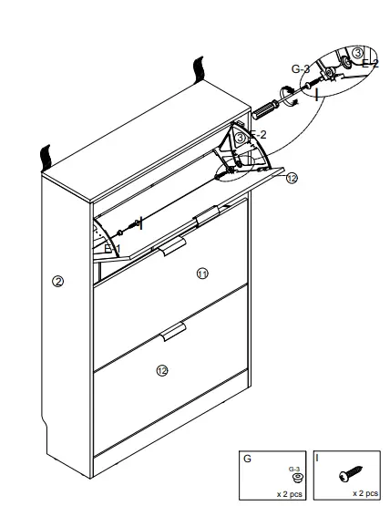
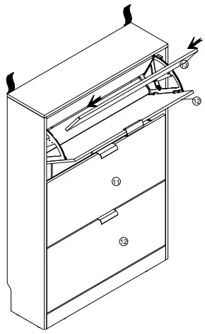
- Please use screw (I) to lock (G-3) through plate E-1 and No. 2 and plate E-2 and No. 2 respectively

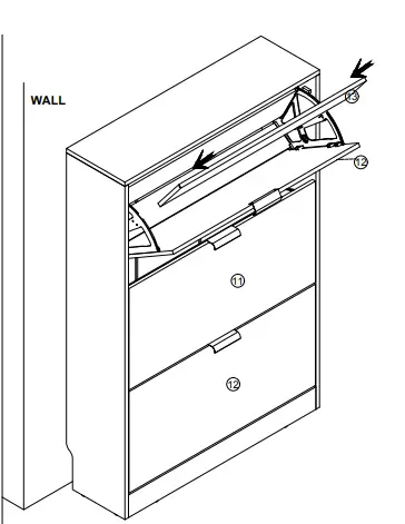
- Please insert panel 13 into the cabinet

- Please use screw H to lock the E-1 and E-2 with plate 13 respectively;

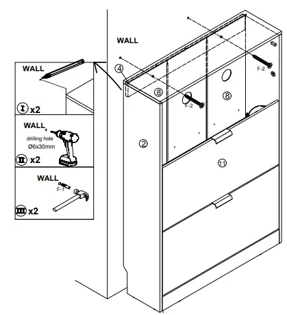
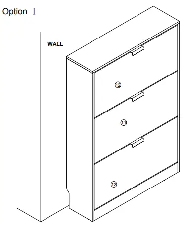
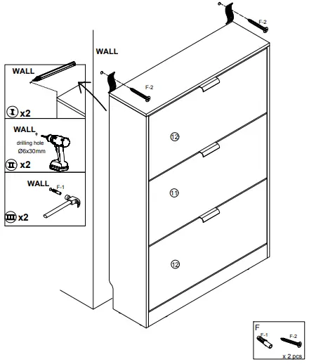
- Please users according to the actual needs, to choose a Option Ⅰ or Option Ⅱ Anti-pour, choose one of the options to install.
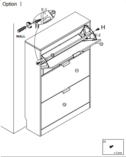
Option Ⅰ:
Please use a pen to locate the pour-proof position on the wall, guide the hole position with an impact rotation, then use a F-2 hammer to knock (F-1) against the wall, and use screws (F-2) to pass through plate 4 and Plate 8 to lock with the wall!
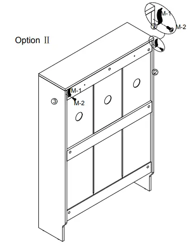
Option Ⅱ:
Please use the screw (M-2) to pass through the cloth M strip (M-1) and lock it with Plate 2 and Plate 3 respectively;
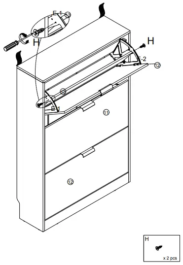
- Option Ⅰ Please use screw (I) to lock (G-3) through plate E-1 and No. 2 and plate E-2 and No. 2 respectively

Option Ⅱ Please use screw (I) to lock (G-3) through plate E-1 and No. 2 and plate E-2 and No. 2 respectively
- Option Ⅰ Please insert panel 13 into the cabinet

Option Ⅱ Please insert panel 13 into the cabinet
- Option Ⅰ Please use screw H to lock the E-1 and E-2 with plate 13 respectively; O

Option Ⅱ Please use screw H to lock the E-1 and E-2 with plate 13 respectively;
- Option Ⅰ

Option Ⅱ Please use the pen to locate the anti-toppling position on the wall, use the impact rotation guide hole position, then use the hammer to hit (F-1) the wall, use the screw (F-2) to pass through the cloth to lock with the wall!