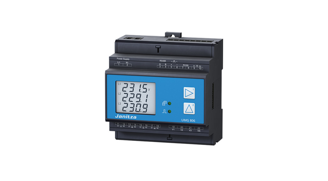
![]() UMG 806 Power Analyser
UMG 806 Power Analyser
User Manual
Doc no. 2.064.010.3.b 08/2022
Articel no.: 33.03.382
- Installation
- Device settings
General
Disclaimer
Observing the usage information for the devices is a prerequisite for safe operation and for achieving the specified performance characteristics and productfeatures. Janitza electronics GmbH assumes no liability for personal injuries, property damage and financiallosses resulting from the failure to observe the usageinformation. Make sure that your information productsare legible and accessible.
Further usage information, such as e.g. the user manual, can be found on our web site www.janitza.com under Support > Downloads.
Copyright notice
© 2019 – Janitza electronics GmbH – Lahnau.
All rights reserved. Any duplication, processing, distribution and any other kind of use, even in part, is prohibited.
Subject to technical changes.
- Make sure that the installation instructions match your device.
- Make sure you have first read and understood theusage information accompanying the product.
- Keep the usage information accompanying the product accessible through its service life and hand it over to the subsequent owner where applicable.
- Please refer to www.janitza.de for information concerning device revisions and the associated adjustments to the usage information accompanying the product.
Disposal
Please observe the national regulations. Dispose of individual parts, where necessary, depending on the properties and existing country-specific regulations, e.g. as:
- Electronic waste
- Batteries and accumulators
- Plastic
- Metals
or commission a certified disposal company with the scrapping.
Relevant laws, applied standards and directives
Please refer to the Declaration of Conformity on ourweb site (www.janitza.com) for the laws, standards anddirectives applied by Janitza electronics GmbH for the device.
Safety
Safety instructions
The installation instructions do not include a complete list of all safety measures necessary for operating the device.
Special operating conditions may require additional measures. The installation instructions contain notes that must be observed for your personal safety and to prevent property damage.
Symbols used on the device:
| The additional symbol on the device itself indicates an electrical danger that can result in serious injuries or death. | |
| The general warning symbol calls attention to possible risks of injury. Observe all the instructions listed under this symbol in order to prevent injuries or even death. |
Safety instructions in the installation instructions are highlighted with a warning triangle and are presented as follows depending on the level of risk:![]() DANGER
DANGER
Warns of an imminent danger that will result in serious or fatal injuries in the event of noncompliance.![]() WARNING
WARNING
Warns of a potentially dangerous situation that can result in serious injuries or death in the event of noncompliance.![]() CAUTION
CAUTION
Warns of an imminently dangerous situation that can result in minor or moderate injuries in the event of noncompliance.
ATTENTION
Warns of an imminently dangerous situation that can result in property damage or environmental damage in the event of noncompliance.![]() INFORMATION
INFORMATION
Points out procedures in which there are no dangers of personal injuries or property damage.
Safety measures
When operating electrical devices, specific parts of these devices inevitably carry dangerous voltage. As a result, serious personal injuries or property damage can occur if they are not handled correctly:
- Before connecting the device, ground it at the ground wire connection if available.
- Dangerous voltages may be present in all circuit parts connected to the voltage supply.
- There may still be dangerous voltages present in the device even after it is disconnected from the supply voltage (capacitor storage).
- Do not operate equipment with open current transformer circuits.
- Do not exceed the threshold values specified in the user manual and on the rating plate. This must also be observed during inspections and commissioning.
- Observe the safety instructions and warning noticesin the usage information that accompanies the devices and theircomponents!
![]() WARNING
WARNING
Danger due to noncompliance with warning andsafety instructions.
Noncompliance with warning and safety instructions on the device itself and in the information on using thedevice and its components can lead to injury or evendeath.
Observe safety instructions and warning notices on the device itself and in the usage information associated with the devices and their components, such as:
- Installation instructions.
- User manual.
- Safety instructions supplement.
Qualified personnel
To prevent personal injuries and property damage, only qualified personnel with electrical engineering training may work on the base unit and its components. They must also have knowledge
- of the national accident prevention regulations.
- of safety technology standards.
- in the installation, commissioning and operation of the device and the components.
![]() WARNING
WARNING
Risk of injury due to electric voltage or electrical current!
When handling electrical currents or voltages, serious personal injuries or death can occur due to:
- Touching live exposed or stripped cores.
- Device inputs that are dangerous to touch.
Before starting work on your system:
- Disconnect it from the power supply!
- Secure it against being switched back on!
- Verify disconnection from power!
- Ground and short circuit!
- Cover or block off neighboring parts that are under voltage!
Intended use
The device is
- intended for installation in switching cabinets and small installation distributors. The device can be installed in any mounting position (please observe section 3 “Assembly”).
- not intended for installation in vehicles! Using the device in mobile equipment is considered an unusual environmental condition and is only permissible by special agreement.
- not intended for installation in areas exposed to harmful oils, acids, gases, vapors, dust and radiation, etc.
- designed as an indoor meter.
Incoming goods inspection
The prerequisites for trouble-free and safe operation of the devices and their components include proper transport, storage, setup and assembly, as well as careful operation and maintenance.
Exercise caution when unpacking and packing the device, without using force and only using suitable tools.
Check:
- Devices and components by performing a visual inspection to ensure a flawless mechanical condition.
- The scope of delivery (see user manual) for completeness before beginning the installation of your devices and components.
If you assume that safe operation is no longer possible, shut down the device with components immediately and secure it from being unintentionally started back up again.
It can be assumed that safe operation is no longer possible, when, for example, the device with components:
- Has visible damage,
- No longer functions despite an intact power supply.
- Was subjected to extended periods of unfavorable conditions (e.g. storage outside of the permissible climate thresholds without adjustment to the room climate, condensation, etc.) or transport stress (e.g. falling from an elevated position, even without visible external damage, etc.).
Device short description and assembly
The device is a multifunctional power analyzer that
- measures and calculates electrical parameters, such as voltage, current, frequency, power, energy and harmonics, etc. in building installations, on distributors, circuit breakers and busbar trunking systems.
- displays and saves measurement results and transfers them via interfaces.
ATTENTION
Property damage due to noncompliance with the assembly instructions
Noncompliance with the assembly instructions can damage or destroy your device.
- Ensure sufficient air circulation in your installationenvironment and,where applicable, sufficient cooling with high ambient temperatures.
- You can find more detailed information about the device functions, data, assembly in the device in the user manual.
Mount the measurement device in switch cabinets or small distribution boards according to DIN 43880 (any installation position) on a 35 mm (1.38 in) DIN rail, as follows: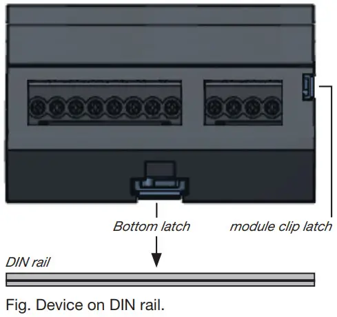
Connecting the supply voltage
The supply voltage level for your device can be found on the rating plate or in the technical data. After connecting the supply voltage, a display appears. If no display appears, check whether the supply voltage is within the rated voltage range.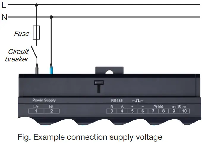
ATTENTION
Property damage due to noncompliance with the connection conditions or impermissible overvoltages
Noncompliance of the connection conditions or exceeding the permissible voltage range can damage or destroy your device.
Before you connect the device to the supply voltage, please observe the following:
- The voltage and frequency must comply with the specifications on the rating plate. Observe the limit values as described in the user manual.
- In building installations, secure the supply voltage with a UL/IEC-listed circuit breaker/fuse.
- The circuit breaker
– must be easily accessible for the user and located in the vicinity of the device.
– must be labeled for the respective device. - Do not tap the supply voltage at the voltage transformers.
- Provide a fuse for the neutral conductor if the neutral conductor connection is not grounded to the source.
Network systems
Suitable network systems and maximum rated voltages (DIN EN 61010-1/A1):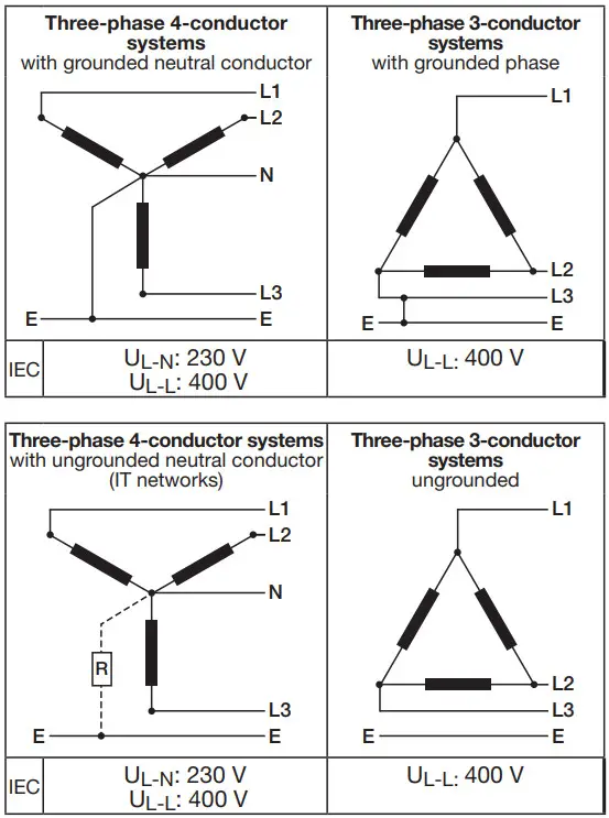
Application areas of the device:
- 3 and 4 conductor networks (TN, TT and IT networks).
- Residential and industrial sectors.
Voltage/Current measurement
The device
- has 4 voltage inputs
- measures current exclusively via a current transformer.
- permits connection of current transformers with a transformer ratio of ../1 A and ../5 A
- does not measure DC currents.
The current transformers require basic insulation according to IEC 61010-1:2010 for the rated voltage of the circuit.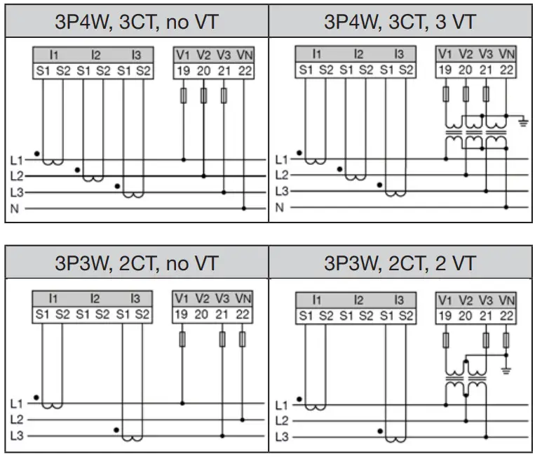
![]() WARNING
WARNING
Risk of injury or damage to the device due to electrical voltage and improper connection!
Disregard of the conditions for the connections of the voltage and current measurement inputs may damage the device or cause serious injury or death. Connecting the voltage lines to the current measurement inputs also poses a fire hazard!
Therefore please abide by the following:
- Switch off your installation before commencing work! Secure it against being switched on! Check to be sure it is de-energized! Ground and short circuit! Cover or block off adjacent live parts!
- Check the condition of the connections, including the cabling, especially the connection of the voltage and current measurement.
- Do not apply a DC voltage
– to the voltage measurement inputs.
– Equip the voltage measurement inputs with a suitable, marked fuse and isolation device (alternatively: line circuit breaker) located nearby.
– The voltage measurement inputs are dangerous to touch. - Connect voltages that exceed the permissible nominal network voltages via a voltage transformer.
- Measured voltages and currents must originate from the same network.
![]() WARNING
WARNING
Risk of injury due to high currents and high electrical voltages!
Serious personal injuries or death can occur due to:
- Touching live exposed or stripped cores.
- Device inputs that are dangerous to touch.
Therefore, please observe the following for your system:
- Before starting work, disconnect it from the power supply!
- Secure it against being switched back on!
- Verify disconnection from power!
- Ground and short circuit! Use the ground connection points with the ground symbol for grounding!
- Cover or block off neighboring parts that are under voltage!
![]() WARNING
WARNING
Electrical currents and voltages!
Open current transformers that are operated on the
secondary side (high voltage spikes) can result in serious personal injuries or even death.
Avoid the open operation of the current transformers and short-circuit unloaded transformers.
Establishing the connection to the PC
The most common connections for the communication between the PC and device: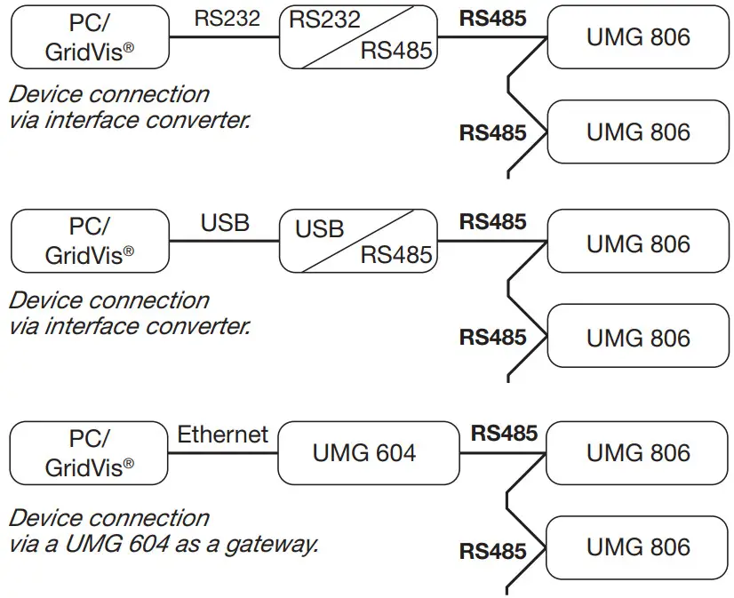
![]() CAUTION
CAUTION
Property damage due to incorrect network settings.
Incorrect network settings can cause faults in the IT network!
Consult your network administrator for the correct network settings for your device.
Example: PC connection via RS485 interface and UMG 604 as the gateway
The PC connection to the device via the RS485 serial interface with, e.g. a UMG 604 as the gateway (see section “Establishing the connection to the PC”) is a method for configuring the device(s)/and reading out data.
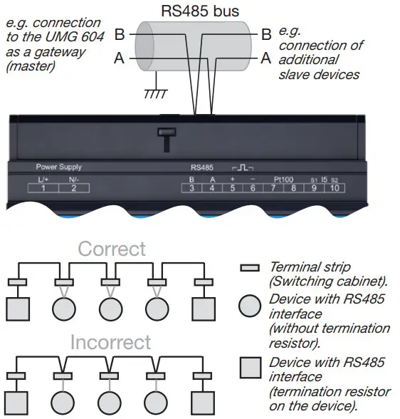
RS485 bus structure
- Connect all devices in the RS485 bus structure (line) according to the master/slave principle.
- A segment of a RS485 bus structure can contain up to32 participants/devices.
- Terminate the cable with termination resistors (120 Ω, 0.25 W) at the beginning and end of a segment. The device does not contain a termination resistor.
- With more that 32 participants, use repeaters to connect segments.
- Further information, e.g. Cable type, refer to the user manual.

ATTENTION
Using the corresponding menu items, assign the slave devices in the RS485 bus structure
- Different device addresses.
- Different device addresses compared to the master device (UMG 604).
- The same transmission rate (baud rate).
- The same data frame.
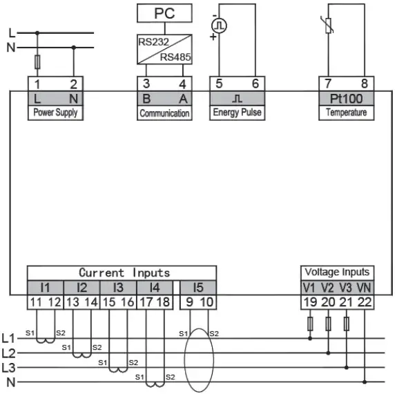
Wiring of UMG 806
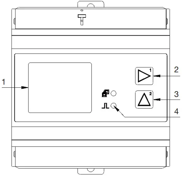
Operation
 Display
- Button 1
- Button 2
- Indicator lights
 Display
Configure device:
- Press and hold buttons 1 and 2 simultaneously for 1 s to switch between display and configuration mode.
- Enter the password with button 1 (confirm / change digit position) and 2 (increase digit) in the display (factory setting: 0000 – no password).
- The 1st parameter address 000 appears for the configuration of the primary current transformers I1-I3. Configure with buttons 1 and 2, if necessary, additional parameters (see table „Basic parameters“).
A parameter list for further configuration can also be found in the user manual (www.janitza.de). - To complete and save your configuration, press buttons 1 and 2 simultaneously.
- The device switches to display mode.
![]() INFORMATION
INFORMATION
- A detailed description of the configuration of the device and the parameters can be found in the user manual.
- Other usage information, such as the user manual or a Modbus address list can be found on our homepage www.janitza.de under Support> Download.
Basic parameters
| Adress | Description |
| 000 | Current transformer, primary, I1..I3 |
| 001 | Current transformer, secondary, I1..I3 |
| 002 | Voltage transformer, primary, V1..V3 (L1..L3). |
| 003 | Voltage transformer, secondary, V1..V3 (L1..L3) |
| 010 | Current transformer, primary, I4 |
| 011 | Current transformer, secondary, I4 |
| 020 | Residual current transformer, primary, I5 |
| 021 | Residual current transformer, secondary, I5 |
| 110 | Network system / wiring 0: 3P4W (default setting) 1: 3P3W 2: 1P2W |
| 200 | Device address (1 .. 247) |
| 201 | Baud rate, RS485 0 = 9600 bit/s 1 = 19200 bit/s 2 = 38400 bit/s 3 = 57600 bit/s 4 = 115200 bit/s |
| 202 | RS485, parity 0 = N.8.1 1 = E.8.1 2 = O.8.1 3 = N.8.2 |
| 203 | RS485, mode 0 = Modbus RTU/slave 1 = gateway |
Technical data
| General information | |
| Net weight | 300 g (0.66 lb) |
| Device dimensions | approx. w = 90 mm (3.54 in), h = 90 mm (3.54 in), d = 63.5 mm (2.50 in) |
| Battery | Type CR2032, 3 V, Li-Mn |
| Service life of the backlight | 45000 h (50 % of the starting brightness) |
| Installation position | discretionary |
| Impact resistance | IK04 according to IEC 62262 |
| Transport and storage The following information applies to devices which are transported and stored in the original packaging. | |
| Free fall | 1 m (39.37 in) |
| Temperature | -30 °C (-22 °F) up to +80 °C (176 °F) |
| Relative humidity | 5 to 95 % at 25 °C (77 °F) without condensation |
| Ambient conditions during operation | |
| The device • must be used in a weather-protected, stationary application. • fulfills the operating conditions according to DIN IEC 60721-3-3. • possesses protection class II according to IEC 60536 (VDE 0106, Part 1), a ground wire connection is not required! | |
| Measurement tempera- ture range | -25 °C (-13 °F) .. +70 °C (158 °F) |
| Relative humidity | 5 to 95 % at 25 °C (77 °F) without condensation |
| Operating height | < 2500 m (1.55 mi) above sea level |
| Pollution degree | 2 |
| Ventilation | No external ventilation required. |
| Protection against foreign bodies and water | IP20 i.a.w. EN60529 |
| Supply voltage | |
| Nominal range | AC/DC: 80 V – 270 V |
| Operating range | +/-10% of the nominal range |
| Power consumption | max. 7 VA |
| Recommended overcurrent protection device for the line protection | 5 A (char. B), IEC-/UL approval |
| Voltage measurement | |
| 3-phase 4-conductor systems with rated voltages up to | 230 VLN / 400 VLL (+/-10%) acc. IEC |
| 3-phase 3-conductor systems with rated voltages up to | 400 VL-L (+/-10%) acc. IEC |
| Overvoltage category | 300 V CAT III acc. IEC |
| Rated surge voltage | 4 kV |
| Fuse for the voltage measurement | 1 – 10 A tripping characteristic B (with IEC/UL approval) |
| Metering range L-N | 0 .. 230 Vrms (max. overvoltage 277 Vrms ) |
| Metering range L-L | 0 .. 400 Vrms (max. overvoltage 480 Vrms ) |
| Resolution | 0.1 V |
| Crest factor | 2 (based on the metering range 230 V L-N) |
| Impedance | ≥ 1.7 MΩ/phase |
| Power consumption | approx. 0.1 VA / phase |
| Sampling frequency | 8 kHz / phase |
| Frequency of the basic oscillation – resolution | 45 Hz .. 65 Hz 0.01 Hz |
| Harmonics | 1 .. 31. |
| Current measurement (../1A) (../5A) | |
| Rated current | 5 A |
| Channels | 4 |
| Metering range | 0.005 .. 6 Arms |
| Crest factor (based on the rated current) | 2 |
| Overload for 1 sec. | 100 A (sinusoidal) |
| Resolution | 1 mA |
| Overvoltage category | 300 V CATII |
| Rated surge voltage | 4 kV |
| Power consumption | approx. 0.2 VA |
| Sampling frequency | 8 kHz |
| Harmonics | 1 .. 31. |
| Current measurement (0 .. 40 mA, AC) | |
| Channel (I5) | 1 |
| Digital output Energy pulse output | |
| Switching voltage | max. 35 V DC |
| Switching current | max. 10 mAeff DC |
| Response time | approx. 500 ms |
| Pulse width | 80 ms ±20 % |
| Pulse output (energy pulse) | max. 10 Hz |
| Temperature measurement | |
| Update time | 1 s |
| Total burden (sensor and lead) | max. 0.35 k Ω |
| Suitable sensor types | PT100 |
| Line length (digital output; temp. measurement) | |
| Up to 30 m (32.81 yd.) | Unshielded |
| Greater than 30 m (32.81 yd.) | Shielded |
| RS485 interface 2-wire connection. | |
| Protocol | Modbus RTU |
| Transmission rate | up to 115.2 kbps |
| Terminal connection capacity (supply voltage) Connectable conductors. Only one conductor can be connected per terminal. | |
| Single core, multi-core, fine-stranded | 0.14 – 2.5 mm2, AWG 26-14 |
| Cable end sleeve (not insulated) | 0.25 – 2.5 mm2, AWG 23-14 |
| Cable end sleeve (insulated) | 0.25 – 1.5 mm2, AWG 23-16 |
| Tightening torque | 0.5 – 0.6 Nm (4.4 – 5.3 lbf in) |
| Stripping length | 7 mm (0.2756 in) |
| Terminal connection capacity (current measurement) Connectable conductors. Only one conductor can be connected per terminal. | |
| Single core, multi-core, fine-stranded | 0.2 – 4 mm2, AWG 24-12 |
| Cable end sleeve (not insulated) | 0.25- 2.5 mm2, AWG 23-14 |
| Cable end sleeve (insulated) | 0.25 – 1.5 mm2, AWG 23-16 |
| Tightening torque | 0.5 – 0.6 Nm (4.4 – 5.3 lbf in) |
| Stripping length | 7 mm (0.2756 in) |
| Terminal connection capacity (voltage measurement) Connectable conductors. Only one conductor can be connected per terminal. | |
| Single core, multi-core, fine-stranded | 0.2 – 4 mm2, AWG 24-12 |
| Cable end sleeve (insulated/not insulated) | 0.25- 2.5 mm2, AWG 23-14 |
| Stripping length | 7 mm (0.2756 in) |
| Terminal connection capacity (RS485, digital output, temp. measurement) | |
| Single core, multi-core, fine-stranded | 0.2 – 4 mm2, AWG 24-12 |
| Cable end sleeve (not insulated) | 0.25- 2.5 mm2, AWG 23-14 |
| Cable end sleeve (insulated) | 0.25 – 1.5 mm2, AWG 23-16 |
| Tightening torque | 0.5 – 0.6 Nm (4.4 – 5.3 lbf in) |
| Stripping length | 7 mm (0.2756 in) |
![]() INFORMATION
INFORMATION
Additional technical data can be found in the user manual for the device at www.janitza.com
![]() Janitza electronics GmbH
Janitza electronics GmbH
Vor dem Polstück 6
35633 Lahnau
Germany
Support Tel. +49 6441 9642-22
[email protected]
www.janitza.com


