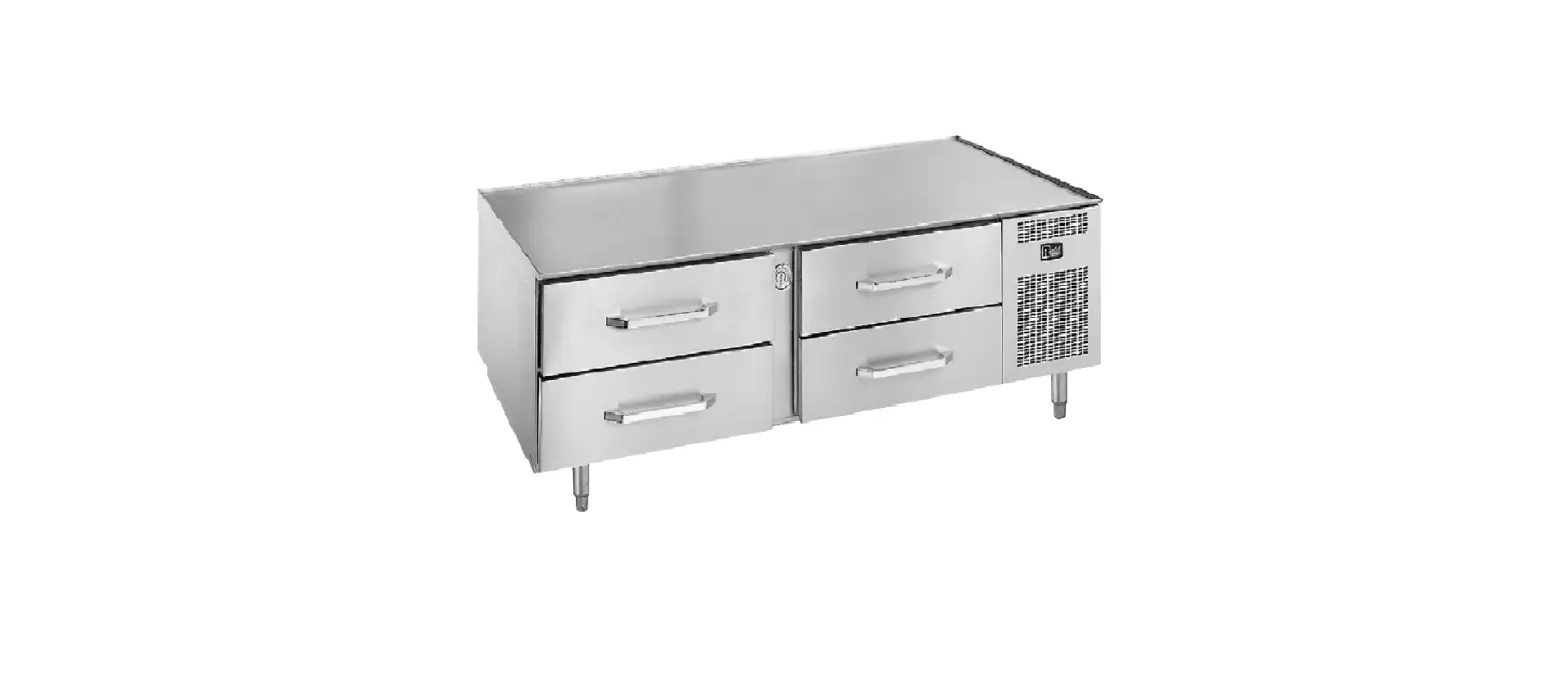
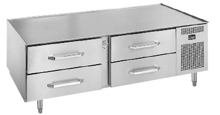
randell PP MNL1712 20000 Series Self-Contained Low Profile Equipment Tables
RETAIN THIS MANUAL FOR FUTURE REFERENCE
NOTICE: Due to a continuous program of product improvement, Unified Brands reserves the right to make changes in design and specifications without prior notice. Please read the entire manual carefully before installation. If certain recommended procedures are not followed, warranty claims will be denied.
MODEL NUMBER:
SERIAL NUMBER:
INSTALLATION DATE: 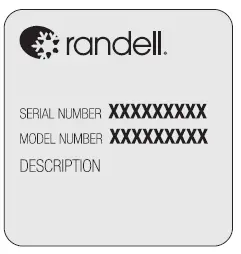 The serial number is located in the mechanical housing. An example is shown here.
THIS MANUAL MUST BE RETAINED FOR FUTURE REFERENCE. READ, UNDERSTAND AND FOLLOW THE INSTRUCTIONS AND WARNINGS CONTAINED IN THIS MANUAL.
FOR YOUR SAFETY: Do not store or use gasoline or other flammable vapors and liquids in the vicinity of this or any other appliance.
WARNING: Improper installation, adjustment, alteration, service or maintenance can cause property damage, injury or death. Read the installation, operating and maintenance instructions thoroughly before installing or servicing this equipment.
NOTIFY CARRIER OF DAMAGE AT ONCE: It is the responsibility of the consignee to inspect the container upon receipt of same and to determine the possibility of any damage, including concealed damage. Unified Brands suggests that if you are suspicious of damage to make a notation on the delivery receipt. It will be the responsibility of the consignee to file a claim with the carrier. We recommend that you do so at once.
Manufacture Service/Questions 888-994-7636.
EQUIPMENT DESCRIPTION
| MODEL | LENGTH | DEPTH | HEIGHT | DRAWERS | 12x20x4 PAN CAPACITY | HP | VOLT | AMPS | NEMA | SHIP WT (LBS) |
| 20048-513 | 48″ | 32.5″ | 26″ | (2) 27″ | 4 | 1/4 | 115 | 6 | 5-15P | 400 |
| 20048-32-513 | 53″ | 32.5″ | 26″ | (2) 32″ | 4 | 1/4 | 115 | 6 | 5-15P | 400 |
| 20072-513 | 72″ | 32.5″ | 26″ | (4) 27″ | 8 | 1/3 | 115 | 7.4 | 5-15P | 530 |
| 20072-32-513 | 82″ | 32.5″ | 26″ | (2) 32″ | 8 | 1/3 | 115 | 7.4 | 5-15P | 530 |
| 20078-513 | 78″ | 32.5″ | 26″ | (4) 27″ | 8 | 1/3 | 115 | 7.4 | 5-15P | 530 |
| 20105-513 | 105″ | 32.5″ | 26″ | (6) 27″ | 12 | 1/2 | 115 | 12 | 5-15P | 675 |
| 20105-32-513 | 120″ | 32.5″ | 26″ | (6) 32″ | 12 | 1/2 | 115 | 12 | 5-15P | 950 |
INSTALLATION
SELECTING A LOCATION FOR YOUR NEW UNIT
The following conditions should be considered when selecting a location for your unit:
- Floor Load: The area on which the unit will rest must be level, free of vibration, and suitably strong enough to support the combined weights of the unit plus the maximum product load weight. All casters or legs must in contact with the floor. Adjust legs or add shims to casters for uneven floor surfaces. NOTE: Randell’s Low Profile Equipment Stands are designed to support the weight of standard cooking equipment, such as griddles, fryers, and cook top ranges. For non-standard cooking equipment or if there is a question pertaining to weight load limits, consult the factory at 1-888-994-7636.
- Clearance: There must be a combined total of at least 3” clearance on all sides of the unit. A minimum of 4” clearance is required between cooking appliance and equipment stand.
- Ventilation: The air cooled self contained unit requires a sufficient amount of cool clean air. Avoid surrounding your equipment stand around other heat generating equipment and out of direct sunlight. Also, avoid locating in an unheated room or where the room temperature may drop below 70°F (21°C) or above 86°F (32°C).
INSTALLATION CHECKLIST
WARNING: FAILURE TO FOLLOW INSTALLATION GUIDELINES AND RECOMMENDATIONS MAY VOID THE WARRANTY ON YOUR UNIT.
After the final location has been determined, refer to the following checklist prior to start-up:
- Check all exposed refrigeration lines to ensure that they are not kinked, dented, or rubbing together.
- Check that the condenser and evaporator fans rotate freely without striking any stationary members.
- Unit must be properly leveled; check all legs or casters to ensure they all are in contact with the floor while maintaining a level work surface. Adjusting bullet feet heights or shimming casters may be necessary if the floor is not level. NOTE: Damage to equipment may result if not followed. Unified Brands is not responsible for damage to equipment if improperly installed.
- Plug in unit and turn on main on/off power switch.
- Allow unit time to cool down to temperature. If temperature adjustments are required, the temperature control is located within the cabinet on the front face of the evaporator coil behind the thermometer (Note: The left set of drawers or center set for a 6 drawer unit must be removed to access the temperature adjustment control).
- Refer to the front of this manual for serial number location. Please record this information in your manual on page 3 now. It will be necessary when ordering replacement parts or requesting warranty service.
- Confirm that the unit is holding temperature. Set controls to desired temperature for your particular ambient and altitude.
- Allow your unit to operate for approximately 2 hours before putting in food to allow interior of unit to cool down to storage temperature. NOTE: All motors are oiled and sealed.
ELECTRICAL SUPPLY
WARNING
IT IS IMPORTANT THAT A VOLTAGE READING BE MADE AT THE COMPRESSOR MOTOR ELECTRICAL CONNECTIONS, WHILE THE UNIT IS IN OPERATION TO VERIFY THE CORRECT VOLTAGE REQUIRED BY THE COMPRESSOR IS BEING SUPPLIED. LOW OR HIGH VOLTAGE CAN DETRIMENTALLY AFFECT OPERATION AND THEREBY VOID ITS WARRANTY.
IT IS IMPORTANT THAT YOUR UNIT HAS ITS OWN DEDICATED LINE. CONDENSING UNITS ARE DESIGNED TO OPERATE WITH A VOLTAGE FLUCTUATION OF PLUS OR MINUS 10% OF THE VOLTAGE INDICATED ON THE UNIT DATA TAG. BURN OUT OF A CONDENSING UNIT DUE TO EXCEEDING VOLTAGE LIMITS WILL VOID THE WARRANTY.
The wiring should be done by a qualified electrician in accordance with local electrical codes. A properly wired and grounded outlet will assure proper operation. Please consult the data tag attached to the compressor to ascertain the correct electrical requirements. Supply voltage and amperage requirements are located on the serial number tag located inside the mechanical housing.
OPERATION
MECHANICAL COMPARTMENT
WARNING: EVEN THOUGH YOUR EQUIPMENT STAND WAS DESIGNED FOR HEAVY USE, EXCESSIVE DRAWER OPENINGS SHOULD BE AVOIDED IN ORDER TO MAINTAIN PROPER CABINET TEMPERATURE AND ELIMINATE THE POSSIBILITY OF COIL FREEZE-UP.
Randell has attempted to preset the cold controls to ensure that your unit runs at an optimum temperature, but due to varying ambient conditions, including elevation, food product as well as type of operation, you may need to alter this temperature.
It is strongly recommended that the drawers be kept closed when the unit is not in use and between rush periods. This is especially important in the summer and in kitchens exceeding 86°F. Do not leave the drawers open for prolonged periods of time.
TEMPERATURE CONTROL
Your equipment stand was equipped with a temperature adjustment control located within the cabinet on the front face of the evaporator coil behind the thermometer (Note: The left set of drawers or center set for a 6 drawer unit must be removed to access the temperature adjustment control).
To adjust the temperature in refrigerated units:
- To lower the temperature:
- Turn the dial knob clockwise.
- There are numbers to indicate settings. Keep the arrow on the knob pointed within the numbered section of the arc.
- Turning it clockwise beyond the numbered section can result in freeze-up.
- To raise the temperature:
- Turn the dial knob counterclockwise.
- There are numbers to indicate settings. Keep the arrow on the knob pointed within the numbered section of the arc.
- Turning it counterclockwise beyond the numbered section will shut the compressor off.
NOTE: It is not recommended to turn the dial above 8 or below 1 on the temperature control. If the adjustments still do not result in proper temperature please contact the factory at 1-888-994-7636.
- If your temperature control is at the maximum setting and the cabinet temperature still remains too low or too high, you may need to adjust the pressure control.
- Turn the right adjustment screw clockwise (1/4 turn at a time) to a lower number for a colder temperature.
- Turn the right adjustment screw counterclockwise (1/4 turn at a time) to a higher number for a warmer temperature.
NOTE: Numbers on pressure control are pounds of pressure, not degrees F. NOTE: Do not adjust the differential screw.
DRAWER REMOVAL
- Fully extend the drawer that is to be removed.
- Remove product pans from drawer.
- Lift up the drawer stop tabs on each side of drawer track.
- Pull drawer out while lifting the tabs.
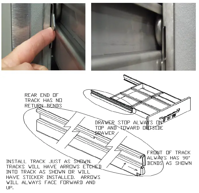
DRAWER INSTALLATION
To remove and re-install individual drawers and drawer tracks, please refer to the figure above for proper installation instructions.
DRAWER CARTRIDGE SYSTEM REMOVAL
Drawer cartridge system has a single plate in rear to hold in place. To remove the entire drawer system, unscrew the thumb screws on rear wall to detach system from the plate. See figures below.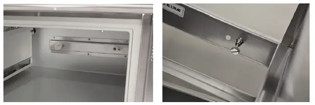
MAINTENANCE
WARNING
- DO NOT USE SHARP UTENSILS AND/OR OBJECTS.
- DO NOT USE STEEL PADS, WIRE BRUSHES, SCRAPERS, OR CHLORIDE CLEANERS TO CLEAN YOUR STAINLESS STEEL.
CAUTION: DO NOT USE ABRASIVE CLEANING SOLVENTS, AND NEVER USE HYDROCHLORIC ACID (MURIATIC ACID) ON STAINLESS STEEL.
WARNING: DO NOT PRESSURE WASH EQUIPMENT AS DAMAGE TO ELECTRICAL COMPONENTS MAY RESULT.
Unified Brands strongly suggests a preventive maintenance program which would include the following monthly procedures:
If a failure of the equipment is a direct result of any of the Preventative Maintenance guidelines being neglected, the repairs and parts replacements will not be covered under warranty.
It is recommended that the customer contact the local Authorized Service Agent to provide a quote to perform periodic Preventative Maintenance.
MONTHLY PM PROCEDURES
- Cleaning of all condenser coils. Condenser coils are a critical component in the life of the compressor and must remain clean to assure proper air flow and heat transfer. Failure to maintain this heat transfer will affect unit performance and eventually destroy the compressor. Clean the condenser coils with coil cleaner and/or a vacuum, cleaner and brush. NOTE: Brush coil in direction of fins, normally vertically as to not damage or restrict air from passing through condenser.
- Clean fan blade on the condensing unit.
- Clean and disinfect drains with a solution of warm water and mild detergent
- Clean and disinfect drain lines and evaporator pan with a solution of warm water and mild detergent
- Clean all gaskets on a weekly if not daily basis with a solution of warm water and a mild detergent to extend gasket life.
- Remove debris from drawer slides.
RECOMMENDED CLEANERS FOR YOUR STAINLESS STEEL INCLUDE THE FOLLOWING:
| JOB | CLEANING AGENT | COMMENTS |
| Routine cleaning | Soap, ammonia, detergent Medallion | Apply with a sponge or cloth |
| Fingerprints and smears | Arcal 20, Lac-O-Nu, Ecoshine | Provides a barrier film |
| Stubborn stains and discoloration | Cameo, Talc, Zud, First Impression | Rub in the direction of the polish lines |
| Greasy and fatty acids, blood, burnt-on foods | Easy-Off, Degrease It, Oven Aid | Excellent removal on all finishes |
| Grease and Oil | Any good commercial detergent | Apply with a sponge or cloth |
| Restoration/Preservation | Benefit, Super Sheen | Good idea monthly |
Reference: Nickel Development Institute, Diversey Lever, Savin, Ecolab, NAFEM
Proper maintenance of equipment is the ultimate necessity in preventing costly repairs. By evaluating each unit on a regular schedule, you can often catch and repair minor problems before they completely disable the unit and become burdensome on your entire operation.
For more information on preventive maintenance, consult your local service company or CFESA member. Most repair companies offer this service at very reasonable rates to allow you the time you need to run your business along with the peace of mind that all your equipment will last throughout its expected life. These services often offer guarantees as well as the flexibility in scheduling or maintenance for your convenience. For a complete listing of current Unified Brands ASA please visit www.unifiedbrands.net.
Unified Brands believes strongly in the products it manufactures and backs those products with one of the best warranties in the industry. We believe with the proper maintenance and use, you will realize a profitable return on your investment and years of satisfied service.
REPLACEMENT PARTS
To order parts, contact your Authorized Service Agent. Supply the model designation, serial number, part description, part number, quantity, and when applicable, voltage and phase.
CONTACT US
If you have questions pertaining to the content in this manual, contact Unified Brands at 888-994-7636.
TROUBLESHOOTING
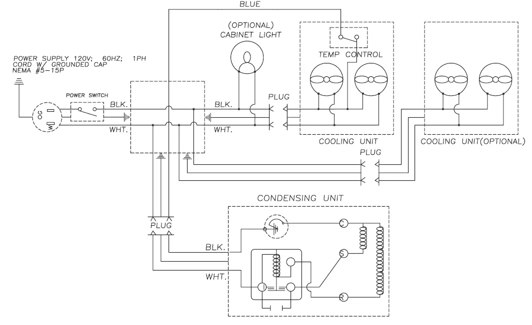
This unit is designed to operate smoothly and efficiently if properly maintained. However, the following is a list of checks to make in the event of a problem. Wiring diagrams are found at the end of this manual. When in doubt, turn unit off and call for service at 888-994-7636.
| SYMPTOM | POSSIBLE CAUSE | PROCEDURE |
|
Unit does not run | 1. No power to unit 2. Power switch in OFF position 3. Temperature control turned off 4. Temperature control faulty 5. Compressor overheated 6. Condenser fan faulty 7. Overload protector faulty 8. Compressor relay faulty 9. Compressor faulty | 1. Plug in unit 2. Switch power switch to ON 3. Check temperature control 4. Test temperature control 5. Clean condenser coil 6. Service condenser fan 7. Test overload 8. Test relay 9. Call for service at 888- 994-7636 |
|
Unit short cycles | 1. Condenser coil dirty 2. Condenser fan faulty 3. Compressor faulty 4. Overload repeatedly tripping | 1. Clean coil 2. Service fan and motor 3. Call for service at 888- 994-7636 4. Check outlet voltage |
|
Unit runs constantly | 1. Condenser coil dirty 2. Condenser fan faulty 3. Room ambient too high 4. Room humidity too high 5. Frost build up 6. Door gasket damaged 7. Poor door seal | 1. Clean coil 2. Service condenser motor 3. Reduce room temperature 4. Set room lower 5. Defrost evaporator 6. Replace door gasket 7. Check door seal |
|
Unit not cold enough | 1. Temperature control set too high 2. Temperature control faulty 3. Condenser coil dirty 4. Refrigerant leaking or contaminated 5. Room ambient too high 6. Room humidity too high 7. Door gasket damaged 8. Poor door seal 9. Evaporator fan faulty 10. Evaporator iced up | 1. Adjust control to lower setting 2. Test control 3. Clean coil 4. Call for service at 888- 994-7636 5. Reduce room temperature 6. Set room lower 7. Replace door gasket 8. Check door seal 9. Service evaporator fan 10. Defrost evaporator, Test defrost timer, Test Therm- O-Disc, Test defrost timer |
| Unit too cold | 1. Temperature control set too low 2. Temperature control faulty | 1. Adjust control to raise setting 2. Test control |
|
Unit noisy | 1. Compressor mountings loose or hardened 2. Condenser fan damaged or hitting fan shroud 3. Unit not level 4. Evaporator fan damaged or hitting fan shroud | 1. Tighten or replace compressor mountings 2. Inspect condenser fan 3. Adjust leveling feet 4. Inspect evaporator fan |
| Unit does not defrost | 1. Defrost heater faulty 2. Defrost Therm-O-Disc faulty 3. Defrost timer faulty | 1. Test heater 2. Test Therm-O-Disc 3. Test timer |
| Moisture around door or frame | 1. Breaker strip faulty 2. Frame heater faulty 3. Temperature control set too low | 1. Inspect strips 2. Call for service at 888- 994-7636 3. Adjust control to raise setting |
| Ice in drain pain or water in bottom of unit or floor | 1. Drain tube clogged 2. Unit not level | 1. Clean drain 2. Adjust leveling feet |
Parts List
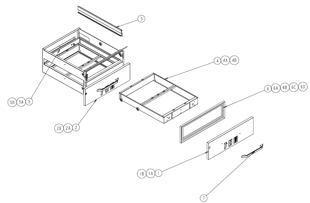
| ITEM | SERVICE PART | DESCRIPTION |
| 1 | RP FRT05T | Drawer Front, 27”, Top |
| 1A | RP FRT118 | Drawer Front, 19”, Top |
| 1B | RP FRT35T | Drawer Front, 32”, Top |
| 2 | RP FRT05B | Drawer Front, 27”, Bottom |
| 2A | RP FRT119 | Drawer Front, 19”, Bottom |
| 2B | RP FRT35B | Drawer Front, 32”, Bottom |
| 3 | RP TRK05SM | Drawer Track, 2pc. Set (Jan 1997-present) |
| 4 | RP FRM127E | Drawer Frame, 27” Extendable |
| 4A | RP FRM019 | Drawer Frame, 19” Non-extendable |
| 4B | RP FRM132E | Drawer Frame, 32” Extendable |
| 5 | RP MPT027 | Mounting Plate for 27” Drawer |
| 5A | RP MPT019 | Mounting Plate for 19” Drawer |
| 5B | RP MPT032 | Mounting Plate for 32” Drawer |
| 6 | IN GSK1070 | Drawer Gasket, 27” DR. FR. 24.75 X 7.25 PRESS IN |
| 6A | IN GSK1081 | Drawer Gasket, 19” DR. FT. 16.75 X 7.25 PRESS IN |
| 6B | IN GSK1075 | Drawer Gasket, 32” DR. FT. 29.75 X 7.25 PRESS IN |
| 6C | IN GSK195 | Drawer Gasket, 27” DR. FT. 24.75 X 7.25 SCREW IN |
| 6D | IN GSK196 | Drawer Gasket, 32” DR. FT. 29.75 X 7.25 SCREW IN |
| 7 | HD HDL130 | Sculptured Handle, 12-13/16” |
| 8 | HD THR9901 | Dial Thermometer |
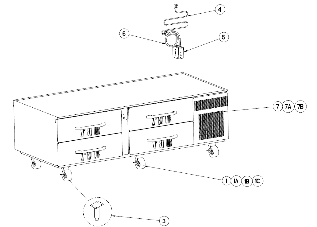
| ITEM | SERVICE PART | DESCRIPTION |
| 1 | HD CST030 | 4 ½” Heavy Duty Casters w/locking mechanism |
| 1A | HD CST031 | 4 ½” Heavy Duty Casters w/out locking mechanism |
| 1B | HD CST0213 | 5 ½” Heavy Duty Casters w/locking mechanism |
| 1C | HD CST0212 | 5 ½” Heavy Duty Casters w/out locking mechanism |
| 2 | RP KIT0412 | Caster Shim Plate (20pc) |
| 3 | HD LEG9902 | 6” Stainless Steel Legs w/adjustable bullet feet |
| 4 | EL WIR461 | Power Cord, Male 9’ |
| 5 | EL SWT0502 | Rocker On/Off Switch |
| 6 | EL WIR469 | Power Cord, Female 12” |
| 7 | RP LVR0321 | Mechanical Housing Louver, 20048SC & 20072SC only |
| 7A | RP LVR0505 | Mechanical Housing Louver, 20078SC only |
| 7B | RP LVR0322 | Mechanical Housing Louver, 20105SC only |
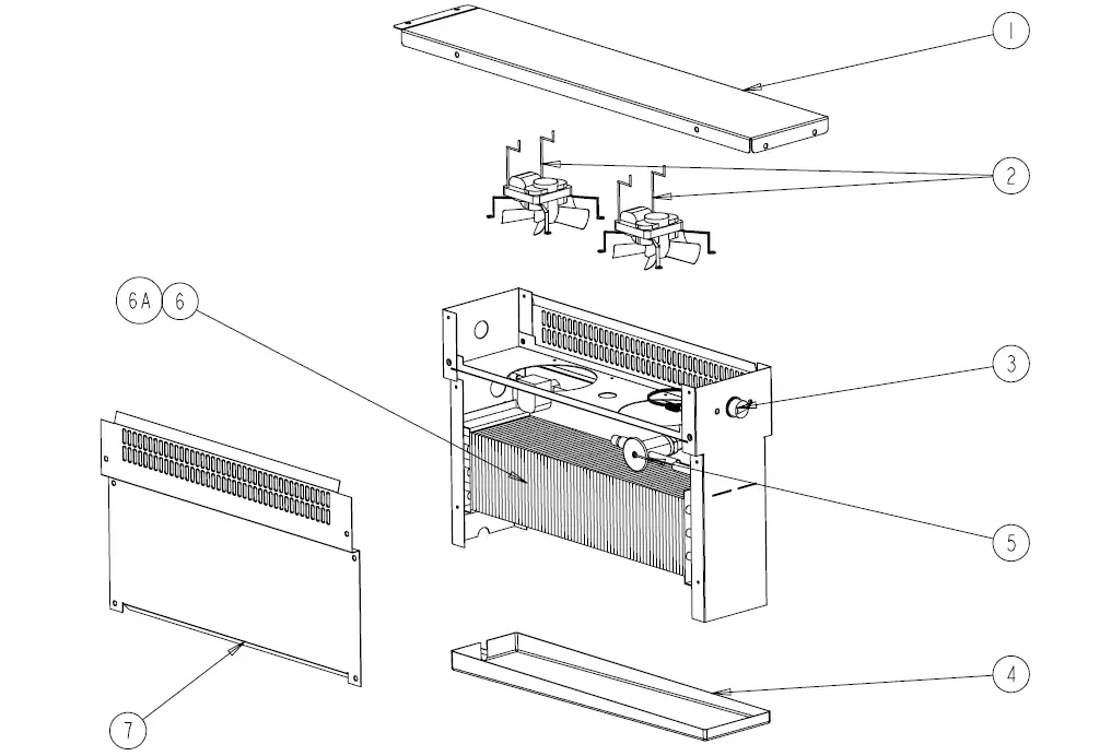
| ITEM | SERVICE PART | DESCRIPTION |
| 1 | RP BRK006 | Mounting Support Bracket for Coil Assembly |
| 2 | EL MTR2338 | Evaporator Fan Motor w/ blade (April 1998 – Present) |
| 3 | HD CNT200 | Dial Temperature Control |
| 4 | RP DRP107 | Evaporator drain pan –Plastic Bottom 18.25 X 4.25 (Ref only) |
| 5 | RF VLV200 | TXV Valve for Coil Assembly 134A |
| 6 | RP COI107 | Evaporator Coil |
| 6A | RP CSY0401 | Evaporator Coil Assembly, Refrigerated Units only |
| 7 | RP PNL107 | Shield Panel for Coil assembly |
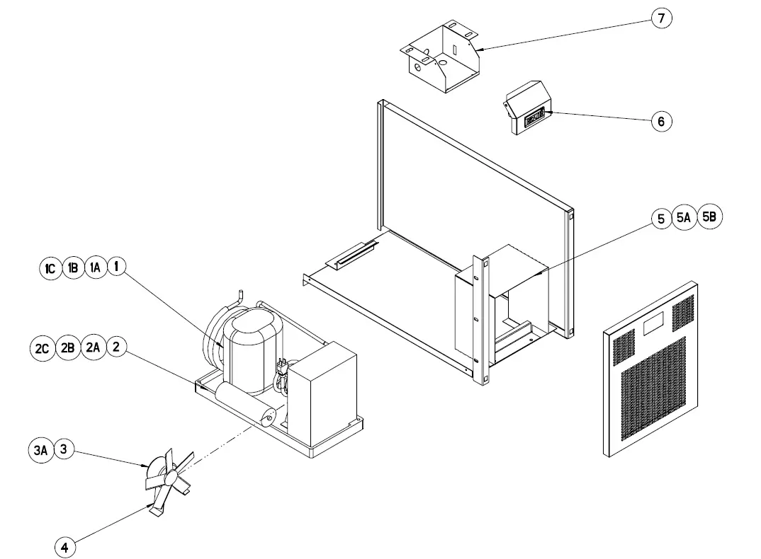
| ITEM | SERVICE PART | DESCRIPTION |
| 1 | RF CMP010-134 | Compressor, 20048SC |
| 1A | RF CMP020-134P | Compressor, 20072SC, 20078SC |
| 1B | RF CMP0104P | Compressor, 20105SC |
| 1C | RF CMP200-134P | Compressor, 20105SC-32, 20114SC |
| 2 | RF CON0004 | Condensing Unit, 20048SC |
| 2A | RF CON0113 | Condensing Unit, 20072SC, 20078SC |
| 2B | RF CON0006 | Condensing Unit, 20105SC |
| 2C | RF CON502 | Condensing Unit, 20105SC-32, 20114SC |
| 3 | RF ASY1200P | Condenser Fan Motor Assy, 20048SC, 20072SC, 20078SC – AFTER Jan 2013 |
| 3A | EL MTR0102 | Condenser Fan Motor, 20105SC, 20105SC-32 |
| 4 | RF BLD0101 | Condenser Fan Blade, 20048SC, 20072SC, 20078SC, 20105SC |
| 5 | RP SHD0505 | Condensing Unit Shroud, 20048SC |
| 5A | RP SHD0506 | Condensing Unit Shroud, 20072SC, 20078SC |
| 5B | RP SHD0507 | Condensing Unit Shroud, 20105SC |
| 6 | RP CNT0207 | Dixell Temperature Control for Rail |
| 7 | RP BRK0509 | Dixell Mounting Housing Bracket |
Wiring Diagram
Service Log
| Model No: | Purchased From: |
| Serial No: | Location: |
| Date Purchased: | Date Installed: |
| Purchase Order No: | For Service Call: |
| Date | Maintenance Performed | Performed By |


