
F4T/D4T Flex Module
Quick Start Guide
High Density Input/Output Modules
FMHA-_ _ _ _-_ _ _ _
![]()

0600-0096-0000 Rev. D Made in the U.S.A.![]()
November 2016
Safety Information
We use caution symbols where needed within this document t o draw your attention to import ant operational and safety information.
A ” CAUTION” safety alert appears with information that is import ant f or protecting your equipment and performance. Be especially careful t o read and follow all cautions t hat apply t o your application.
A ” WARNING” safety alert appears with information t hat is import ant f or protecting you, others and equipment f rom damage. Pay very close attention t o all warnings t hat apply t o your application.
The electrical hazard symbol, (a lightning bolt in a triangle) precedes an electric shock hazard CAUTION or WARNING safety statement . Further explanations follow:
| Symbol | Explanation |
CAUTION WARNING or Electrical Shock Hazard | CAUTION – Warning or Hazard that needs further explanation than label on unit can provide. Consult QSG for further information. |
Document Overview
The purpose of t his Quick St art Guide (QSG) is t o acquaint t he user wit h t he F4T/ D4T High Density (HD) Flex Modules and associated wiring.
Product Overview
Flex modules serve as t he interface bet ween real-world devices and t he F4T/ D4T system. The flex modules described in t his document offer various input and out put opt ions and greater density (more than 1) than the standard flex modules. With the except ion of t he Dual SSR module, all of these modules can be placed in any available slot.
Available F4T/D4T Literature and Resources
| Document Title and Part Number | Description |
| F4T Installation and Troubleshooting User Guide, part number: 0600-0092- 0000 | Provides detailed specifications and information regarding mounting the base, flex module wiring and troubleshooting. |
| F4T Setup and Operations User Guide, part number: 0600-0093-0000 | Explains how to configure and operate the device for an application using Composer software as well as the user interface (touch screen). Includes detailed descriptions of all device features and parameter settings. |
| D4T Installation and Troubleshooting User Guide, part number: 0600-0107- 0000 | Provides detailed specifications and information regarding mounting the base, flex module wiring and troubleshooting. |
| D4T Setup and Operations User Guide, part number: 0600-106-0000 | Explains how to configure the data logger for an application using the user interface and Composer software. Includes detailed descriptions of all data logger features and parameter settings. |
Installation and Wiring
To install the flex module:
- Note the part number to determine the number and type of inputs or outputs available to be connected in step 7.
- Turn off device power.
- Select a compatible base slot for the module. See the Flex Module-Slot Dependencies table below. If replacing a module, remove the old module.
- Affix corresponding slot number labels (provided) to the module and to the removable screw terminal block.
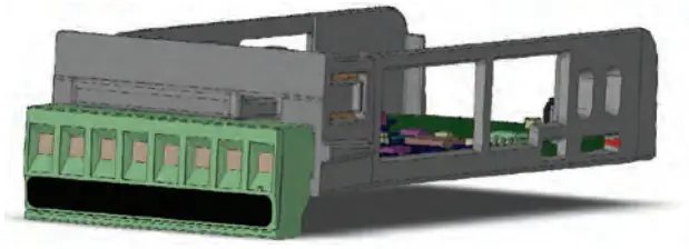
- With the component side of the module facing right (viewing the F4T/D4T from the rear) insert the module into the slot until it latches.
- Remove the screw terminal block from the module.
- Wire field devices to the appropriate terminals. Wiring details for each input and output are provided in the following sections.
- Reconnect the wired screw terminal block to the module. Be sure to reconnect the terminal block to the correct module.
- Restore power to the F4T/D4T.
Note:
If the flex module is a replacement with the same part number and slot position, the F4T/D4T uses it immediately when powered up. Otherwise, use Composer software to configure the F4T/D4T to expect and use the module.
| Flex Module – Slot Dependencies | ||||||
| Slot # | ||||||
| Module Type | 1 | 2 | 3 | 4 | 5 | 6 |
| Dual SSR * FMHA-K | Y | Y | N | Y | Y | N |
| Communications FMCA-(2) | N | N | N | N | N | Y |
| All Other Modules | Y | Y | Y | Y | Y | Y |
Y = Allowed N = Not allowed
* Reguires two adjacent slots
Module Characteristics
Description and Identification
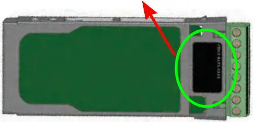
Many of the modules appear to look alike at first glance, therefore, it is always recommended that the module part number be verified prior to plugging it into any of the available slots in a base. Each module is identified with a part number located on the back side of the assembly next to the screw terminal block, as displayed in the graphic to the right.
F M H A – _ _ _ A – A _ _ _
Wiring
Prior to wiring any of the I/O modules described in this document, it is recommended that the warnings and notes listed below be reviewed.
CAUTION: ![]()
To prevent damage to the F4T/D4T, do not connect wires to unused terminals.
Note:
Maintain electrical isolation between the analog input, digital input-outputs, switched dc/open collector outputs and process outputs to prevent ground loops.
Note:
Modules IP10 when properly installed in base enclosure with slot caps in empty slots.
CAUTION: ![]()
Switching pilot duty inductive loads (relay coils, solenoids, etc.) with the mechanical relay, solid-state relay or open collector output options requires use of an R.C. suppressor for AC load or a diode for a DC load.
Note:
Wire size and torque for screw terminations:
- 0.0507 to 3.30 mm² (30 to 12 AWG) single-wire termination or two 1.31 mm² (16 AWG)
- 0.57 Nm (5.0 lb.-in.) torque
Input Connections
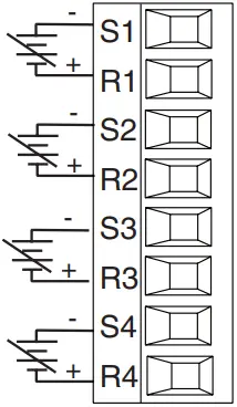
Thermocouple
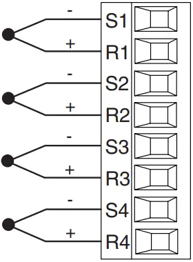
FMHA – [R] A A A – A _ _ _
- Grounded or ungrounded sensors, greater than 20MΩ input impedance, 2kΩ source resistance max
- 3µA open-sensor detection
- Thermocouples are polarity sensitive. The negative lead (usually red) must be connected to S terminal
- To reduce errors, the extension wire for thermocouples must be of the same alloy as the thermocouple
RTD
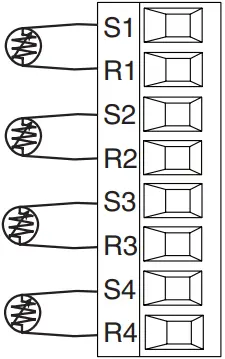
FMHA – [R] A A A – A _ _ _
- Platinum, 100 and 1kΩ @ 32°F (0°C) calibration to DIN curve (0.00385 Ω/Ω/°C)
- RTD excitation current of 0.09mA typical. Each ohm of lead resistance may affect the reading by 2.55°C for a 100Ω platinum sensor or 0.25°C for a 1kΩ sensor (see table to right)
| AWG | Ohms/ 1000ft |
| 14 | 2.575 |
| 16 | 4.094 |
| 18 | 6.510 |
| 20 | 10.35 |
| 22 | 16.46 |
| 24 | 26.17 |
| 26 | 41.62 |
| 28 | 66.17 |
Process
Volts Milliamps
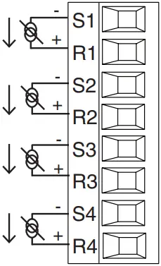
FMHA – [R] A A A – A _ _ _
- 0 to 20mA @ 100Ω input impedance
- 0 to 10V
 (dc) @ 20kΩ input impedance
 - 0 to 50mV(dc) @ 20MΩ input impedance
- Scalable
Potentiometer
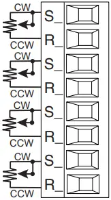
FM [M, L] A – [C, L, Y, R] _ _ A – A _ _ _
- Potentiometer: 0 to 1.2kΩ
Thermistor
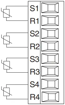
FMHA – [P] A A A – A _ _ _
- >20MΩ input impedance
- 0 to 40kΩ, 0 to 20kΩ, 0 to 10kΩ, 0 to 5kΩ
- 2.252kΩ and 10kΩ base at 77°F (25°C)
- User-selectable curves for Alpha Technics, Beta THERM and YSI
- User-scaling support for Steinhart-Hart coefficients
| Thermistor Curve Setting | Base R @ 25 ºC | Alpha Technics | Beta Therm | YSI |
| Curve A | 2.252k | Curve A | 2.2k3A | 004 |
| Curve B | 10k | Curve A | 10k3A | 016 |
| Curve C | 10k | Curve C | 10k4A | 006 |
| Custom | Use Steinhart-Hart equation coefficients (A, B and C) from thermistor manufacturer corresponding to the terms of the Steinhart-Hart equation: 1 / T = A + Bln(R) + C (ln(R))³ | |||
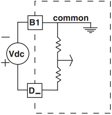
Six Digital Inputs
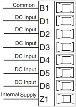
FMHA – [C] A A A – A _ _ _
- Voltage
– Max. input 36V at 3mA
– Input inactive when ≤ 2V
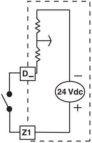
– Input active when ≥ 3V at 0.25mA - Dry Contact
– Input inactive when ≥ 500Ω
– Input active when ≤ 100Ω
– Max. short circuit 13mA
FMHA – [C] A A A – A _ _ _
Voltage Input Dry Contact
Output Connections
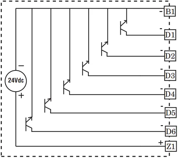
Six Digital Outputs
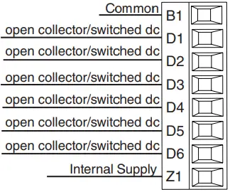
Open Collector
- Maximum switched open collector voltage is 32V (dc)
- 400mA, maximum open circuit voltage of 25V (dc), typical 8V (dc) at 80mA
- Maximum output sink current per output is 1.5A (external class 2 or SELV* supply required)
- Total sink current for all outputs not to exceed 8A
- Do not connect outputs in parallel
* Safety Extra Low Voltage
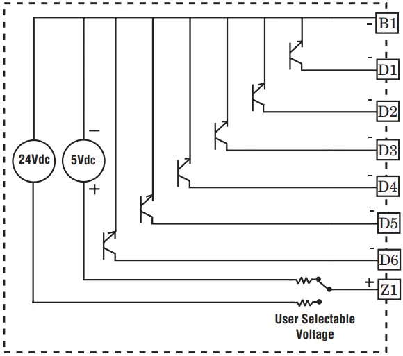
Switched DC
- User selectable voltage, 5V (dc) at 130mA or 19 to 22V (dc) at 80mA
FMHA – [C] A A A – A _ _ _
Open Collector Outputs
Switched DC Outputs
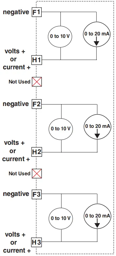
Tri-Process/Retransmit Outputs
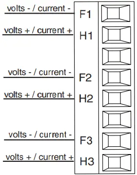
FMHA – [F] A A A – A _ _ _
- 0 to 20mA into 400Ω maximum load
- 0 to 10V (dc) into 4 kΩ minimum load
- Outputs are scalable
- Output supplies power
- Each output can be independently set for voltage or current
- Output may be used as retransmit or control
Four Mechanical Relays, Form A
Note:
Not 60730 compliant.
FMHA – [J] A A A – A _ _ _
- 5A at 240V~ (ac) or 30V (dc) maximum resistive load
- 20mA at 24V minimum load
- 125 VA pilot duty @ 120/240V~ (ac), 25 VA at 24V~ (ac)
- 100,000 cycles at rated load
- Output does not supply power.
- For use with ac or dc
- See Quencharc note
*Dual 10A Solid-State Relays, Form A
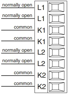
FMHA – [K] A A A – A _ _ _
- 10A at 20 to 264V~ (ac) maximum resistive load
- 10A per output at 240V~ (ac), max. 20A per card at 122°F (50°C), max. 12A per card at 149°F (65°C)
- Opto-isolated, without contact suppression
- Maximum off state leakage of 105µA
- Output does not supply power
- Do not use on dc loads.
- Requires two slots
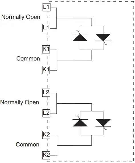
*Note:
This module requires 2 slots, therefore it cannot be placed in slot 3 or 6.
Note:
Not 60730 compliant.
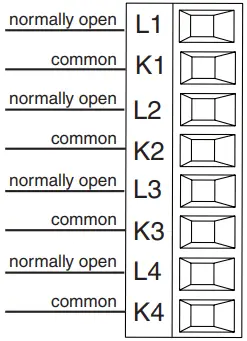
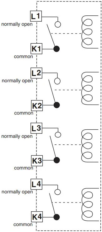
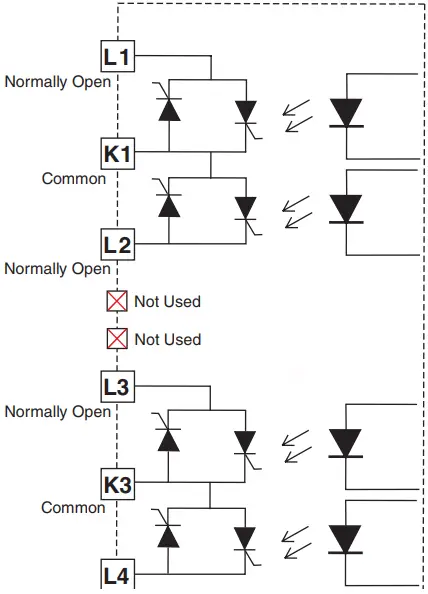
Four 2A Solid-State Relays, Form A
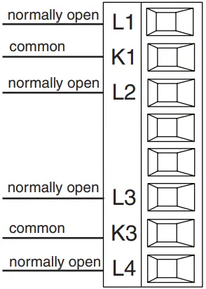
FMHA – [L] A A A – A _ _ _
- 2A at 20 to 264V~ (ac) maximum resistive load
- 50 VA 120/240V~ (ac) pilot duty
- Optical isolation, without contact suppression
- Maximum off state leakage of 105µA
- Output does not supply power.
- Do not use on dc loads.
- N.O., COM, N.O wiring (shared common) between each set of outputs.
- See derating curve below for maximum current output.
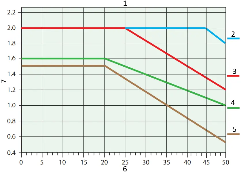
- Quad 2 Amp SSR Derating Curve All Outputs 100% Duty Cycle
- F4T/D4T with 2 FMs: 1 quad input and 1 quad 2A SSR FM. Outputs 1 and 3 on.
- F4T/D4T with 2 FMs: 1 quad input and 1 quad 2A SSR FM. All outputs on.
- F4T/D4T with 5 FMs: 1 quad 2A SSR.
- F4T/D4T with 6 FMs: 1 quad 2A SSR.
- Ambient Temperature (°C)
- Amps per Each SSR
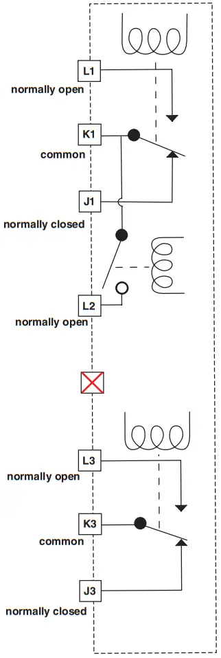
3 Mechanical Relays, 2 Form C, 1 Form A
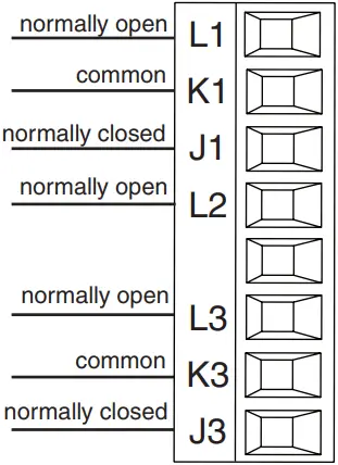
FMHA – [B] A A A – A _ _ _
- 5A at 24 to 240V~ (ac) or 30V (dc) maximum resistive load
- 125 VA pilot duty 120/240V~ (ac) 25 VA at 24V~ (ac)
- Output does not supply power
- Form A relay shares common with one Form C relay.
- See Quencharc note
Warranty
F4T/D4T Flex modules are manufactured by ISO 9001 registered processes and are backed by a three-year warranty to the first purchaser for use, providing that the modules have not been misapplied.
(CST)
This F4T/D4T Quick Start Guide (QSG) is copyrighted by Watlow Electric Manufacturing Company, © November 2016 with all rights reserved.
| Symbol | Explanation |
 | Unit is compliant with European Union directives. See Declaration of Conformity for further details on directives and standards used for compliance. |
 | Unit has been reviewed and approved by CSA International for use as Temperature Indicating-Regulating Equipment per CSA C22.2 No. 24. See: www.csa-international.org |
 | Recognized component UL Files E185611 Process Control Equipment and E43684 Automatic Temperature Sensing Control Integrated Equipment, see conditions of acceptability. |
Specifications
| Input Type | Max Error @ 25 Deg C | Accuracy Range | Operating Range | Units | ||
| Low | High | Low | High | |||
| *J | ±1.75 | 0 | 750 | -210 | 1200 | Deg C |
| *K | ±2.45 | -200 | 1250 | -270 | 1371 | Deg C |
| *T (-200 to 350) | ±1.55 | -200 | 350 | -270 | 400 | Deg C |
| N | ±2.25 | 0 | 1250 | -270 | 1300 | Deg C |
| *E | ±2.10 | -200 | 900 | -270 | 1000 | Deg C |
| R | ±3.9 | 0 | 1450 | -50 | 1767 | Deg C |
| S | ±3.9 | 0 | 1450 | -50 | 1767 | Deg C |
| B | ±2.66 | 870 | 1700 | -50 | 1816 | Deg C |
| C | ±3.32 | 0 | 2315 | 0 | 2315 | Deg C |
| D | ±3.32 | 0 | 2315 | 0 | 2315 | Deg C |
| F (PTII) | ±2.34 | 0 | 1343 | 0 | 1343 | Deg C |
| *RTD, 100Ω | ±2.00 | -200 | 800 | -200 | 800 | Deg C |
| RTD, 1kΩ | ±2.00 | -200 | 800 | -200 | 800 | Deg C |
| mV | ±0.05 | 0 | 50 | – – – | – – – | mV |
| Volts | ±0.01 | 0 | 10 | – – – | – – – | Volts |
| mAdc | ±0.02 | 2 | 20 | – – – | – – – | mA DC |
| mAac | ±5 | -50 | 50 | – – – | – – – | mA AC |
| Potentiometer 1k range | ±1 | 0 | 1000 | – – – | – – – | Ohms |
*NSF approved inputs
| Thermistor Input | ||||
| Input Type | Max Error @ 25 Deg C | Accuracy Range | Units | |
| Low | High | |||
| Thermistor, 5k range | ±5 | 0 | 5000 | Ohms |
| Thermistor, 10k range | ±10 | 0 | 10000 | Ohms |
| Thermistor, 20k range | ±20 | 0 | 20000 | Ohms |
| Thermistor, 40k range | ±40 | 0 | 40000 | Ohms |
Declaration of Conformity
Series EZ-ZONE® Flex Modules
WATLOW Electric Manufacturing Company ISO 9001since 1996.
1241 Bundy Blvd.
Winona, MN 55987 USA
| Declares that the following products: | |
| Designation: | Series EZ-ZONE® Flex Modules |
| Model Numbers: | FMLA-(LAJ, LCJ, LEJ, MAJ, MCJ, MEJ, YEB¹ )A¹ -A¹ (A¹, F¹, B¹, G¹ )X¹X¹ FMMA-X1(A1 ,C1 ,E,F1 ,K)(A1 ,C1 ,H,J,K)A¹ -A¹ (A¹, F¹, B¹, G¹ )X¹X¹ FMHA-(R¹ ,P¹ ,C¹ ,F¹ ,B¹ ,J,K,L¹ )A¹ A¹ A¹ -A¹ (A¹ ,F¹ ,B¹ ,G¹ )X¹X¹ ¹FMCA-XAAA-A(A,F,B,G)XX; Note: X¹ = Any letter or number |
| Classification: | FMLA, FMMA and FMHA are Process Control modules, FMCA are Communication modules; Modules are Integrated Controls in either EZ-ZONE® CC, F4T or D4T Bases; Modules are IP10 when properly installed. |
| Rated Voltage and Frequency: | Relay, SSR or No-Arc Control outputs 24 to 240 V~ (ac) 50/60 Hz, Switched DC, Process and communications; low voltage SELV |
| Rated Power Consumption: | See manual for de-rating at increased temperatures. No-arc relays 15A 1.C, Dual SSR module 1.C 10A each output, Mechanical relay 5A 125 VA, 25 VA at 24 V~ (ac) 1.B, Discreet SSR 1/2A 1.C 20VA, Quad SSR 1.C 1.5A 50 VA, Hex I/O ELV 1.5A, all others SELV limited energy. |
Flex Modules are considered components and have no function in and of themselves, it is only when installed in a Watlow EZ-ZONE® CC, Series F4T or Series D4T Base enclosure that they have useful function. Modules were tested as parts of these systems for compliance with the following directives.
2014/30/EU Electromagnetic Compatibility Directive
| EN 61326-1:2013 | Electrical equipment for measurement, control and laboratory use – EMC requirements (Industrial Immunity, Class B Emissions). |
2014/35/EU Low-Voltage Directive
| EN 61010-1:2010 All options compliant | Safety Requirements of electrical equipment for measurement, control and laboratory use. Part 1: General requirements |
| EN 60730-1:2011 EN 60730-2-9:2010 | Automatic electrical controls for household and similar use – Particular requirements for temperature sensing controls. |
| ¹ Food Service Compliant options. | Only certain output options comply with 60730 spacing and dielectric requirements, see order information for compatible models. |
Compliant with 2011/65/EU RoHS2 Directive
Per 2012/19/EU W.E.E.E Directive  Please Recycle Properly.
See the Declarations of Conformity for Watlow EZ-ZONE® CC, Series F4T and Series D4T models for further details on standards used for compliance.
Joe Millanes
Name of Authorized Representative
Directory of Operations
Title of Authorized Representative

Signature of Authorized Representative
Winona, Minnesota, USA
Place of Issue
April 20, 2016
Date of Issue
1.888.610.7664 ![]() www.calcert.com [email protected]
www.calcert.com [email protected]


