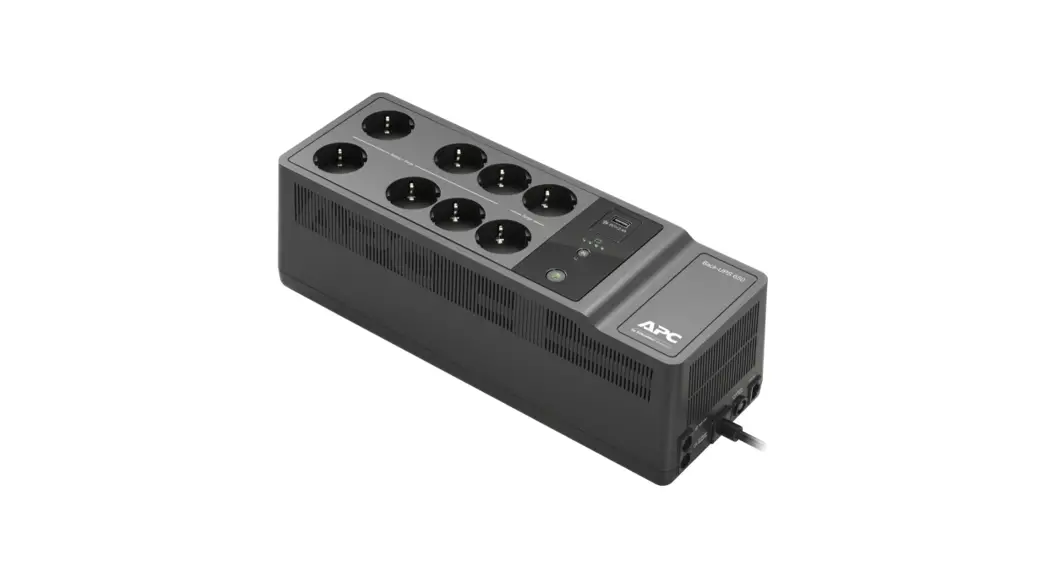
![]() BE650G2-SP Back UPS
BE650G2-SP Back UPS
User Manual
Important Safety Information
SAVE THESE INSTRUCTIONS – This manual contains important instructions that should be followed during installation and maintenance of the Back-UPS and batteries.
Read these instructions carefully and look at the equipment to become familiar with the device before trying to install, operate, service or maintain it. The following special messages may appear throughout this document or on the equipment to warn of potential hazards or to call attention to information that clarifies or simplifies a procedure.![]() The addition of this symbol to either a “Danger” or “Warning” safety label indicates that an electrical hazard exists which will result in personal injury if the instructions are not followed.
The addition of this symbol to either a “Danger” or “Warning” safety label indicates that an electrical hazard exists which will result in personal injury if the instructions are not followed.![]() This is the safety alert symbol. It is used to alert you to potential personal injury hazards. Obey all safety messages that follow this symbol to avoid possible injury or death.
This is the safety alert symbol. It is used to alert you to potential personal injury hazards. Obey all safety messages that follow this symbol to avoid possible injury or death.![]() DANGER
DANGER
DANGER indicates a hazardous situation which, if not avoided, will result in death or serious injury.![]() WARNING
WARNING
WARNING indicates a hazardous situation which, if not avoided, could result in death or serious injury.![]() CAUTION
CAUTION
CAUTION indicates a hazardous situation which, if not avoided, could result in minor or moderate injury.
NOTICE
NOTICE is used to address practices not related to physical injury.
Product Handling Guidelines![]()
Safety and General Information
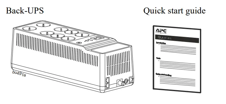
Inspect the package contents upon receipt. Notify the carrier and dealer if there is any damage.
- This UPS is for indoor use only.
- Do not operate this UPS in direct sunlight, in contact with fluids, or where there is excessive dust or high humidity.
- Do not operate the UPS near open windows or doors.
- Be sure the air vents on the UPS are not blocked. Allow adequate space for proper ventilation.
Note: Allow a minimum of 20 cm clearance on both front and rear sides of the UPS. - Environmental factors impact battery life. Elevated ambient temperatures, poor quality utility power, and frequent discharges will shorten battery life. Follow the battery manufacturer recommendations.
- Connect the UPS power cable directly to a wall outlet. Do not use surge protectors or extension cords.
- The UPS cord shall be connected to an earthed mains socket outlet for safety reasons.
Battery safety
- Servicing of batteries should be performed or supervised by personnel knowledgeable about batteries and required precautions.
- APC by Schneider Electric uses Sealed Maintenance-Free Lead Acid batteries. Under normal use and handling, there is no contact with the internal components of the batteries. Over charging, over heating or other misuse of batteries can result in leakage of battery electrolyte. Released electrolyte is toxic and may be harmful to the skin and eyes.
- CAUTION: Before installing or replacing the batteries, remove conductive jewelry such as chains, wrist watches, and rings. High energy through conductive materials could cause severe burns.
- CAUTION: Do not dispose of batteries in a fire. The batteries may explode.
- CAUTION: Do not open or mutilate batteries. Released material is harmful to the skin and eyes and may be toxic.
- CAUTION: A battery can present a risk of electrical shock and high short-circuit current. Failed batteries can reach temperatures that exceed the burn thresholds for touchable surfaces. The following precautions should be observed when working on batteries:
– Disconnect the charging source prior to connecting or disconnecting battery terminals.
– Do not wear any metal objects including watches and rings.
– Do not lay tools or metal parts on top of batteries.
– Use tools with insulated handles.
– Wear rubber gloves and boots.
– Determine if battery is either intentionally or inadvertently grounded. Contact with any part of a grounded battery can result in electric shock and burns by high short-circuit current. The risk of such hazards can be reduced if grounds are removed during installation and maintenance by a skilled person.
Inventory
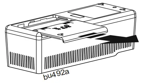
 Connect the Battery
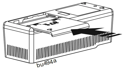
- Remove the “Stop! Connect Battery” label from the top cover.
- Invert the Back-UPS. Press the battery compartment cover and release the tabs. Slide open the battery cover.

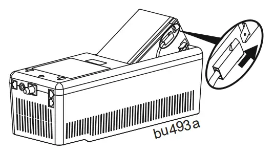
- Connect the battery cable securely to the battery terminal.
Note: It is normal for small sparks to be seen when the battery cable is connected to the battery terminal.
- Reinstall the battery compartment cover. Be sure that the release tabs lock into place.

Wall Mount Installation![]() CAUTION
CAUTION
RISK OF FALLING EQUIPMENT
Always practice safe lifting techniques adequate for the weight of the equipment.
Failure to follow these instructions can result in minor or moderate injury and equipment damage.
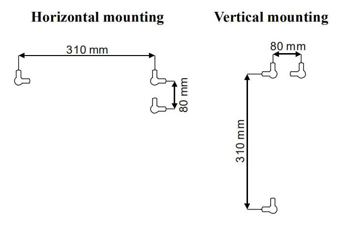
- Secure 3 screws of appropriate size (not supplied)as per dimensions shown in the horizontal/vertical mounting illustrations.
- Allow the screw to protrude out 8mm from the wall.
- Mount the Back-UPS on to the screws.
Panel Features 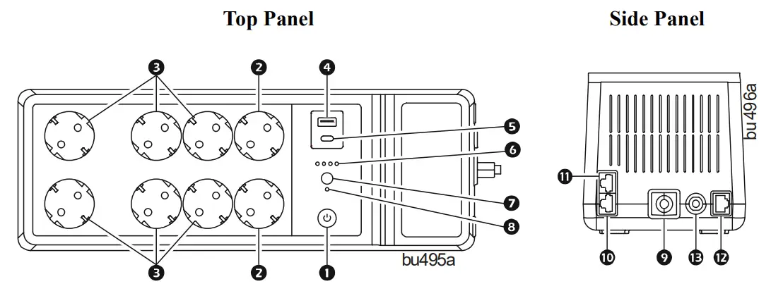
| 1 | POWER ON/OFF button and LED | Use to switch the Back-UPS on or off. The LED illuminates green to indicate that power is supplied to the connected equipment both on utility power and on battery. See “Status Indicators” on page 9 for other status of the Power on/off LED. |
| 2 | Surge protection outlets | Surge protection outlets provide protection to connected equipment from power surges or spikes, when the Back-UPS is turned on and connected to utility power. Connect peripheral devices (such as printer, scanner, etc.) that do not need to remain on during power outages or brownout condition, to these outlets. |
| 3 | Battery backup + surge protection outlets | Battery backup outlets provide power from the battery for a limited period of time during power outage, or brownout condition. Battery backup outlets provide protection to connected equipment from power surges or spikes, when the Back-UPS is turned on and connected to utility power. Connect a computer, monitor and other peripheral devices which need to remain on during power outages or brownout condition, to these outlets. |
| 4 | Type A USB charging port | This USB charging port provides a maximum of 2.4 A DC power. The port will charge the connected equipment when the Back-UPS is turned on. |
| 5 | Type C USB charging port (BE850G2-SP only) | |
| 6 | Battery status LED | The four Battery status LEDs indicate the remaining runtime. When battery is fully charged, all four LEDs illuminate. Refer “Status Indicators” on page 9 for details. |
| 7 | MUTE button | Press MUTE button to Enable or Disable the mute function. |
| 8 | Mute status LED | Illuminates when the mute function is enabled. |
| 9 | Input power cord | Connect the Input power cord to a wall outlet (utility power). Do not connect the power cord to a surge protector or power strip. |
| 10 | DSL/modem network/fax port | Connect a DSL or Dial-up modem, Phone, Fax machine, or 10/100 Base-T Ethernet equipment. Note: Do not connect the UPS telephone protection ports to both the telephone and network system cables at the same time. |
| 11 | Wall outlet | Connect the Back-UPS to a data line wall outlet. |
| 12 | Data port | Connect a RJ45/USB cable (not supplied) to connect the Back-UPS to a computer for installing the software. See “UPS Self Test” on page 8 for details. |
| 13 | Circuit breaker | Trips when the Back-UPS experiences an overload condition. |
Specifications
| BE650G2-SP | BE850G2-SP | ||
| Input | Voltage | 220 – 240 Vac | |
| Frequency | 47 to 63 Hz | ||
| Brownout Transfers | 180 Vac Typical | ||
| Over-voltage Transfer | 266 Vac Typical | ||
| Output | UPS Capacity | 650 VA, 400 W | 850 VA, 520 W |
| Battery Backup outlets | 2.96 A | 3.87 A | |
| Total Amperage | 6 A | ||
| Voltage – On Battery | 230 Vac ± 8% | ||
| Frequency – On Battery | 50/60 Hz ± 1 Hz | ||
| Transfer Time | 6 milliseconds Typical, 10 milliseconds maximum | ||
| USB Port | * Charging Rating | 5 V; 2.40 A | |
| Charger compatibility | USB Battery Charging Specification 1.2 | ||
| * Power output is dependent on the power drawn by the connected device. Check with the device manufacturer to understand the maximum charging current for a given USB specification. | |||
| Protection and Filtering | AC Surge Protection | Full time, 310 Joules | |
| EMI/RFI Filter | Full time | ||
| Utility Power Input | Resettable circuit breaker | ||
| Battery | Type | Sealed, maintenance-free, lead acid 12 V | |
| Average Life | 3 – 5 years, depending upon the number of discharge cycles and environmental temperature | ||
| Charging Time | 16 hours. Using the USB port while charging the battery will increase the battery charging time | ||
| Physical | Net Weight | 8.8 lb (4 kg) | 9.9 lb (4.5 kg) |
| Dimensions L x W x H | 14.4 in x 5.1 in x 4.7 in 36.5 cm x 13 cm x 12 cm | ||
| Environmental | Operating Temperature | 32 ºF to 104 ºF (0 ºC to 40 ºC) | |
| Storage Temperature | 5 ºF to 113 ºF (-15 ºC to 45 ºC) | ||
| Operating Relative Humidity | 0 to 95% non-condensing humidity | ||
| Pollution degree | 2 | ||
| International Protection Code | IP20 | ||
| Overvoltage category | II | ||
| Applicable power grid power distribution system | TN Power system | ||
| Applicable standard | IEC 62040-1 | ||
Turn On the Back-UPS
Press the POWER ON/OFF button located on the top of the Back-UPS. The Power on/off LED will illuminate green and a single short beep will indicate that the Back-UPS is on and providing protection to the connected equipment. The Back-UPS battery charges to capacity during the first 24 hours while connected to the utility power. The Back-UPS battery will charge while the Back-UPS is turned on or off and as long as it is connected to utility power.
Do not expect the battery to run for its expected capacity during the initial charge period. The UPS will have full runtime capability after the initial 24 hour charging period.
Turn Off the Back-UPS
Press the POWER ON/OFF button for at least 2 seconds to turn off the Back-UPS. At the first beep, release the button and the UPS will turn off.
A 2 second delay has been added to mitigate unintentional contact with the POWER ON/OFF button.
Mute
The audible alarms of the Back-UPS can be muted. Press the MUTE button to enable or disable the mute function. The Mute status LED illuminates when the mute function is enabled.
UPS Self Test
Press and hold the POWER ON/OFF button for 4 to 8 seconds to initiate the UPS Self Test.
PowerChute ™ Personal Edition Software
Overview
Use PowerChute Personal Edition software to configure the UPS settings, help protect your computer and other equipment during a utility power outage. During a power outage, PowerChute will save any open files on your computer and shut it down. When utility power is restored, it will restart the computer.
Note: PowerChute is only compatible with a Windows operating system. If you are using Mac OSX, use the native shutdown feature to help protect your system. See the documentation provided with your computer.
Installation
Note: To reduce electronic waste and help protect the environment, USB cables are no longer shipped in every box. Order the cable free of charge at https://www.apc.com/usbcable.
Use the USB cable to connect the Data port on the UPS to the USB port on your computer. Download PowerChute™ Personal Edition Software from www.apc.com/pcpe. Select the appropriate operating system and follow directions to download the software.
Status Indicators
| Visual indicator | Audible indicator | Condition | Audible indicator terminates |
| Power on/off LED illuminates green | None | Power On – The Back-UPS is supplying utility power to the connected equipment. | Not applicable. |
| Power on/off LED flashes green twice every 2 seconds | 4 beeps approx. every 40 seconds. | On Battery – The Back-UPS is supplying battery power to the battery backup outlets. | Beeping stops when utility power is restored or the Back-UPS is turned off. |
| Power on/off LED flashes green in quick succession. | Rapid beeping (1 beep every 0.5 second) | Low Battery notification The Back-UPS is supplying battery power to the battery backup outlets and the battery is nearing a total discharge state. | |
| Power on/off LED flashes green in quick succession. | 1 beep every 4 seconds | Low Battery shutdown – The battery has been completely discharged while the Back-UPS is on battery, the Back-UPS will shutdown. | Beeping stops when utility power is restored or the Back-UPS is turned off. |
| None | Sleep Mode – The Back-UPS has shutdown and will return to normal operation once utility power is restored. | Not applicable. | |
| Power on/off LED flashes red and Battery status LED flashes green in quick succession. | Constant tone | Battery disconnected. | Back-UPS is turned off. |
| Power on/off LED flashes green and red alternately | Constant tone | Replace battery – The battery needs to be charged or replaced. | Back-UPS is turned off. |
| Visual indicator | Audible indicator | Condition | Audible indicator terminates |
| Power on/off LED does not illuminate | Constant tone | Overload shutdown – An overload condition in one or more of the battery back up outlets when the Back-UPS is operating on battery power. | Back-UPS is turned off. |
| Power on/off LED flashes green and amber alternately | None | USB error detected – A short circuit or an internal error has been detected. | Not applicable. |
| Mute status LED illuminates | None | Mute function enabled. | Not applicable. |
| Mute status LED does not illuminate | None | Mute function disabled. | Not applicable. |
| When the Back-UPS is operating on battery power and the battery is getting discharged | |||
| First Battery status LED illuminates | None | Remaining battery capacity is 0% to 24%. | Not applicable. |
| First two Battery status LEDs illuminate | None | Remaining battery capacity is 25% to 49%. | Not applicable. |
| First three Battery status LEDs illuminate | None | Remaining battery capacity is 50% to 74%. | Not applicable. |
| All 4 Battery status LEDs illuminate | Non | Remaining battery capacity is 75% to 100%. | Not applicable. |
| When the Back-UPS is on utility power and the battery is charging | |||
| First Battery status LED flashes and the other three Battery status LED are not illuminated | None | Battery charge is 0% to 24%. | Not applicable. |
| First Battery status LED illuminates, second Battery status LED flashes, and other two Battery status LEDs are not illuminated | None | Battery charge is 25% to 49%. | Not applicable. |
| First two Battery status LEDs illuminate, third Battery status LED flashes and fourth Battery status LED not illuminated | None | Battery charge is 50% to 74%. | Not applicable. |
| Visual indicator | Audible indicator | Condition | Audible indicator terminates |
| First three Battery status LEDs illuminate and fourth Battery status LED flashes | None | Battery charge is 75% to 100%. | Not applicable. |
| All four Battery status LEDs illuminate | None | Battery fully charged and Back-UPS is on utility power. | Not applicable. |
Voltage Sensitivity Adjustment (Optional)
The Back-UPS will switch to battery power if the utility input voltage level or distortions go out of range or if the utility power is experiencing voltage fluctuations, to help protect connected equipment. In situations where either the Back-UPS or the connected equipment is too sensitive for the utility input voltage level, it is necessary to adjust the transfer voltage.
- Turn off the Back-UPS while connected to a wall outlet.
- Press and hold the POWER ON/OFF button for 10 seconds. The Power On/Off LED will alternate green and red to indicate that the Back-UPS is in Program mode.
- The Power On/Off LED will flash either green, amber, or red to indicate the current sensitivity level. Refer to the table below for an explanation of the transfer voltage sensitivity levels.
- To exit Program mode wait five seconds and all LED indicators will turn off. Program mode is no longer active.
| LED Flashes | Sensitivity Setting | Input Voltage Range (Utility Power Operation) | Recommended Use |
| Green | LOW | 160 Vac to 278 Vac | Use this setting when connected equipment is less sensitive to fluctuations in voltage or waveform distortions. |
| Red | MEDIUM | 180 Vac to 266 Vac | Factory default setting. Use this setting under normal conditions. |
| Amber | HIGH | 196 Vac to 256 Vac | Use this setting when connected equipment is sensitive to voltage and waveform fluctuations. |
Replace Battery
CAUTION
RISK OF HYDROGEN SULPHIDE GAS AND EXCESSIVE SMOKE
- Replace the battery at least every 5 years or at the end of its service life, whichever is earlier.
- Replace the battery immediately when the UPS indicates battery replacement is necessary.
- Replace batteries with the same number and type of batteries as originally installed in the equipment.
- Replace the battery immediately when the UPS indicates a battery over-temperature condition or when there is evidence of electrolyte leakage. Power off the UPS, unplug it from the AC input, and disconnect the batteries. Do not operate the UPS until the batteries have been replaced.
Failure to follow these instructions could result in minor or moderate injury and equipment damage.
Replacement batteries can be ordered through the APC by Schneider Electric Web site, www.apc.com. .
| Model | Replacement battery part number |
| BE650G2-SP | APCRBC110 |
| BE850G2-SP | RBC17 |
![]() Deliver the used battery to a recycling facility.
Deliver the used battery to a recycling facility.
Troubleshooting
| Problem | Possible Cause | Corrective Action |
| The Back-UPS will not turn on. | The Back-UPS has not been turned on. | Press the POWER ON/OFF button. |
| The Back-UPS is not connected to utility power, or there is no utility power available at the wall outlet, or the utility power is experiencing a brownout or over voltage condition. | Be sure that the power cord is securely connected to the wall outlet, and that the utility power is available at the wall outlet. Where applicable, be sure that the wall outlet is switched on. |
| Problem | Possible Cause | Corrective Action |
| The Back-UPS will not turn on. | Back-UPS circuit breaker tripped. | 1. Disconnect all nonessential equipment connected to the outlets. 2. Reset the circuit breaker by pushing in the circuit breaker button fully inwards until it latches. 3. If the circuit breaker resets, switch On the Back-UPS and reconnect one equipment at a time to the Back-UPS. 4. If the circuit breaker trips again, it is likely that one of the connected devices is causing the overload. |
| The Back-UPS is on, the Power on/off LED flashes red and the unit emits a constant tone. | The battery is disconnected. | Connect the battery. Refer to “Connect the Battery” on page 3 for details. |
| Connected equipment loses power. | A Back-UPS overload condition has occurred. | • Disconnect all nonessential equipment connected to the outlets. Reconnect one equipment at a time to the Back-UPS. • Be sure that at least one Battery status LED is illuminating. Charge the battery for 16 hours to make sure it is fully charged. • If the overload condition still occurs, replace the battery. |
| The Back-UPS battery is completely discharged. | Connect the Back-UPS to utility power and allow the battery to recharge for 16 hours. | |
| PowerChute software has performed a shutdown due to a power outage. | This is a normal Back-UPS operation. | |
| Connected equipment does not accept the step-approximated sine waveform from the Back-UPS. | The output waveform is intended for computers and peripheral devices. It is not intended for use with motor driven equipment. | |
| The Back-UPS may require service. | Contact Schneider Electric Technical Support for more in-depth troubleshooting. |
Warranty
Register your product on-line. http://warranty.apc.com
The standard warranty is three (3) years from the date of purchase valid in European Community. For all other regions, the standard warranty is two (2) years from the date of purchase. Schneider Electric IT (SEIT) standard procedure is to replace the original unit with a factory reconditioned unit.
Customers who must have the original unit back due to the assignment of asset tags and set depreciation schedules must declare such a need at first contact with an SEIT Technical Support representative. SEIT will ship the replacement unit once the defective unit has been received by the repair department, or cross ship upon the receipt of a valid credit card number. The customer pays for shipping the unit to SEIT. SEIT pays ground freight transportation costs to ship the replacement unit to the customer.
Service
If the unit requires service, do not return it to the dealer. Follow these steps:
- Review the Troubleshooting section of the manual to eliminate common problems.
- If the problem persists, contact Schneider Electric IT (SEIT) Customer Support through the Web site, www.apc.com.
a. Note the model number and serial number and the date of purchase. The model and serial numbers are located on the rear panel of the unit and are available through the LCD display on select models.
b. Call SEIT Customer Support and a technician will attempt to solve the problem over the phone. If this is not possible, the technician will issue a Returned Material Authorization Number (RMA#).
c. If the unit is under warranty, the repairs are free.
d. Service procedures and returns may vary internationally. Refer to the APC by Schneider Electric Web site for country specific instructions. - Pack the unit in the original packaging whenever possible to avoid damage in transit. Never use foam beads for packaging. Damage sustained in transit is not covered under warranty.
- Always DISCONNECT THE UPS BATTERIES before shipping. The United States Department of Transportation (DOT), and the International Air Transport Association (IATA) regulations require that UPS batteries be disconnected before shipping. The internal batteries may remain in the UPS.
- Write the RMA# provided by Customer Support on the outside of the package.
- Return the unit by insured, pre-paid carrier to the address provided by Customer Support
APC by Schneider Electric IT Customer Support Worldwide
For country specific customer support, go to the APC by Schneider Electric Web site, www.apc.com.
![]() © 2022 APC by Schneider Electric. APC, the APC logo, Back-UPS, and
© 2022 APC by Schneider Electric. APC, the APC logo, Back-UPS, and
PowerChute are owned by Schneider Electric Industries S.A.S., or their affiliated
companies. All other trademarks are property of their respective owners.
990-91290A
02/2022


