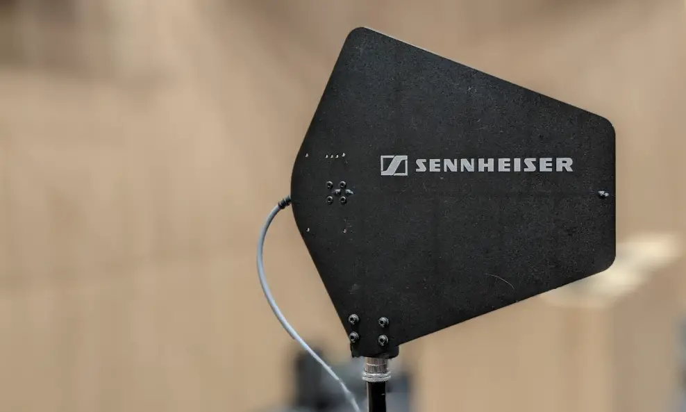
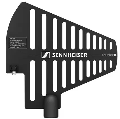
SENNHEISER SEADPUHF4701 ADP UHF Antenna Splitter
EW-D ASA antenna splitter
Frequency ranges
- EW-D ASA (Q-R-S): 470 – 694 MHz
- EW-D ASA CN/ANZ (Q-R-S): 470 – 694 MHz
- EW-D ASA (T-U-V-W): 694 – 1075 MHz
- EW-D ASA (X-Y): 1350 – 1805 MHz
EW-D ASA antenna splitter
2 x 1:4 or 1 x 1:8, active
Gain
- in A – out A: 0 ± 1 dB
- in A – out A1 … A4: 0 ± 1 dB
- in B – out B1 … B4: 0 ± 1 dB
IIP3
- > 25 dBm
Impedance
- 50 Ω
Reflection loss
- 10 dB (all RF outputs)
Operating voltage
- DC +12 V from NT 12-35 CS power supply unit
Current consumption
- 210 mA
Total current consumption
- max. 3 A (with 4 EW-D EM and connected EW-D AB)
Supply for antenna boosters at ANT RF in A and ANT RF in B
- DC 12 V
- 320 mA
Supply for receivers at A1 to A4
- DC 12 V
- Typically 350 mA, max. 500 mA
Relative humidity
- 5 – 95%
Operating temperature range
- -10 °C – +55 °C (14 °F – 131 °F)
Storage temperature range
- -20 °C – +70 °C (-4 °F – 158 °F)
Dimensions
- Approx. 212 x 168 x 43 mm
Weight
- Approx. 1100 g
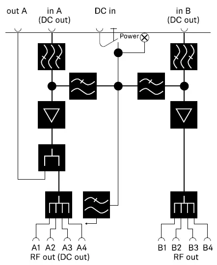
Block diagram
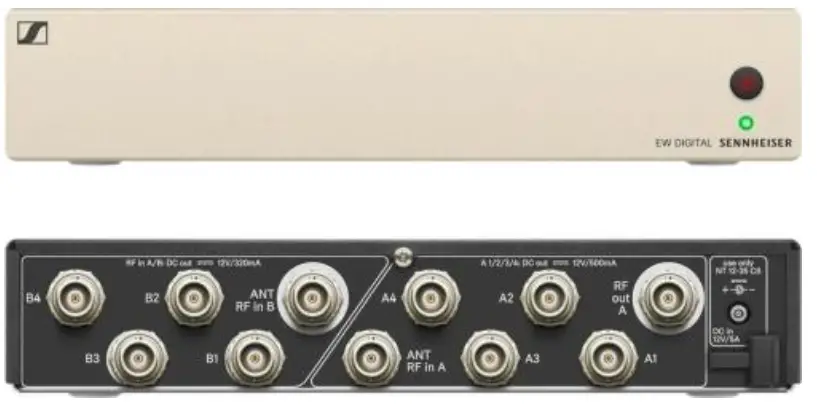
Product overview
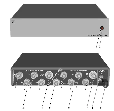
- STANDBY button
- See „Switching the EW-D ASA on and off“
- LED: Operation indicator
- See „Switching the EW-D ASA on and off“
- 4 BNC sockets B1 to B4
- RF outputs of diversity branch B for connection to the receiver
- See „Connecting receivers to the EW-D ASA“
- ANT RF IN B BNC socket
- Antenna input of diversity branch B
- See „Connecting antennas“
- ANT RF IN A BNC socket
- Antenna input of diversity branch A
- See „Connecting antennas“
- 4 BNC sockets A1 to A4
- RF outputs of diversity branch A for connection to the receiver
- Every one of these RF outputs can also provide voltage to a receiver.
- See „Connecting receivers to the EW-D ASA“
- RF OUT A BNC socket
- RF output only for connecting an additional ASA 214 to build an 8-channel diversity system
- See „Configuring multi-channel systems“
- DC in socket
- To connect the NT 12-35 CS power supply unit
- See „Connecting/disconnecting the EW-D ASA to/from the power supply system“
- Strain relief for the connection cable of the power supply unit
- See „Connecting/disconnecting the EW-D ASA to/from the power supply system“
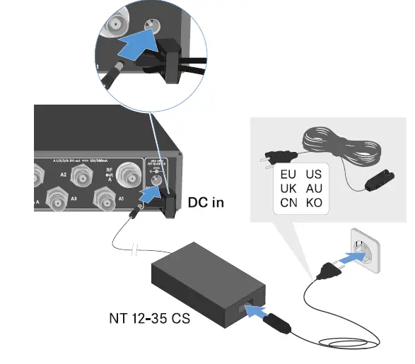
Connecting/disconnecting the EW-D ASA to/from the power supply system
To supply power to the EW-D ASA, the connected receivers and any antenna amplifiers used, you will need the NT 12-35 CS
power supply unit.
Use only the supplied NT 12-35 CS power supply unit. It is designed for your antenna splitter and ensures safe operation.
To connect the EW-D ASA antenna splitter to the power supply system:
- Plug the hollow jack plug of the power supply unit into the DC in socket of the antenna splitter.
- Pass the cable of the power supply unit through the strain relief.
- Connect one end of the power cord to the power supply unit and the other end to the wall socket.
To completely disconnect the EW-D ASA antenna splitter from the power supply system:
- Unplug the power cable from the wall socket.
- Unplug the hollow jack plug of the power supply unit from the DC in socket of the antenna splitter.
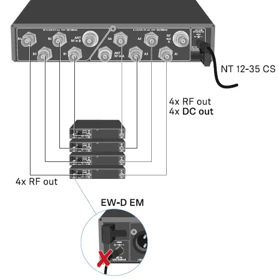
Connecting receivers to the EW-D ASA
You can connect and operate up to four EW-D EM rack receivers with the EW-D ASA.
To connect the receivers to the EW-D ASA antenna splitter:
- Connect one of the receiver’s antenna inputs to one of the BNC sockets A1 to A4 using one of the supplied BNC cables.
- The receivers do not require a separate power supply. They are powered via the BNC sockets A1 to A4.
- Connect the receiver’s other antenna input to one of the BNC sockets B1 to B4 using one of the supplied BNC cables.

Connecting antennas
To ensure optimal reception even in the case of poor reception conditions, we recommend using remote antennas.
Connecting remote antennas
- Mount two antennas or a combination of an antenna and an antenna amplifier to the BNC sockets ANT RF IN A and ANT RF IN B.
- Refer to the instructions under „Information on antenna amplifiers and cable lengths“.
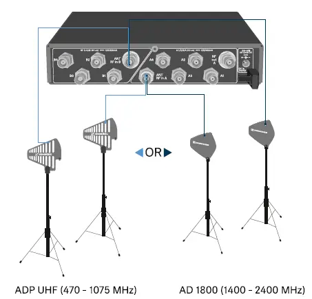
Connecting rod antennas
- Mount the antennas to the BNC sockets ANT RF IN A and ANT RF IN B.
- Align the antennas in a V-shape in order to ensure the best possible reception.
Information on antenna amplifiers and cable lengths
The following table shows which cable lengths require the use of the EW-D AB antenna amplifier as well as the maximum
recommended cable lengths.
Frequency variants of the EW-D AB: „EW-D AB antenna booster“
Configuring multi-channel systems
The following options for connecting multi-channel systems are possible:
Option 1: Two antennas supply a 4-channel system 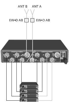
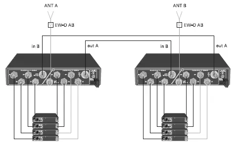
Option 2: Two 4-channel systems are interconnected
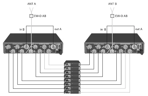
Option 3: Two antennas supply a 8-channel system
Installing the EW-D ASA in a rack
CAUTION
Rack mounting poses risks
When installing the device in a closed 19″ rack or multi-rack assembly, please consider that, during operation, the ambient temperature, the mechanical load and the electrical potentials will be different from those of devices which are not mounted into a rack. Make sure that the ambient temperature within the rack does not exceed the permissible temperature limit stated in the specifications. See „SPECIFICATIONS“.
- Ensure sufficient ventilation; if necessary, provide additional ventilation.
- Make sure that the mechanical load of the rack is even.
- When connecting to the power supply system, observe the information indicated on the type plate. Avoid overloading the
circuits. If necessary, provide overcurrent protection. - When mounting in a rack, please note that intrinsically harmless leakage currents of the individual power supply units may
accumulate, thereby exceeding the permissible limit value. As a remedy, ground the rack via an additional ground
connection.
To mount the antenna splitter in a rack, you will need the GA 3 rack mount kit (optional accessory). Rack mounting is carried out in the same way as for the EW-D EM receiver: „Installing receivers in a rack“.
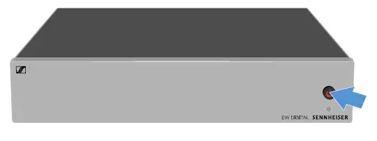
Switching the EW-D ASA on and off
To switch on the antenna splitter:
Short-press the STANDBY button.
The antenna splitter switches on and the power LED turns green.
- The RF signals of the connected antennas are distributed to all connected receivers.
To switch the antenna splitter to standby mode:
- Press the STANDBY button for approx. 2 seconds.
The LED turns off. The connected antenna amplifiers are switched off. Connected receivers are switched off if they draw their supply voltage from the BNC sockets A1 to A4 (see „Connecting receivers to the EW-D ASA“).
- To fully switch off the antenna splitter:
Disconnect the antenna splitter from the power supply system by unplugging the power supply unit from the wall socket.
The LED turns off.


