![]()
![]() S600 Laser Scanner
S600 Laser Scanner
User Guide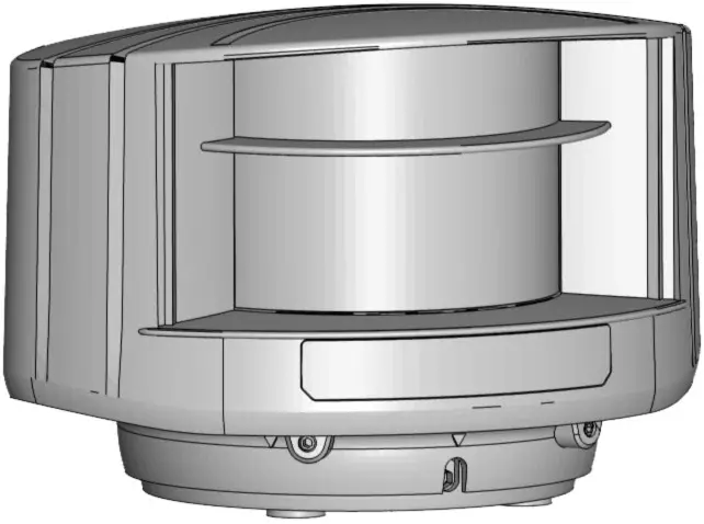
LZR® -S600
LASER SCANNER FOR BUILDING AUTOMATION & SECURITY with max. detection range of 82 ft x 82 ft
75.5792.08 LZR-S600 20220429
Visit the website for the available languages of this document.

READ BEFORE BEGINNING INSTALLATION/PROGRAMMING/SET-UP
SAFETY
CLASS 1 LASER PRODUCT
CLASS 2 LASER RADIATION
DURING INSTALLATION
DO NOT STARE INTO THE BEAM
IEC 60825-1
The device emits invisible (IR) and visible laser radiation.
IR laser: wavelength 905nm; output power 0.10mW (Class 1 according to IEC 60825-1)
Visible laser: wavelength 635nm; output power 0.95mW (Class 2 according to IEC 60825-1)
The visible laser beams are inactive during normal operation.
The installer can activate the visible lasers if needed.
Do not stare into visible laser beams.![]() CAUTION!
CAUTION!
Use of controls, adjustments, or performance of procedures other than those specified herein may result in hazardous radiation exposure.
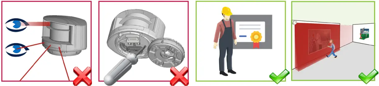 | |||
| Do not look into the laser emitter or the visible red laser beams. | The warranty is void if unauthorized repairs are made or attempted by unauthorized personnel. | Only trained and qualified personnel are recommended to install and set up the sensor. | Test the proper operation of the installation before leaving the premises. |
INSTALLATION AND MAINTENANCE
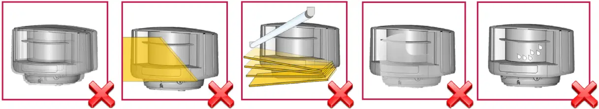 | ||||
| Avoid extreme vibrations. | Do not cover the laser windows. | Avoid moving objects and light sources in front of the laser window. | Avoid the presence of smoke and fog in the detection field. | Avoid condensation on the laser windows. |
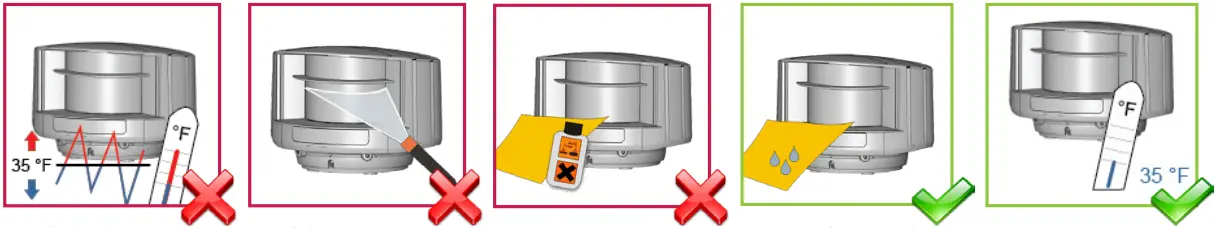 | ||||
| Avoid exposure to sudden and extreme temperature changes. | Avoid direct exposure to high-pressure cleaning. | Do not use aggressive products to clean the laser windows. | Clean the laser window with compressed air. If needed, wipe only with a soft, clean, and damp microfibre cloth. | Keep the sensor permanently powered in environments where the temperature can drop below 35 °F. |
DESCRIPTION
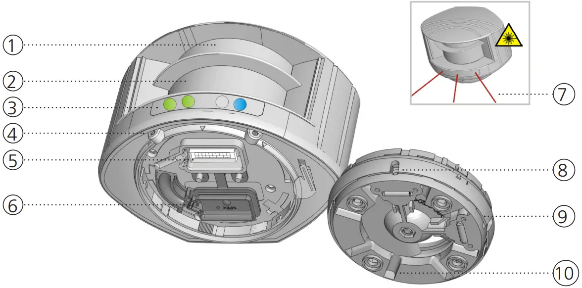
| 1. laser window – emission 2. laser window – reception 3. LED signals (4) 4. screws for position lock (2) 5. connector | 6. protection cover 7. visible laser beams (3) 8. notches for tilt angle adjustment (2) 9. adjustable bracket 10. cable conduits (4) |
LED SIGNAL
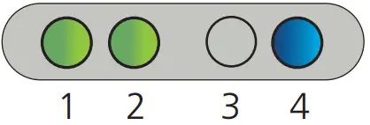
- Detection LED: R1 – opening field
- Detection LED: R2 – safety field
- Error LED
- Power LED
| DETECTION LEDs | ERROR LED | POWER LED | |||
| detection (red) | error (orange) | power (blue) | |||
| no detection (green) | no error (off) | no power (on) | |||
| LED flashes quickly | LED flashes | ||
| LED flashes slowly | LED is off |
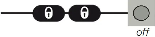
 | All 4 LEDs can be switched off and on again by remote control. This can be useful in cases where the sensor should not draw any attention. | 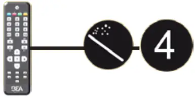 |
SYMBOLS
 |  | ||
| Caution! Laser radiation | Remote control sequence | Possible remote control adjustments | Factory values |
| |||
| Alarm | Tip | Quick installation | |
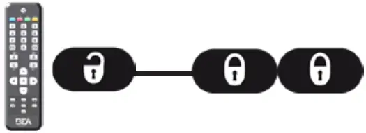
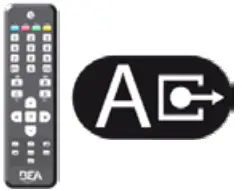
HOW TO USE THE REMOTE CONTROL
 |  |  |
| After unlocking, the red LED flashes and the sensor can be adjusted by remote control. | If the red LED flashes quickly after unlocking, you need to enter an access code from 1 to 4 digits. | To end an adjustment session, always lock the sensor. |
ADJUSTING ONE OR MORE PARAMETERS
CHECKING A VALUE
RESTORING TO FACTORY VALUES 
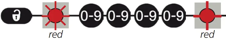
SAVING AN ACCESS CODE
The access code is recommended for sensors installed close to each other. 
DELETING AN ACCESS CODE

 | 30 minutes after last use, the sensor locks access to the remote control session. To regain access, cycle the power. The remote control session will then be accessible for another 30 minutes. |
POSSIBLE APPLICATIONS
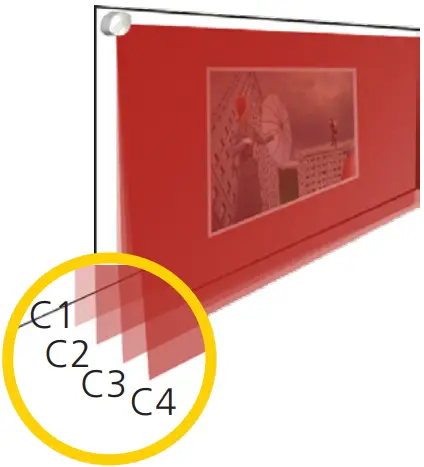
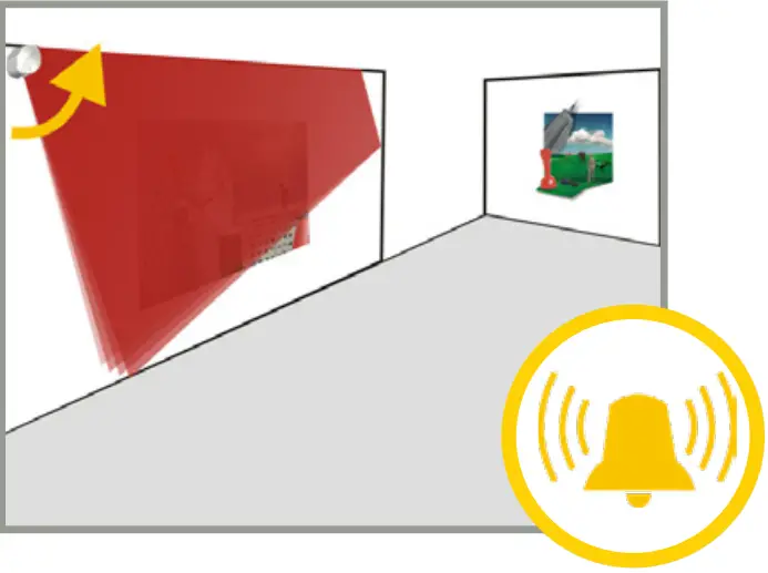
PROTECTION OF WORKS OF ART: WARNING & ALARM
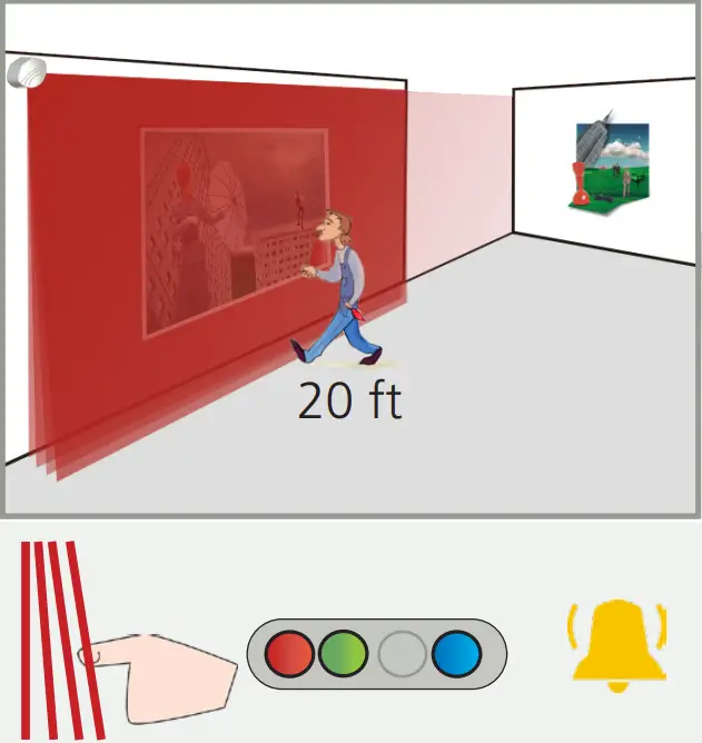 Field 1 (4 active curtains) triggers relay 1:
WARNING
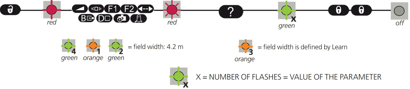
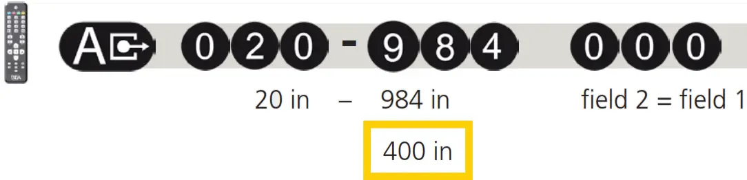
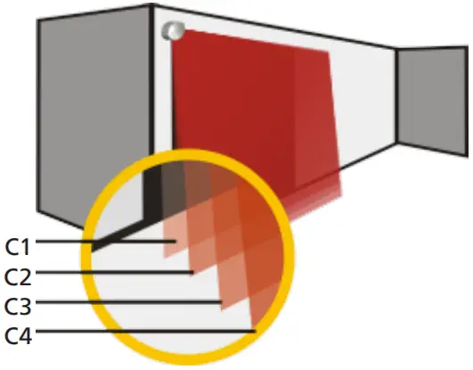
Adapt the field widths (ex: 20 ft):
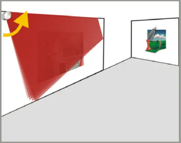
Reduce field 2 to one curtain (C1):
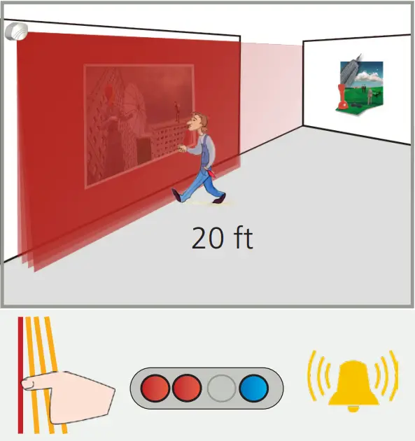 Field 2 (only curtain C1 active) triggers relay 2:
ALARM 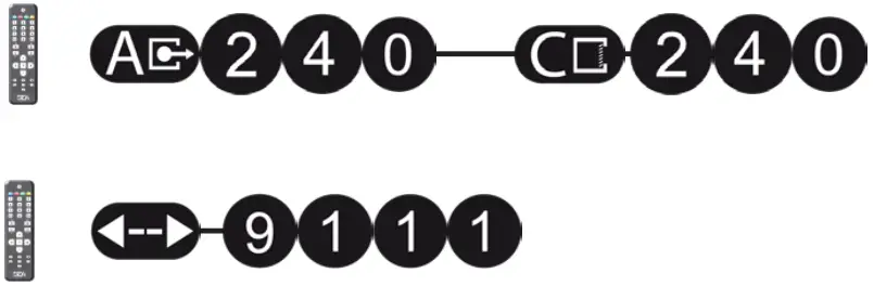
DAY AND NIGHT FEATURE
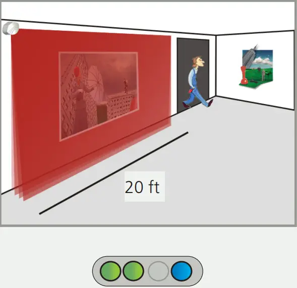 During the daytime, only field 1 is active and triggers relay 1.
Adapt the field width of field 1 (ex: 20 ft):
Adapt the field width of field 2 (ex: 25 ft):
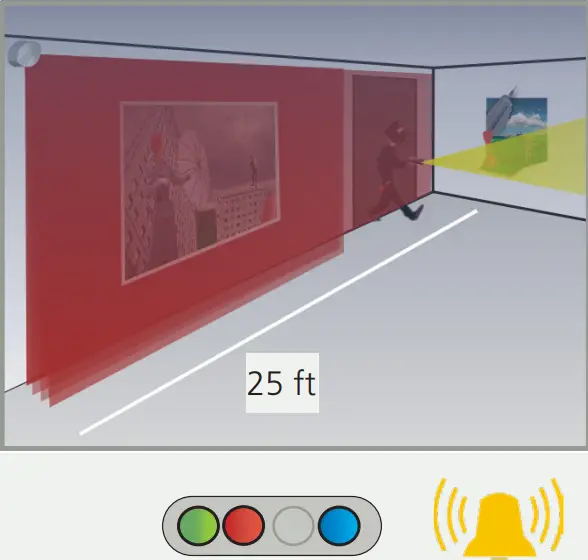 During the nighttime, field 2 is active as well and triggers relay 2 (intrusion alarm).
- MOUNTING

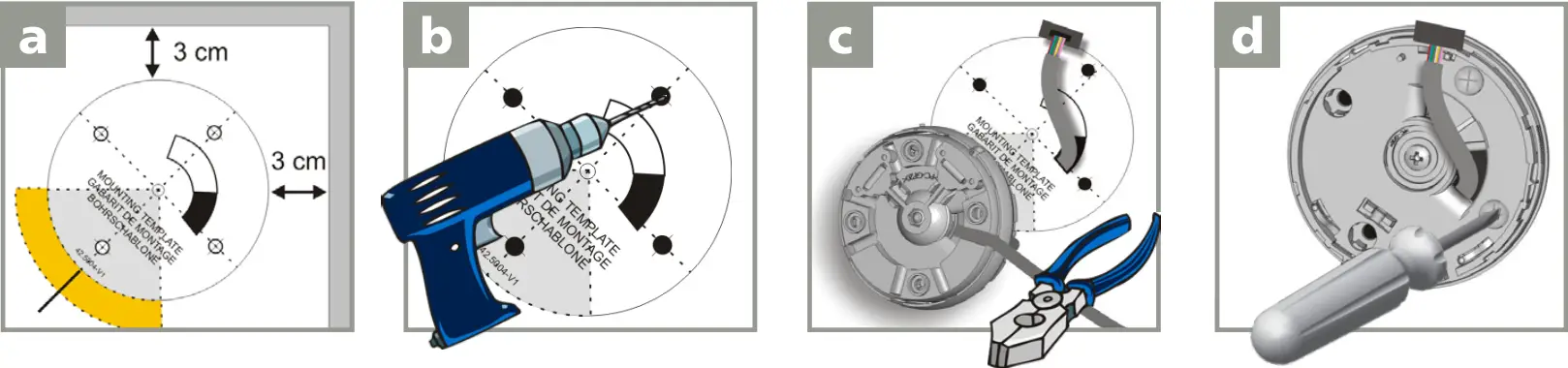
Use the mounting template to position the sensor correctly.
The gray area indicates the detection range.Drill 4 holes as indicated on the mounting template.
Drill a hole (1/2 inch min.) for the cable if possible.Pass the cable ±4 inches through the cable opening.
If drilling an opening is not possible, use the cable conduits on the back side
of the bracket.Position the bracket and secure using the 4 screws to avoid vibrations. 
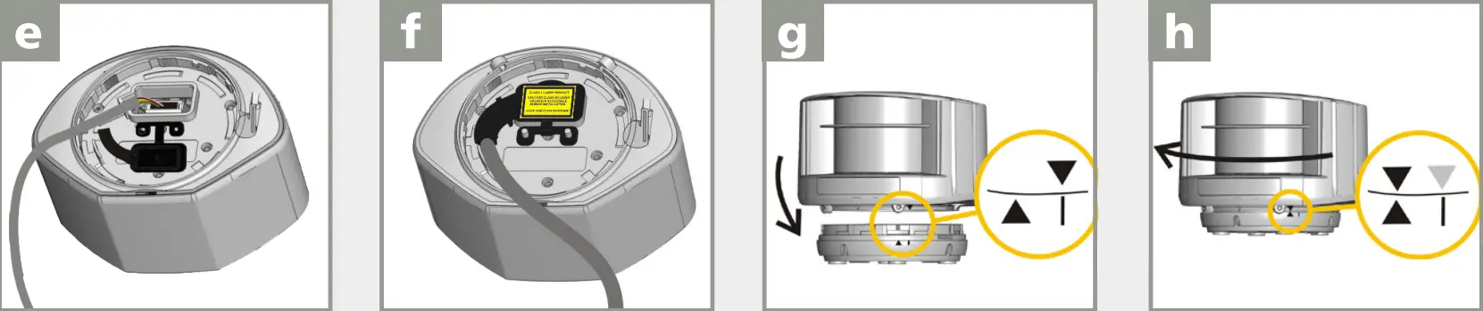
Open the protection cover, plug the
connector, and position the cable in the slit.Close and secure the protection cover.
NOTE: FACTORY WARRANTY VOIDED IF PROTECTION COVER IS NOT USED!Position the housing on the bracket. Rotate the sensor until the two triangles are face to face. - WIRING
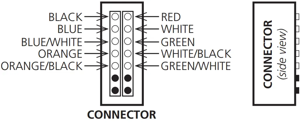
Use the visual aid below to ensure the correct wiring to the door control.Red (+)
Black (-)
Power supply (10 – 35 VDC) White
Green
Relay 1: Opening Field White/Black
Green/White
Relay 2: Safety Field Blue (+)
Blue/White (-)
Test Orange
Orange/Black
Learn To launch a Learn, apply power for the length of time in which the Learn is to be performed (minimum of 1 millisecond).
 No test function:
connect blue and blue/white wires to the power supply (no polarity) No, Learn via input:
connect orange and orange/black wires to the ground/common - POSITIONING

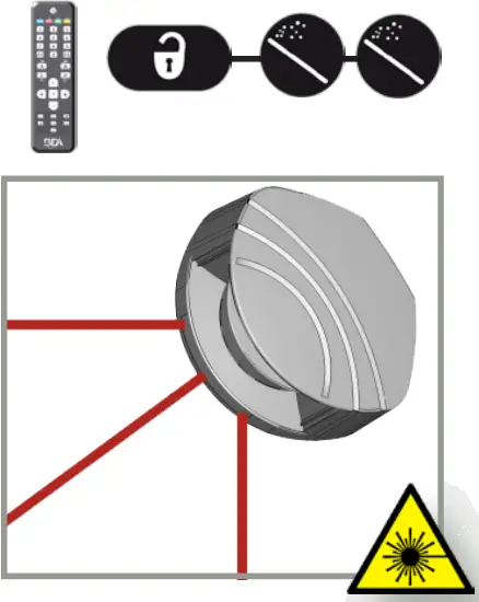
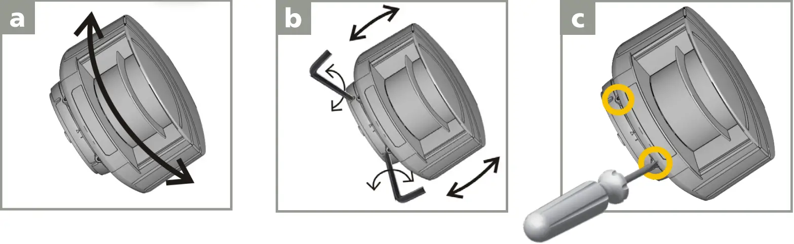
Unlock the sensor and activate the visible laser beams.
The visible laser beams indicate the approximate position of curtain C1 and the angle of the detection field.
The visible laser beams will remain active for 15 minutes or can be turned off the same way they were activated.

Adjust the lateral position of the detection field. Adjust the tilt angle of the detection field with the 3 mm hex key. Lock the position of the mounting bracket to avoid malfunctioning in case of extreme vibrations. - MOUNTING SIDE
Select the corresponding mounting side.
The sensor learns its environment and automatically determines the detection field(s). Both red LEDs flash slowly and the 3 visible laser beams automatically light up for 30 seconds.Stay outside of the detection field to avoid disturbances.
WITH BACKGROUND WITHOUT BACKGROUND 

The sensor memorizes the floor as a reference point and signals a fault when its orientation is changed (observe the orange flashing LED). No reference point is memorized.
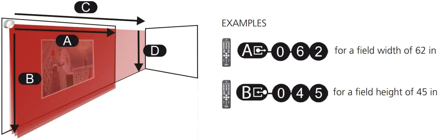
No alarm in case of interference. - FIELD DIMENSIONS
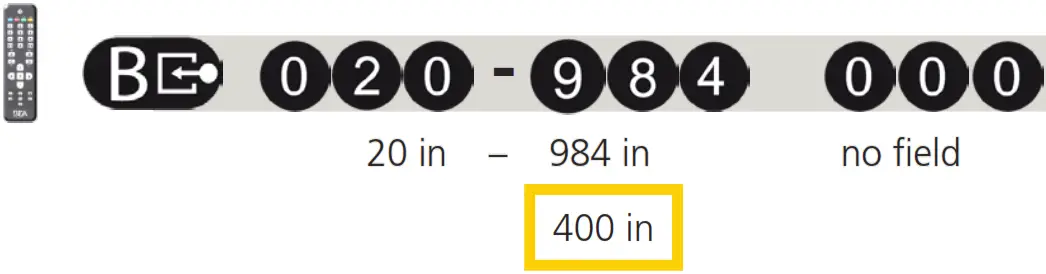
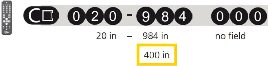
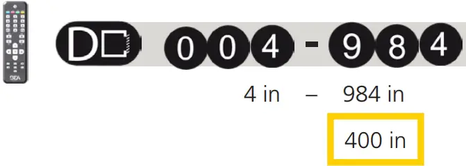
FIELD 1 WIDTH 
HEIGHT 
FIELD 2 WIDTH 
HEIGHT 
 IMPORTANT: Test the proper operation of the installation before leaving the premises.

 IMPORTANT: Test the proper operation of the installation before leaving the premises.
LEARN
The Learn can be launched either via remote control or by connecting the orange and orange/black wires.
Launch a Learn under the following conditions: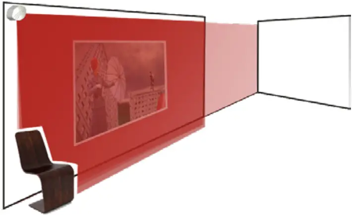
- after changing the sensor position
- when new objects are added to or changed in the detection zone
During Learn, the sensor learns its surroundings and adapts the detection zone shape. Objects in the detection field will be cut out.![]() Stay outside of the detection field to avoid disturbances.
Stay outside of the detection field to avoid disturbances.
To launch a Learn via remote control, use the following sequence: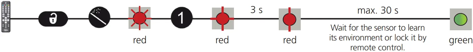
REMOTE CONTROL ADJUSTMENTS (OPTIONAL)
ACTIVE DETECTION CURTAINS
 | ||||
| CURTAIN | C1 | C2 | C3 | C4 |
- deactivate curtain on both fields
- activate curtain only on field 1
- activate curtain only on field 2
- activate curtain on both fields
Ex:
 |  |  |
| C1 + C2 are active in the safety field C3 + C4 are active on an optional field | C1 is active in both fields C2+C3 are active in the safety field C4 is inactive | All curtains are active on both fields |
The distances between the curtains depending on the mounting height and location. When mounted on the left, the distance between curtain C1 and curtain C4 is approximately 0.3 ft for every foot (mounting height).
Example: At 10 feet, the distance between C1 and C4 is 1.5 feet.
| UNCOVERED ZONE |  |
| IMMUNITY FILTER | 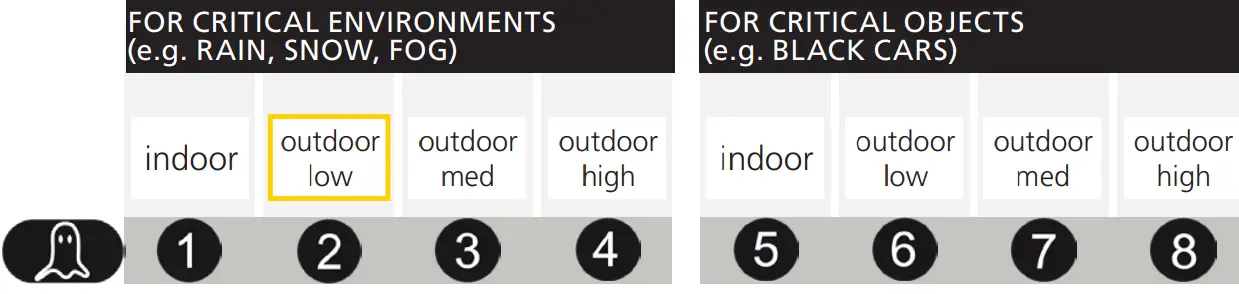 |
| MIN. OBJECT SIZE (approximate values) |  |
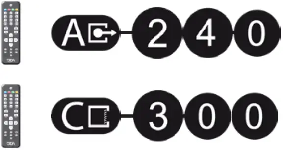
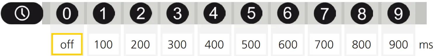
| OUTPUT ACTIVATION DELAY (approximate values) | The outputs are triggered after a constant detection time of x ms. (ex: value 3 = 300 ms)
|
| DETECTION FIELD REDIRECTION R = relay output | 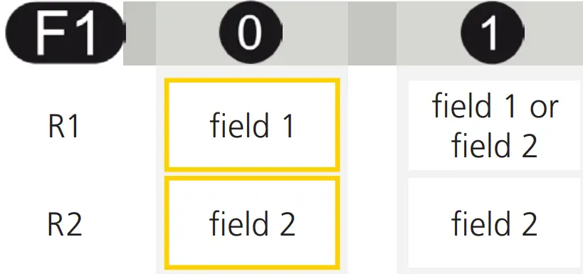 |
OUTPUT CONFIGURATION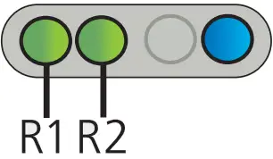 R = relay output | 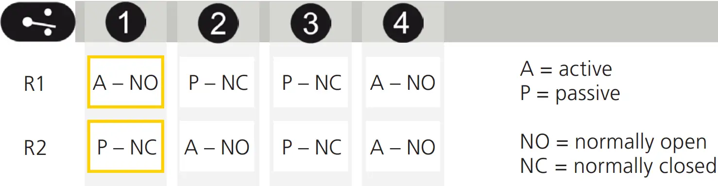 |
TROUBLESHOOTING
| No blue LED | No power | Check cable and connection. | |
| The polarity of the power supply is inverted | Check the polarity of the power supply. | ||
| All LEDs have been deactivated by remote control | Activate LEDs using the remote control. | ||
| Only blue LED is on | Test input is not connected | Check to wire. The blue and blue/white cable must be connected to the test input or the power supply. | |
| Detection LED remains green | Detection field too small or deactivated | Check the size of fields. | |
| Launch a Learn. | |||
| The object size is too small | Decrease minimum object size. | ||
| Detection LED remains red | Someone/Something is in the detection field | Step out of the field and/or remove the any object(s) from the field. | |
| The field is touching floor/wall/door – this leads to detection | Activate the 3 red beams and check if the position of the sensor is correct. If not, adjust the hex screws. | ||
| Verify the field size. | |||
| Launch a Learn. | |||
| Orange LED flashing and detection LEDs are red | No background (reference point) is found | Check the position of the sensor. | |
| Check the mounting side setting. If no reference point is found, set the mounting side to value 3 to 5. | |||
| Launch a new Learn. | |||
| Sensor is masked | Verify and clean the front screens with a damp cloth. | ||
| Orange LED is on Both detection LEDs are orange | Power supply voltage exceeds acceptable limits | Check power supply voltage. | |
| Sensor exceeds temperature limits | Verify the temperature of the environment. Protect the sensor from sunlight using a cover, if necessary. | ||
| Internal error | Wait a few seconds. If the LED remains ON, reset the power supply. If the LED turns on again, replace the sensor. | ||
| The sensor does not respond to the remote control | 30 minutes after last use, the sensor locks access to RC | Cut and restore power supply. RC is accessible again for 30 minutes. | |
| Remote control batteries not installed properly or are dead | Check battery orientation or replace the batteries. | ||
| The remote control is not pointed correctly | Point the remote control towards the sensor, but with a slight angle. The RC should not be pointed at a right angle in front of the sensor. | ||
| The reflective object is close to the sensor | Avoid highly reflective material in proximity to the sensor. | ||
 | The sensor does not unlock | Access code needs to be entered or an incorrect code was used | Cut and restore power supply. No code is required to unlock during the first minute after powering. |
Can’t find your answer?
Visit www.beainc.com or scan the QR code for Frequently Asked Questions!

TECHNICAL SPECIFICATIONS
| Technology: | LASER scanner, Time-of-Flight measurement | |||
| Detection mode: | motion and presence | |||
| Detection range: | Default: 33’ x 33’ @ 2% remission factor (max. 82 ft x 82 ft) | |||
| Angular resolution: | 0.3516° | |||
| Min. detected object size (Typ.): | 0.8 in @ 10 ft 1.4 in @ 16 ft 2.8 in @ 33 ft 6.9 in @ 82 ft | |||
| Emission characteristics of IR laser: Red visible laser: | wavelength 905 nm; output power 0.10mW (CLASS 1) wavelength 635 nm; output power 0.95mW (CLASS 2) | |||
| Supply voltage: | 10 – 35 VDC @ sensor side | |||
| Power consumption: | < 5 W | |||
| Peak current @ power-on: | 1.8 A (max. 80 ms @ 35 V) | |||
| Cable length: | 33’ | |||
| Response time: | Typ. 20 ms (max. 80 ms) + output activation delay | |||
| Output: Max. switching voltage: Max. switching current: Switching time: Output resistance: Voltage drop on output: Leakage current: | 2 electronic relays (galvanic-isolated – polarity-free) 35 VDC / 24 VAC 80 mA (resistive) tON = 5 ms; tOFF = 5 ms type 30 Ω < 0.7 V @ 20 mA < 10 µA | |||
| Input: Max. contact voltage: Voltage threshold: | 2 optocouplers (galvanic-isolated – polarity-free) 30 VDC (over-voltage protected) Log. Active High: > 8 VDC Log. Active Low: < 3 VDC | |||
| Response time monitoring input: | < 5 ms | |||
| LED signal: | 1 blue LED: power-on status 1 orange LED: error status 2 bi-colored LEDs: detection/output status (green = no detection, red = detection) | |||
| Dimensions: | 3 5⁄8”× 2 3⁄4”× 5” (W × H × D) mounting bracket: + 1⁄2” | |||
| Material: | PC/ASA | |||
| Color: | Black | |||
| Mounting angles on bracket: | -45°, 0°, 45° | |||
| Rotation angles on bracket: | -5 – 5° (lockable) | |||
| Tilt angles on bracket: | -3 – 3° | |||
| Protection degree: | NEMA 4 / IP65 | |||
| Temperature range: | powered: -22 – 140 °F (-30 – 60 ºC) | unpowered: 14 – 140 °F (-10 – 60 ºC) | ||
| Humidity: | 0 – 95% non-condensing | |||
| Vibrations: | < 2G | |||
| Pollution on front screen: | max. 30%, homogenous | |||
| Norm conformity: | 2006/95/EC: LVD 2002/95/EC: RoHS | 2004/108/EC: EMC IEC 60529: 2001 | IEC 60825-1: 2007 IEC 60950-1: 2005 | IEC 61000-6-2: 2005 IEC 61000-6-3: 2006 |
Specifications are subject to change without prior notice. All values are measured in specific conditions.
BEA, INC. INSTALLATION/SERVICE COMPLIANCE EXPECTATIONS
BEA, Inc., the sensor manufacturer, cannot be held responsible for incorrect installations or incorrect adjustments of the sensor/device; therefore, BEA, Inc. does not guarantee any use of the sensor/device outside of its intended purpose.
BEA, Inc. strongly recommends that installation and service technicians be AAADM-certified for pedestrian doors, IDA-certified for doors/gates, and factory-trained for the type of door/gate system.
Installers and service personnel are responsible for executing a risk assessment following each installation/service performed, ensuring that the sensor/device system performance is compliant with local, national, and international regulations, codes, and standards.
Once installation or service work is complete, a safety inspection of the door/gate shall be performed per the door/gate manufacturer’s recommendations and/or per AAADM/ANSI/DASMA guidelines (where applicable) for best industry practices. Safety inspections must be performed during each service call – examples of these safety inspections can be found on an AAADM safety information label (e.g. ANSI/DASMA 102, ANSI/DASMA 107, UL294, UL325, and International Building Code).
Verify that all appropriate industry signage, warning labels, and placards are in place.![]()
©BEA | Original Instructions | PLEASE KEEP FOR FURTHER USE – DESIGNED FOR COLOR PRINTING
![]() Tech Support & Customer Service: 1-800-523-2462
Tech Support & Customer Service: 1-800-523-2462
General Tech Questions: [email protected]
Tech Docs: www.BEAsensors.com
75.5792.08 LZR-S600 20220429


