![]() 75.5984.04 LZR-H100 20220105
75.5984.04 LZR-H100 20220105
![]()
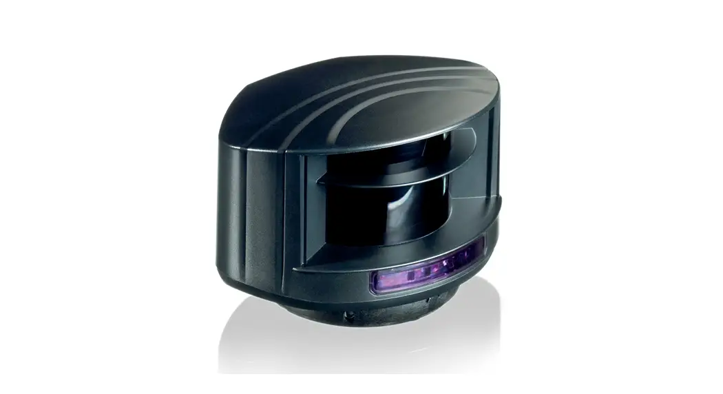
LZR® -H100
LASER SCANNER FOR BARRIERS & GATES
with max. detection range of 32’ × 32’
User’s Guide
Visit website for
available languages of
this document. http://esp.to/wCzIKi
READ BEFORE BEGINNING INSTALLATION/PROGRAMMING/SET-UP
SAFETY
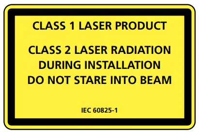
The device emits invisible (IR) and visible laser radiation.
IR laser: wavelength 905nm; output power 0.10mW (Class 1 according to IEC 60825-1)
Visible laser: wavelength 635nm; output power 0.95mW
(Class 2 according to IEC 60825-1)
The visible laser beams are inactive during normal operation.
The installer can activate the visible lasers if needed.
Do not stare into visible laser beams.
![]() CAUTION!
CAUTION!
Use of controls, adjustments, or performance of procedures other than those specified herein may result in hazardous radiation exposure.
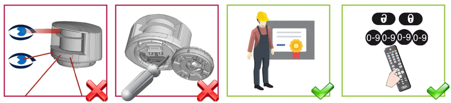 | |||
| Do not look into the laser emitter or the visible red laser beams. | The warranty is void if unauthorized repairs are made or attempted by unauthorized personnel. | Only trained and qualified personnel are recommended to install and set up the sensor. | After installation, enter an access code by remote control. |
This sensor is designed to be used as a movement and presence sensor to control the opening and the closing process of a gate or a barrier. The installer of the system is responsible for installing the sensor and the system in compliance with applicable national and international standards on safety. The manufacturer of the sensor cannot be held responsible for incorrect installations or inappropriate adjustments of the sensor.
This device is not intended for use in with any automatically activated doors. US Pat. No. 7,084,388, which is not owned by BEA, covers automatic doors comprising, among other things, a scanning detector. The LZR-H100 is not sold with consent, implied or otherwise, for use with automatically activated doors, as set forth in the aforementioned patent.
INSTALLATION AND MAINTENANCE
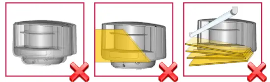 | ||
| Avoid extreme vibrations. | Do not cover the laser windows. | Avoid moving objects and light sources in front of the laser window. |
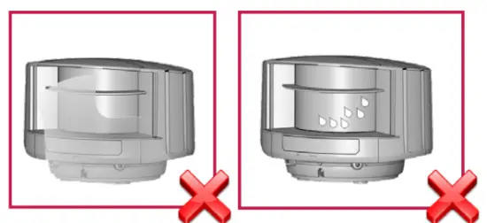 | ||
| Avoid the presence of smoke and fog in the detection field. | Avoid condensation on the laser windows. | |
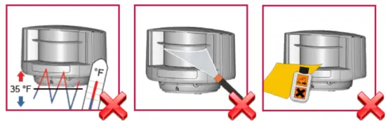 | ||
| Avoid exposure to sudden and extreme temperature changes. | Avoid direct exposure to high-pressure cleaning. | Do not use aggressive products to clean the laser windows. |
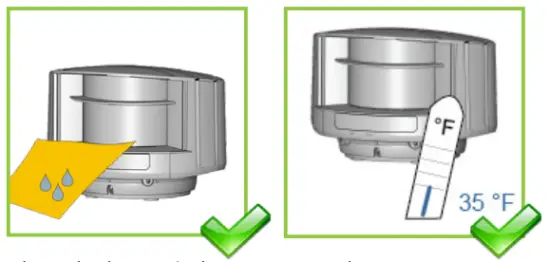 | ||
| Clean the laser window with compressed air. If needed, wipe only with a soft, clean, and damp microfibre cloth. | Keep the sensor permanently powered in environments where the temperature can drop below 35 °F. | |
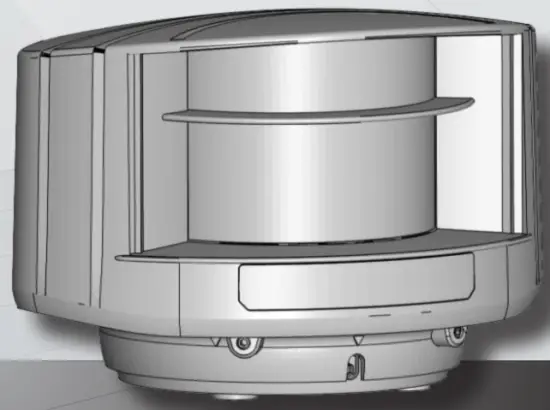
DESCRIPTION
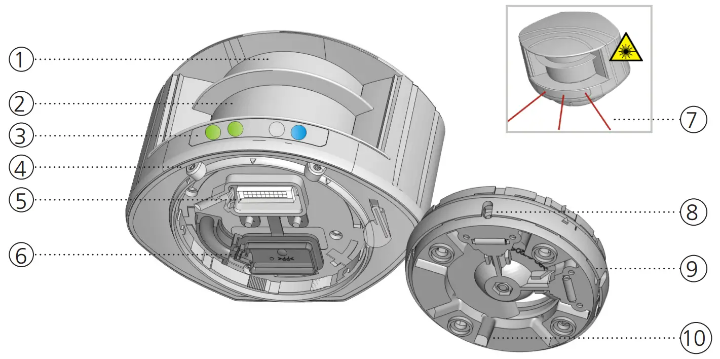
- laser window – emission
- laser window – reception
- LED signals (4)
- screws for position lock (2)
- connector
- protection cover
- visible laser beams (3)
- notches for tilt angle adjustment (2)
- adjustable bracket
- cable conduits (4)
LED SIGNAL
![]()
- Detection LED: R1 – opening field
- Detection LED: R2 – safety field
- Error LED
- Power LED
| DETECTION LEDs | ERROR LED | POWER LED | |||
| detection (red) | error (orange) | power (blue) | |||
| no detection (green) | no error (off) | no power (on) | |||
| LED flashes quickly | |
| LED flashes | |
| LED flashes slowly | |
| LED is off |
![]() All 4 LEDs can be switched off and on again by remote control.
All 4 LEDs can be switched off and on again by remote control.
This can be useful in cases where the sensor should not draw any attention.
![]()
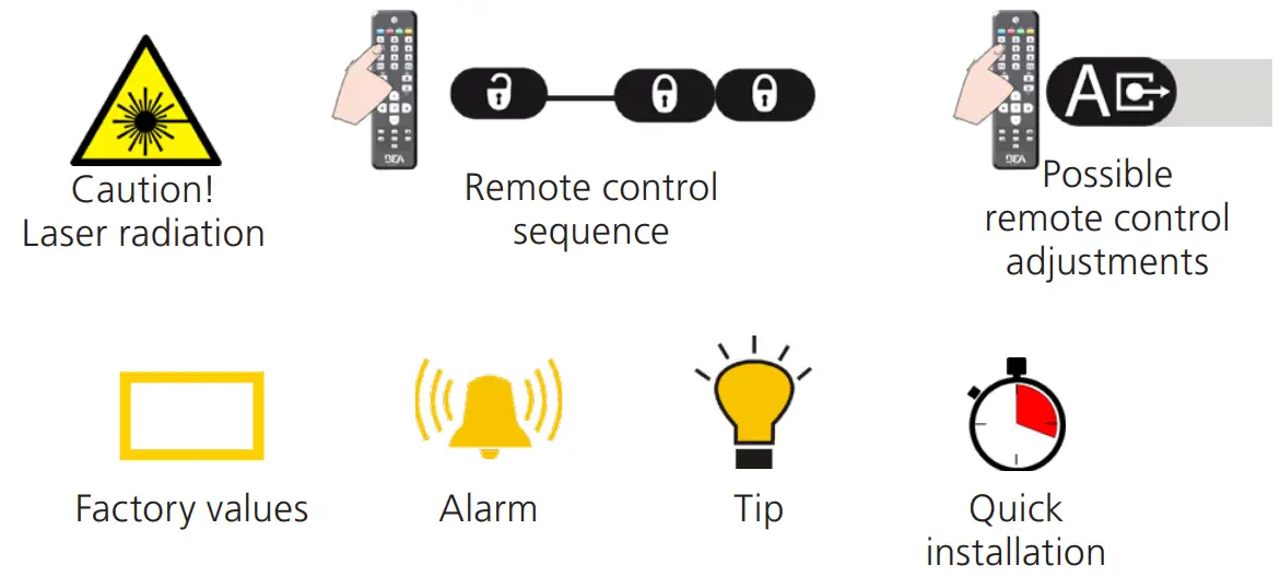
SYMBOLS
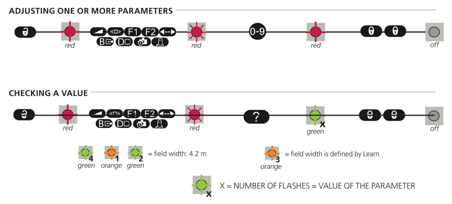
HOW TO USE THE REMOTE CONTROL
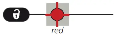 | 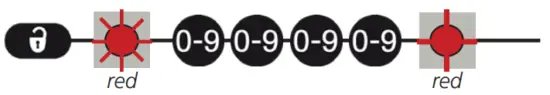 |  |
| After unlocking, the red LED flashes and the sensor can be adjusted by remote control. | If the red LED flashes quickly after unlocking, you need to enter an access code from 1 to 4 digits. | To end an adjustment session, always lock the sensor. |
![]() 30 minutes after last use, the sensor locks access to the remote control session. To regain access, cycle the power. The remote control session will then be accessible for another 30 minutes.
30 minutes after last use, the sensor locks access to the remote control session. To regain access, cycle the power. The remote control session will then be accessible for another 30 minutes.![]()
BASIC SETUP FEATURES
It is important to understand the basic setup features before installing the sensor.
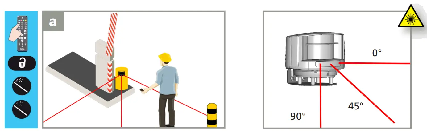
VISIBLE RED LASER BEAMS
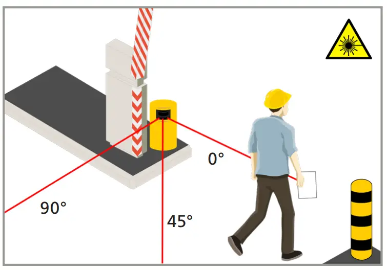
The sensor and detection field position are very important for the safe operation of the barrier.
In order to position the sensor correctly, use the 3 visible red laser beams.
![]()
The visible laser beams are also used to determine the location of the reference of the sensor.
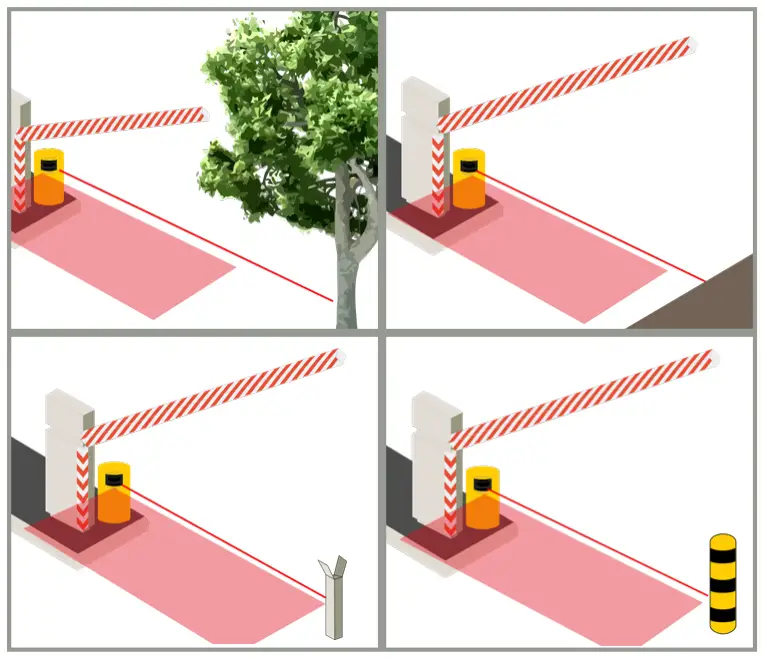
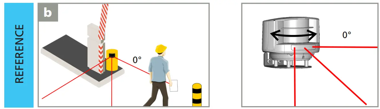
REFERENCE
The sensor must learn a reference when the safety field is the only protection against contact between the vehicle and the boom.
The reference can be adjusted on any type of object already present on-site (wall, tree, barrier boom support) or on a post.
Always make sure the object on which the reference is adjusted:
- is positioned in the continuity of the 0° laser beam
- is positioned in. at the end of the barrier or farther away than the end of the barrier
- has a surface of at least 6 inches
- is firmly fixed to the floor and not subject to vibrations
FOR BEST RESULTS:
- use the reflective sticker
- place the sticker horizontally on a cylindrical surface of the structure (as shown)
- center the laser’s red spot on the reflector
Use a reflective sticker (supplied) when the distance between sensor and reference is higher than 16.5 feet.
SAFETY FIELD
If the safety field is the only protection against contact with the barrier, the safety field of the sensor must be situated directly below the barrier.
This is only possible when the sensor is positioned correctly and the reference has been learned. If the reference is situated at the end of the barrier, the detection field width is the same as the reference distance.
If the reference is farther away, adjust the detection field width to the width of the barrier.
In order to maximize safety for mixed traffic (vehicles and trucks), an additional vertical detection zone is recommended (LZR-I30).
APPLICATION REQUIREMENTS
These requirements ensure optimal safety of the barrier in order to protect against contact with the barrier.
DOUBLE ACCESS LANE
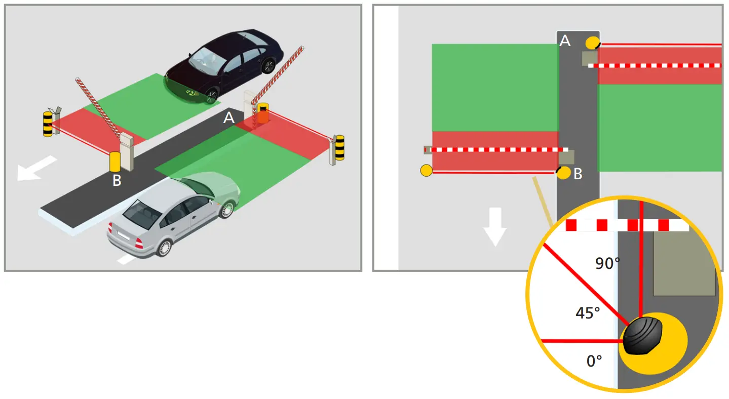
- 2 LZR-H100
- 2 references, 1 for each sensor
SINGLE ACCESS LANE
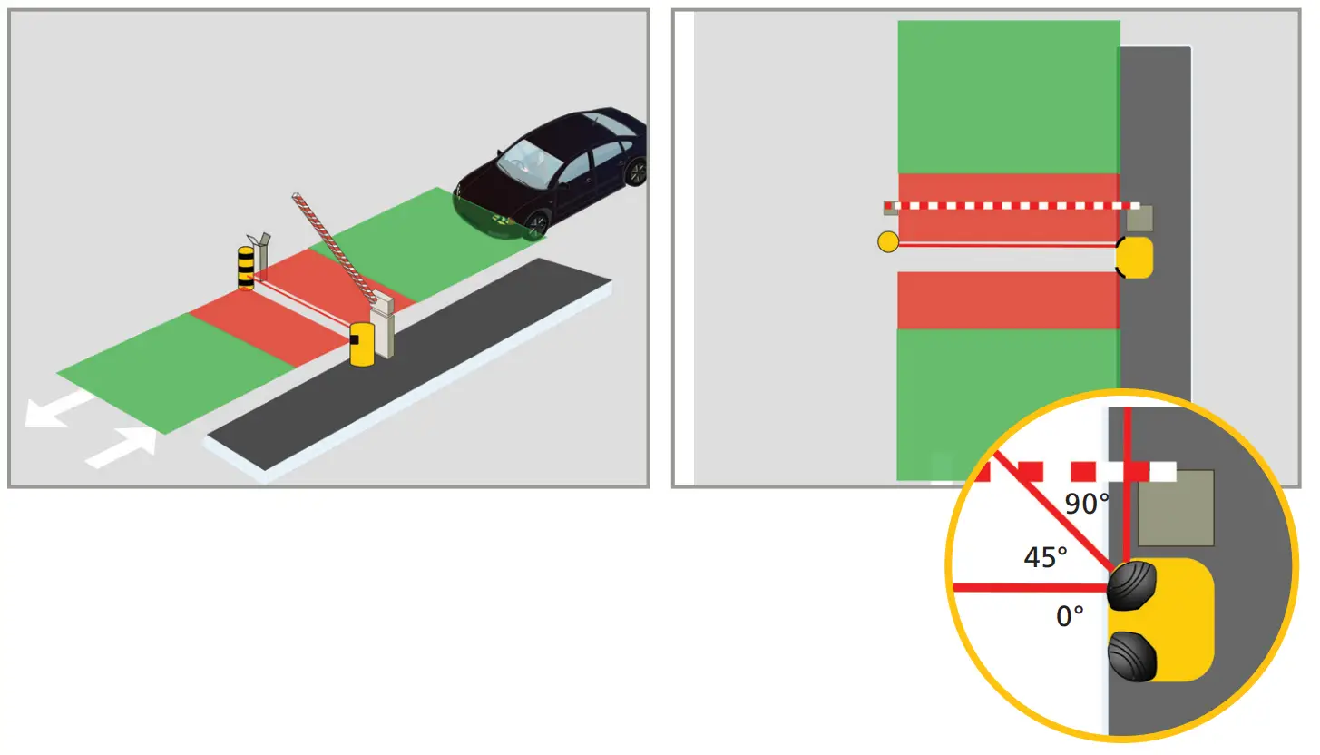
- 2 LZR-H100
- 1 reference
 SAFETY FIELD
 OPENING FIELD
RECOMMENDED MOUNTING
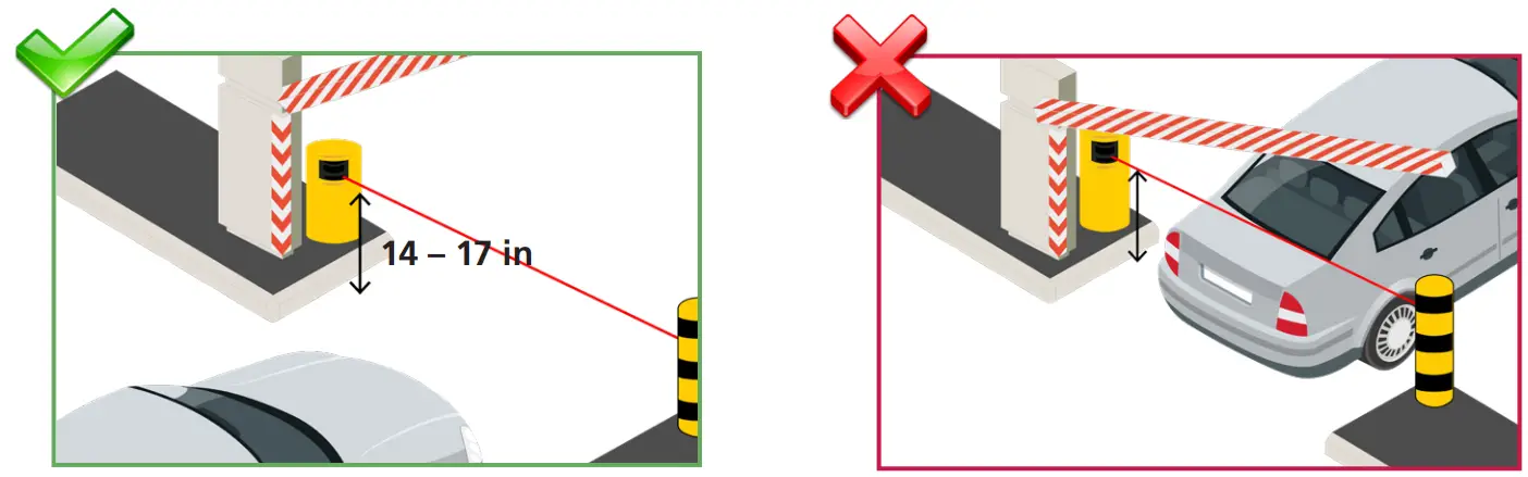 | |
| Install the sensor at a mounting height between 14 – 17 inches. If the barrier is only used by trucks, the mounting height may be increased. | If the 0º reference beam is too low or too high, vehicle contact with the barrier may occur. |
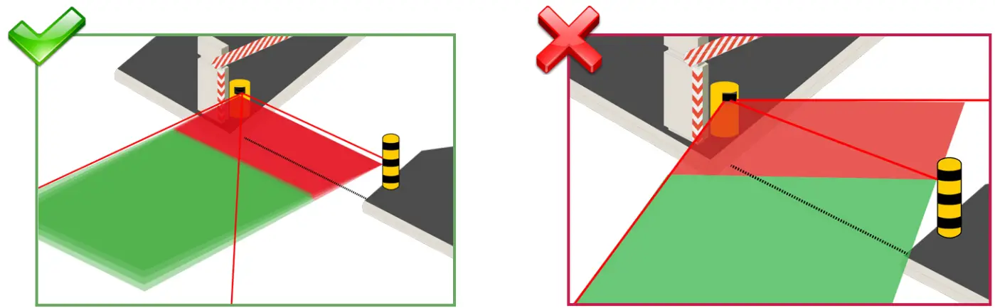 | |
| Ensure that the detection field is parallel to the barrier. | Do not position the detection field as shown. |
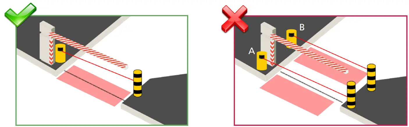 | |
| When using the safety field, place the sensor just behind the barrier to ensure that the safety field protects the area around the barrier. | When using the safety, do not place the sensor before the barrier (A) or more than 15 inches after the barrier (B). The area around the barrier is not safe. |
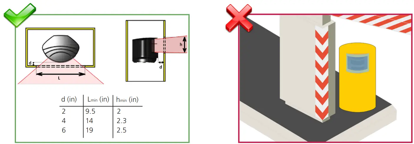 | |
| Ensure there are no obstructions in front of the sensor! | Do not cover the front face of the sensor with glass or plastic. |
MOUNTING
![]() Carefully read the application requirements and tips before mounting the sensor.
Carefully read the application requirements and tips before mounting the sensor.
The mounting position of the sensor is crucial for the safe operation of the barrier.
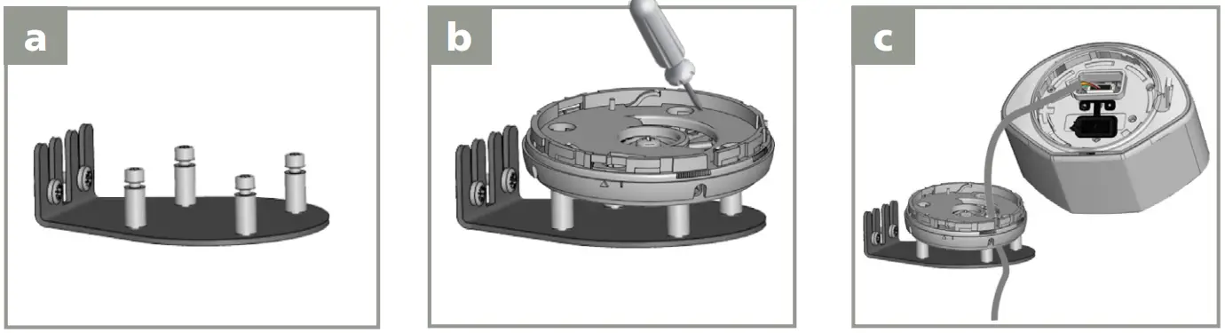 | ||
| Use a mounting post or a mounting accessory (e.g. LBA accessory) to secure the sensor to the pole. | Position the bracket and secure using the 4 screws to avoid vibrations. | Open the protection cover, plug the connector and position the cable in the raceway. |
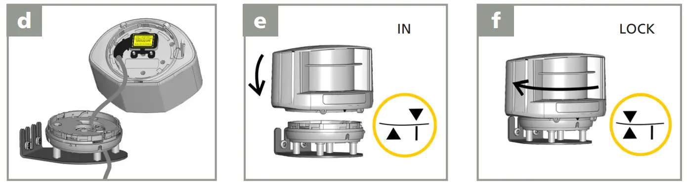 | ||
| Firmly close the protection cover. Do not pinch the cable. | Position the housing on the bracket. | Turn the sensor until the two triangles are aligned. |
WIRING
Use the visual aid below to ensure the correct wiring to the door control.
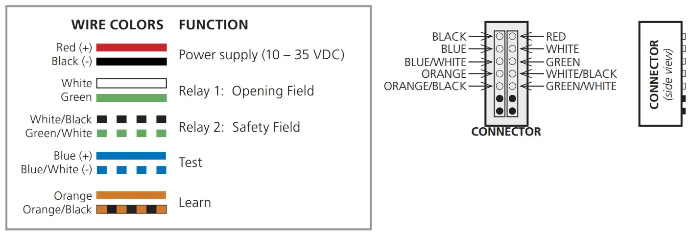
![]() No test function:
No test function:
Connect BLUE (DC+) and BLUE/WHITE (DC-) to the power supply. (no polarity)
| The LED signal at power-on: Correct positioning is needed | |
| Power on without test signal: Connect blue/white and blue wires to test or power supply. | |
| No detection | |
| Safety and opening detection | |
FIELD POSITIONING
![]() The detection field and reference position are very important for safe operation of the barrier.
The detection field and reference position are very important for safe operation of the barrier.
 | |
| Activate the visible laser beams by remote control to position the sensor fields correctly. | To turn off the beams, use the same sequence. After 15 minutes, the beams turn off automatically. |
 | |
| Use a sheet of white paper to verify that the laser beam is positioned at 0°. The reference point can be adjusted on any object at the end of the barrier or farther away. Its surface should be at least 6 inches wide and it must be secured. Use the reflective sticker when the distance between sensor and reference is more than 16 feet (see page 5). | Turn the sensor slightly on its axis to adjust the lateral angle of the sensor to place the 0° laser spot on the reference. |
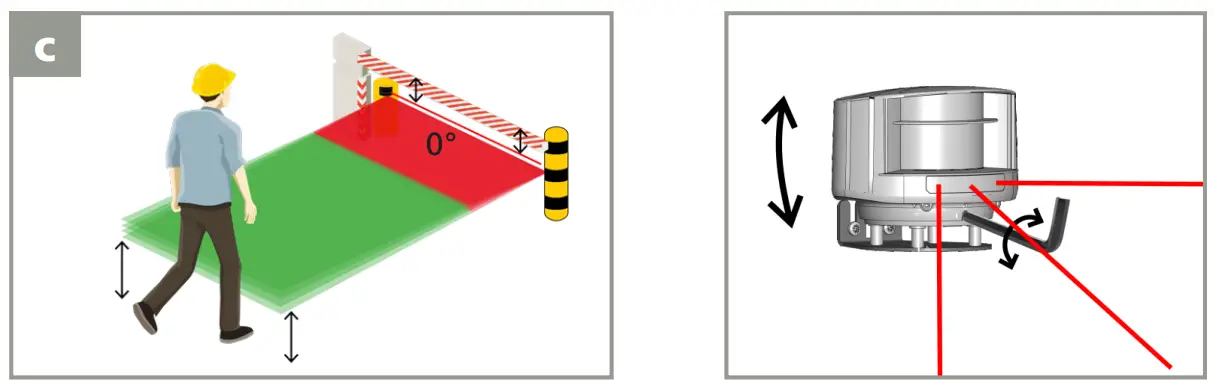 | |
| – The reference must be parallel to the barrier. – The beginning of the opening field should be approximately 15 inches above the ground. | Adjust the tilt angle of the detection field with the hex key if necessary. |
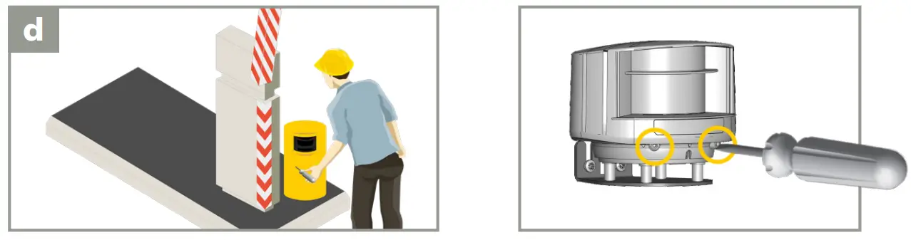 | |
| To finish, lock the sensor position using a screwdriver. | |
MOUNTING SIDE & REFERENCE
WITH REFERENCE
(RECOMMENDED)
WITHOUT REFERENCE
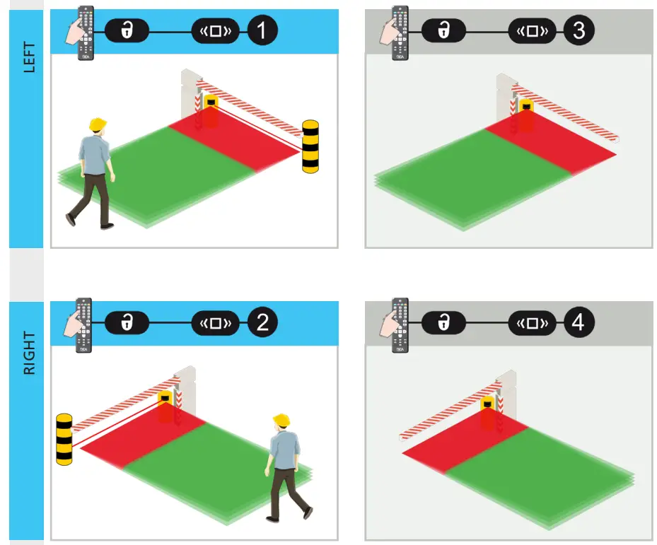
By default, the sensor automatically adjusts the width of the safety field based on the reference.
NOTE: Once determined, the reference point should not be altered. Any change to the reference point will cause the sensor’s reference to go into detection.
SAFETY FIELD
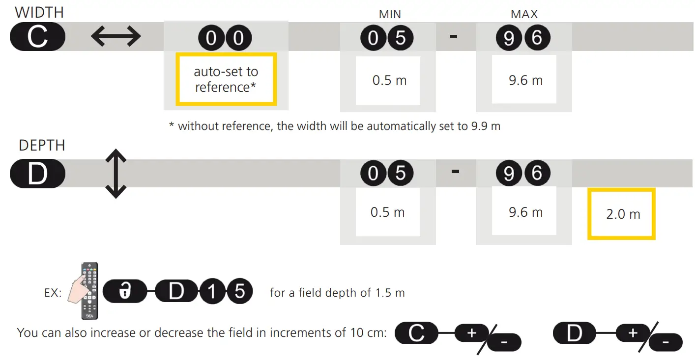
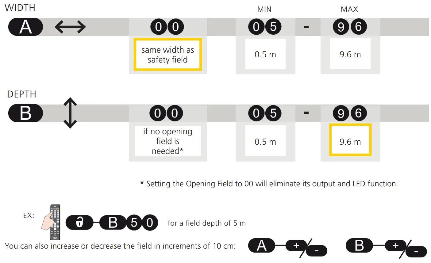
FIELD DIMENSIONS
Before launching a learn, the field dimensions can be adjusted by remote control.
Dimensions must be entered using the metric system – convert if necessary.
Value C must be adapted to the width of the barrier:
- when the reference point is farther away than the desired detection field width
- when a mounting side without reference has been selected
LEARN
Launch a learn by remote control. You have 3 seconds to step out of the detection field.
Then wait for the sensor to learn its environment (30 seconds).
During the learning, the detection field must be free of snow buildups, heavy rain, snowfall, fog or other moving objects.
If you walk along the detection area while they learn the function is active, the sensor memorizes the outline of the walk path and stores this as a new detection field. The shortest distance measured by each laser beam is stored by the sensor and determines the field limit.
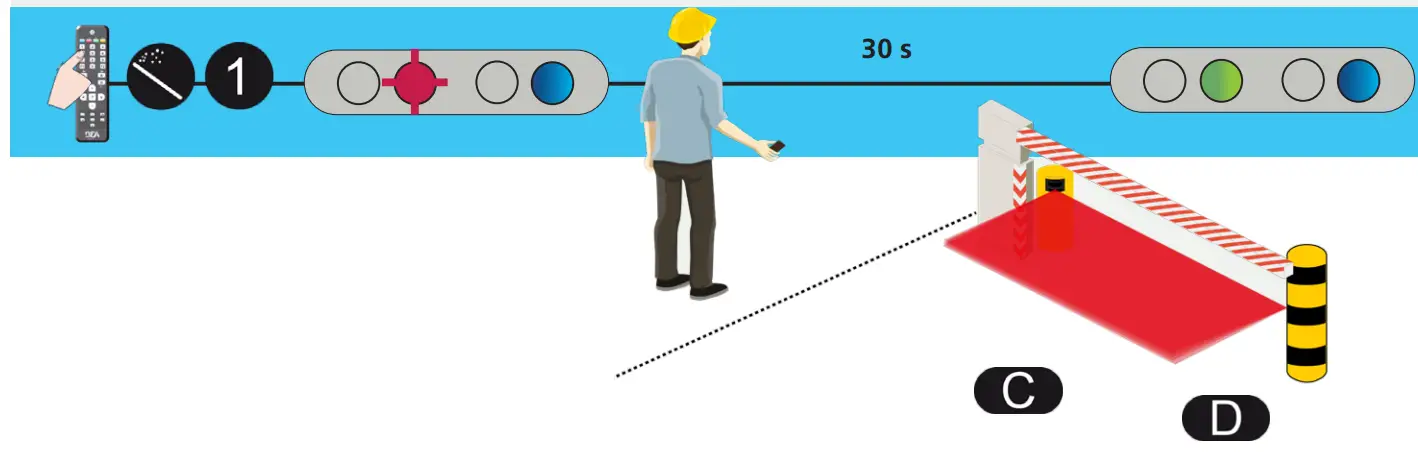
Once the sensor has finished the learn, make sure that the safety field is correctly configured and that the area around the barrier or gate is safe.
Always launch a new learn after adjusting the field dimensions.
If the safety field is the only protection against contact with the boom, the safety field of the sensor must be situated right under the barrier. This is only possible when the sensor is positioned correctly and the reference has been learned.
The safety field is necessary for the correct functioning of the installation. If the safety field is badly adjusted, the manufacturer of the sensor cannot be held responsible for the inappropriate functioning of the installation. Always verify the correct functioning of the safety field before leaving the premises.6
OPENING FIELD
FIELD DIMENSIONS
Before launching a learn, the field dimensions can be adjusted by remote control.
Dimensions must be entered using the metric system – convert if necessary.
LEARN
Launch a learn by remote control. You have 3 seconds to step out of the detection field.
Then wait for the sensor to learn its environment (45 seconds).
During the learning, the detection field must be free of snow buildups, heavy rain, snowfall, fog, or other moving objects.
If you walk along the detection area while they learn the function is active, the sensor memorizes the outline of the walk path and stores this as a new detection field. The shortest distance measured by each laser beam is stored by the sensor and determines the field limit.
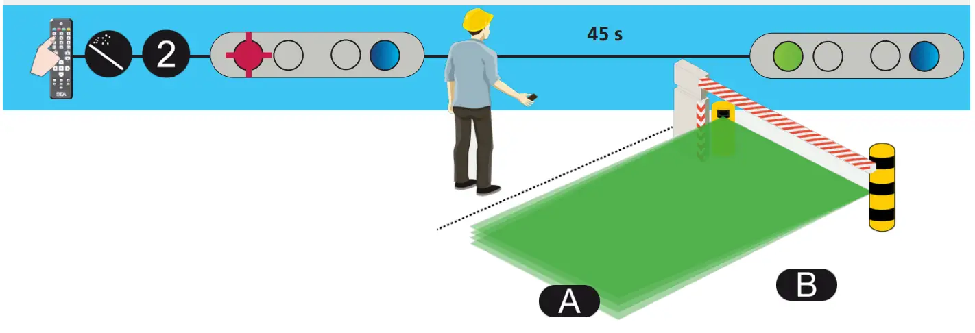
If the 1st red LED stays ON and no moving objects are in the detection field, reduce the opening field size or launch new learning.
![]() Always launch a new learn after adjusting the field dimensions.
Always launch a new learn after adjusting the field dimensions.
REMOTE CONTROL ADJUSTMENTS (OPTIONAL)
PEDESTRIAN FILTER opening field
Select value 3 or higher to reject pedestrians. All objects wider than the selected size will be detected. 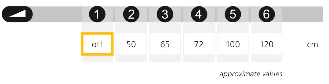
MAX. PRESENCE TIME opening field
STANDSTILL IN OPENING FIELD:
Select the amount of time R1 should stay active after an object becomes still in the opening field.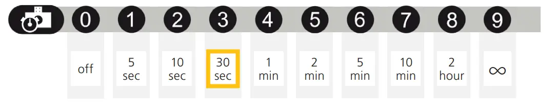
DETECTION DELAY opening field
ENVIRONMENT FILTER:
Increase value in case of heavy rain, snow, or moving objects in the environment.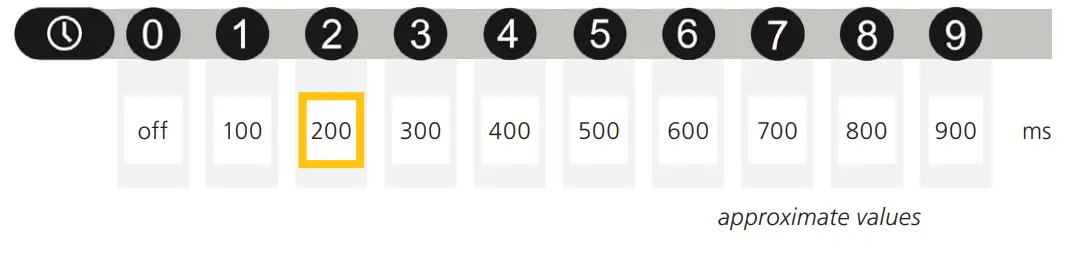
OUTPUT FUNCTION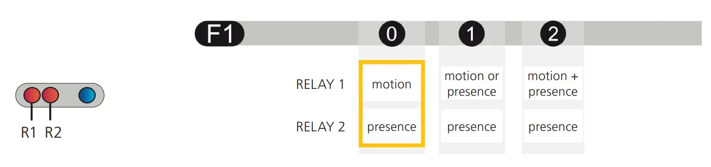
OUTPUT CONFIGURATION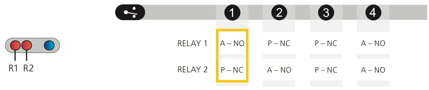
REMOTE CONTROL ADJUSTMENTS (OPTIONAL)
DETECTION TRAJECTORY opening field
| BIDIRECTIONAL | bidirectional detection approaching + departing | 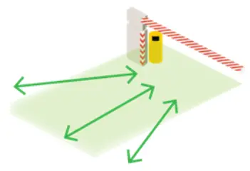 | 1 |
| UNI 400% | unidirectional detection only approaches in any direction | 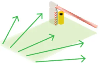 | 2 |
| UNI 200% | unidirectional detection only approaching the barrier/gate | 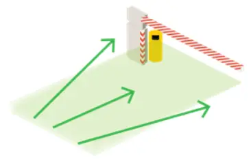 | 3 |
| UNI 100% | unidirectional detection only approaches within the width of the barrier/gate | 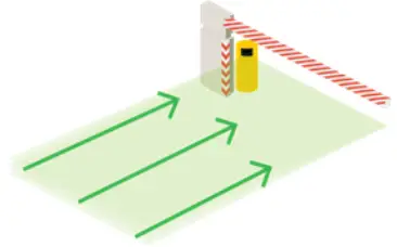 | 4 |
| UNI 50% | unidirectional detection only approaches towards the central zone of the barrier/gate | 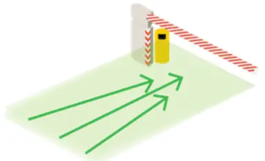 | 5 |
| UNI CENTER | unidirectional detection only approaches the center of the barrier/gate | 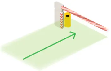 | 6 |
| UNI RIGHT | unidirectional detection only approaches the right side of the barrier/gate | 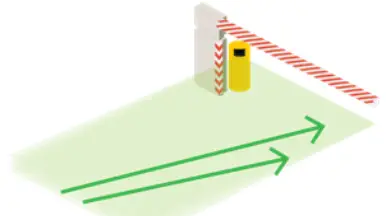 | 7 |
| UNI LEFT | unidirectional detection only approaches towards the left side of the barrier/gate | 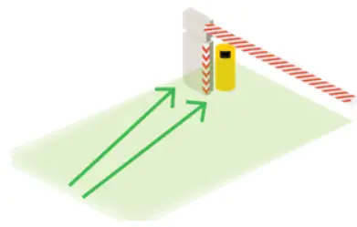 | 8 |
IMMUNITY
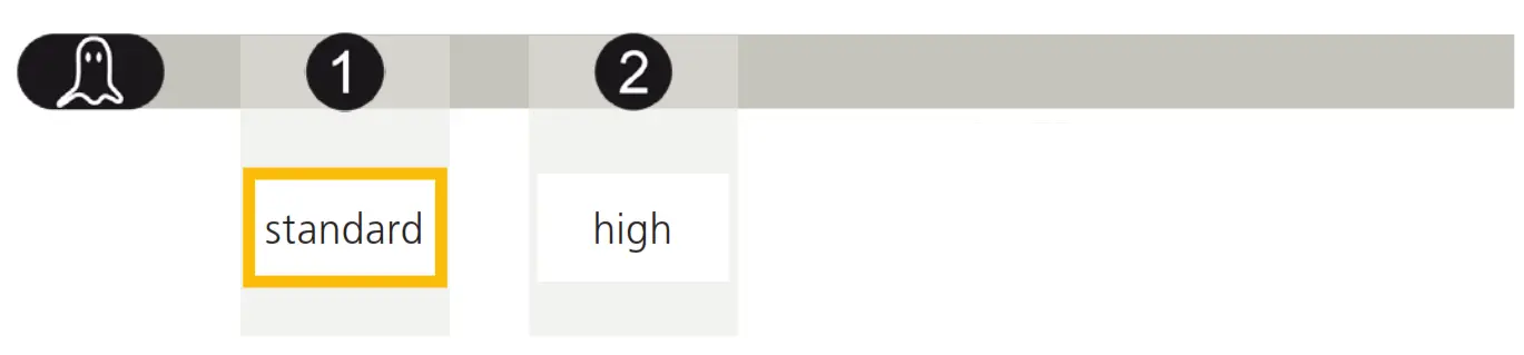
NOTE: Select “high” if fog is causing unwanted detections.
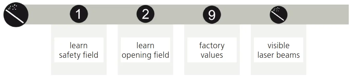
MAGIC WAND
TROUBLESHOOTING
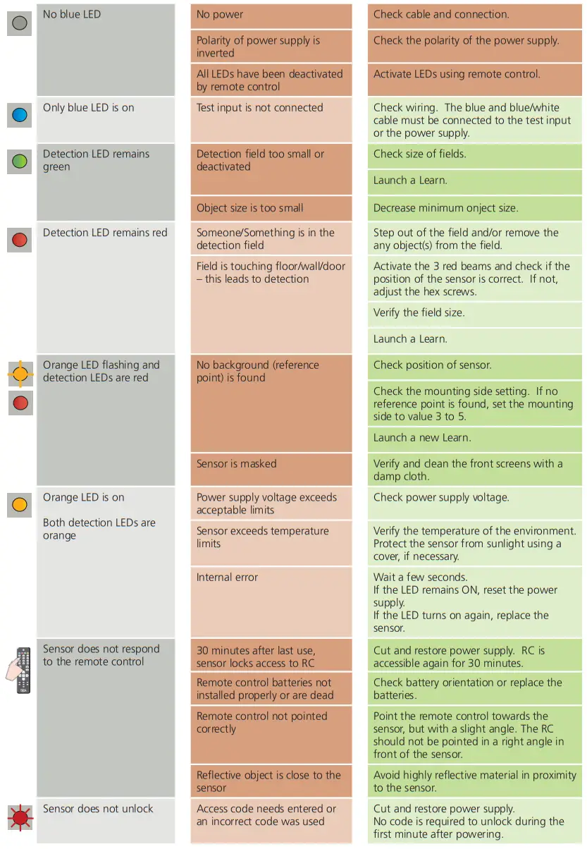

Can’t find your answer?
Visit www.beainc.com or scan QR code for Frequently Asked Questions!
TECHNICAL SPECIFICATIONS
| Technology: | laser scanner, time-of-flight measurement (4 laser curtains) |
| Detection mode: | motion and presence |
| Max. detection field: | 32’ x 32’ (9 ⁄ m) |
| Min. detection field (safety): | 1’ 8” ( 1 ⁄5 m) |
| Remission factor: | > 2% |
| Angular resolution: | 0.3516° |
| Emission characteristics IR laser: Red visible laser: | wavelength 905 nm; output power 0.10mW (CLASS 1) wavelength 635 nm; output power 0.95mW (CLASS 2) |
| Supply voltage: | 10 – 35 VDC |
| Power consumption: | < 5 W |
| Peak current @ power-on: | 1.8 A (max. 80 ms @ 35 V) |
| Cable length: | 33’ |
| Response time: motion detection: presence detection: | typ. 200 ms (adjustable) typ. 20 ms (max. 80 ms) |
| Output: Max. switching voltage: Max. switching current: Switching time: Output resistance: Voltage drop on output: Leakage current: | 2 electronic relays (galvanic-isolated – polarity-free) 35 VDC / 24 VAC 80 mA (resistive) tON = 5 ms; tOFF = 5 ms typ 30 Ω < 0.7 V @ 20 mA < 10 µA |
| Test input: Max. contact voltage: Voltage threshold: | 2 optocouplers (galvanic-isolated – polarity-free) 30 VDC (over-voltage protected) Log. H: > 8 VDC Log. L: < 3 VDC |
| LED signal: | 3 5 ⁄8”× 2 3 ⁄4”× 5”(W × H × D) mounting bracket: + 1 ⁄2” |
| Dimensions: | PC/ASA |
| Material: | Black |
| Color: | -45°, 0°, 45° |
| Mounting angles on bracket: | -5 – 5° (lockable) |
| Rotation angles on bracket: | -3 – 3° |
| Tilt angles on bracket: | NEMA 4 / IP65 |
| Protection degree: | NEMA 4 / IP65 |
| Temperature range: | powered: -22 – 140 °F (-30 – 60 ºC) unpowered: 14 – 140 °F (-10 – 60 ºC) |
| Humidity: | 0 – 95% non-condensing |
| Vibrations: | < 2G |
| Pollution on front screen: | max. 30%, homogenous |
| Norm conformity: | 2006/95/EC: LVD 2002/95/EC: RoHS 2004/108/EC: EMC IEC 60529:2001 IEC 60825-1:2007 IEC 60950-1:2005 IEC 61000-6-2:2005 IEC 61000-6-3:2006 |
BEA, INC. INSTALLATION/SERVICE COMPLIANCE EXPECTATIONS
BEA, Inc., the sensor manufacturer, cannot be held responsible for incorrect installations or incorrect adjustments of the sensor/device; therefore, BEA, Inc. does not guarantee any use of the sensor/device outside of its intended purpose.
BEA, Inc. strongly recommends that installation and service technicians be AAADM-certified for pedestrian doors, IDA-certified for doors/gates, and factory-trained for the type of door/gate system.
Installers and service personnel are responsible for executing a risk assessment following each installation/service performed, ensuring that the sensor/ device system performance is compliant with local, national, and international regulations, codes, and standards.
Once installation or service work is complete, a safety inspection of the door/gate shall be performed per the door/gate manufacturer’s recommendations and/or per AAADM/ANSI/DASMA guidelines (where applicable) for best industry practices. Safety inspections must be performed during each service call – examples of these safety inspections can be found on an AAADM safety information label (e.g. ANSI/DASMA 102, ANSI/DASMA 107, UL294, UL325, and International Building Code).
Verify that all appropriate industry signage, warning labels, and placards are in place.
![]()
Tech Support & Customer Service: 1-800-523-2462
General Tech Questions: [email protected] | Tech Docs: www.BEAsensors.com
©BEA | Original Instructions | PLEASE KEEP FOR FURTHER USE – DESIGNED FOR COLOR PRINTING
75.5984.04 LZR-H100 20220105


