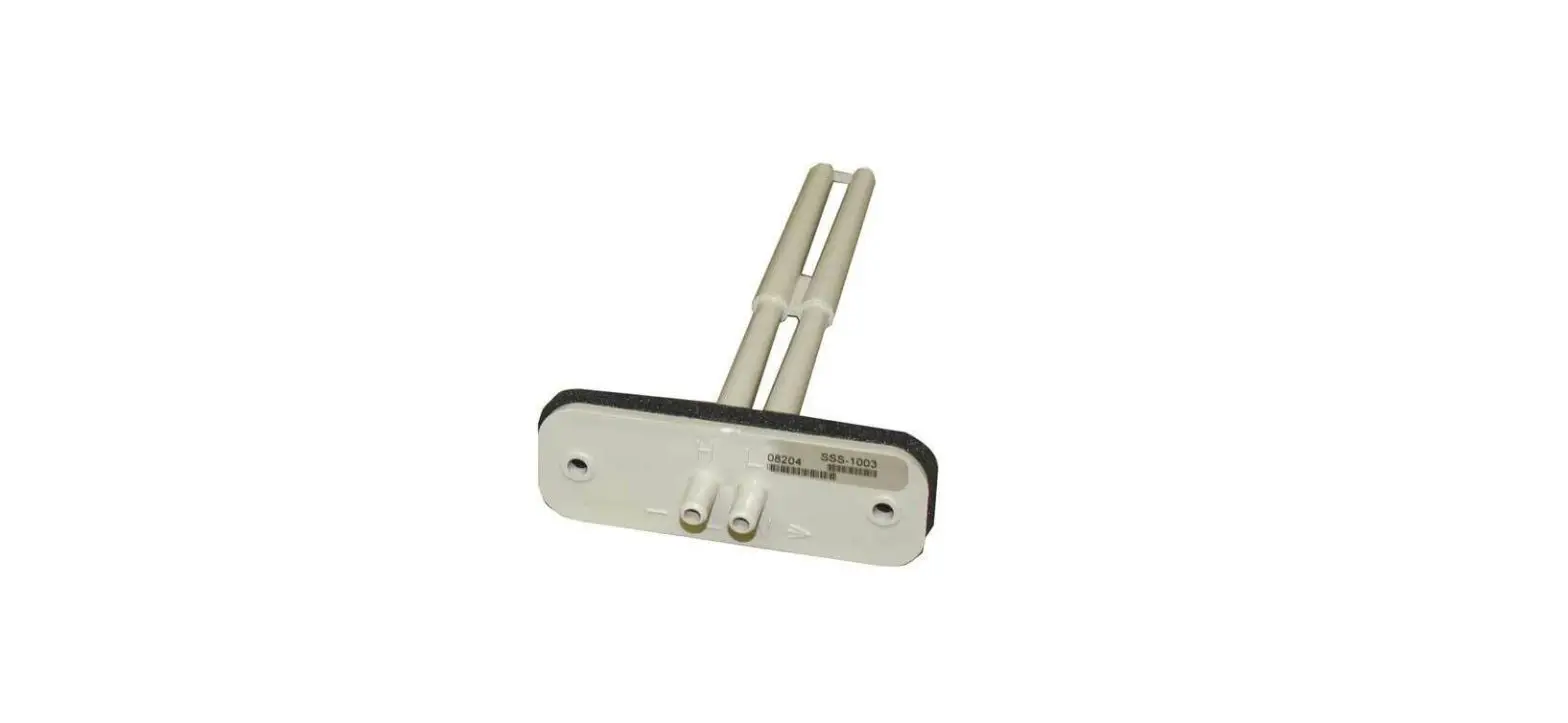
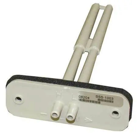
 KMC SSS-1000 Series Differential Pressure Flow Sensors
Installation
Mounting for Differential Pressure Flow To mount the sensor for differential pressure:
- Determine the duct’s flow direction and install the sensor based on the sensor’s flow arrow imprint.
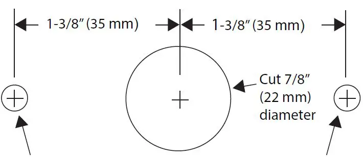
NOTE: The sensor must be mounted with the FLOW arrow imprint pointing in the direction of the air flow. - Cut a 7/8″ (22 mm) hole in the duct to accept the sensor’s probes.
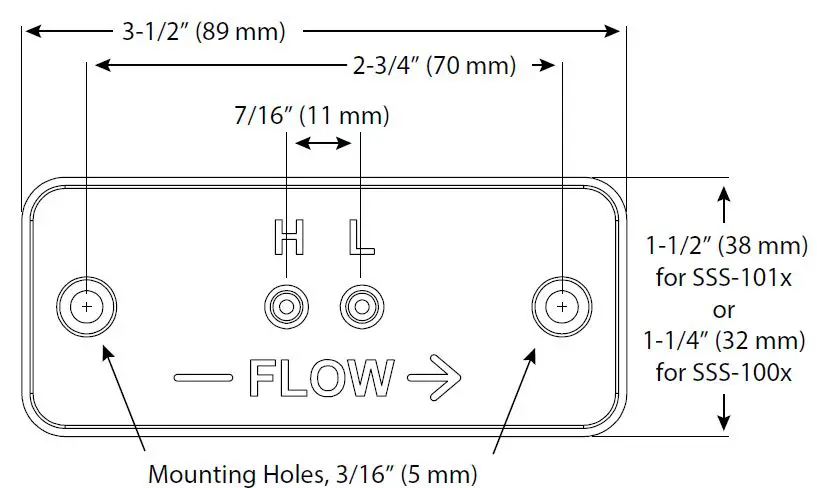
- Attach the sensor to the duct using two self-tapping screws inserted through the sensor’s 3/16″ (5 mm) mounting holes.


Connections
Use appropriately sized polyethylene tubing to connect the sensor to the controller:
- For connecting SSS-10xx sensors with CSC-3000 series, CSP-4000/5000 series, KMD-7000 series, and BAC-7000/8000/9000 series controllers, use a barb union adapter and tubing sized appropriately to the sensor and controller. For maximum accuracy in the CSP-5000 series, KMD-7000 series, and BAC-7000 series control-lers, the 3/8″ OD tubing between the sensor and the adapter should be as short as possible, and the 1/4″ OD tubing from the adapter to the controller should be 24″ long (on both the High and the Low sides).
- OR use the equivalent SSS-101x sensor and just 1/4″ OD tubing (no adapter is necessary). For maximum accuracy in the CSP-5000 series, KMD-7000 series, and BAC-7000 series controllers, the 1/4″ OD tubing from the sensor to the controller should be 24″ long (on both the High and the Low sides).
NOTE:
For other controllers, the length of the tubing should not be longer than necessary.
NOTE:
CSC-2000 series controllers have ports for 3/8″ tubing (the same as the SSS-10xx sensors).
Check that there are no sharp bends in the tubing at any connection. Bends and creases may leak as tubing ages.
- Connect the Port “H” to the “High” input on the VAV controller.
- Connect the Port “L” to the “Low” input on the VAV controller.
Mounting for Static Pressure
To mount the sensor for static pressure:
- Determine the duct’s flow direction and install the sensor so that the FLOW arrow imprint is perpendicular to the direction of the air flow.
NOTE: The FLOW arrow imprint on the sensor can point either up or down.
NOTE: It is recommended that an indication or marking be applied to the SSS-10xx probe to indicate the intended orientation. - Cut a 7/8″ (22 mm) hole in the duct to accept the sensor’s probes.
- Attach the sensor to the duct using two self-tapping screws inserted through the sensor’s 3/16″ (5 mm) mounting holes.
NOTE: If mounting an SSS-10xx sensor perpendicular to a relatively small diameter round duct, take care not to break the sensor by overtightening the screws and overflexing the plastic sensor mount.
Connections
Using appropriately sized polyethylene tubing, connect either the H or L port on the sensor to the High port on the controller.
NOTE: The other port of the sensor is left unconnected and open to air.
NOTE: Tubing should be free of kinks and restrictions.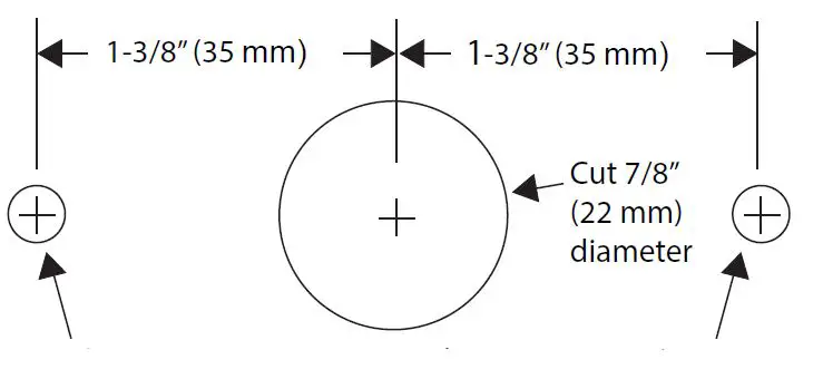
Select Specifications
Material
Light gray (SSS-100x) or almond (SSS-101x) ABS/polycarbonate (UL94-5V)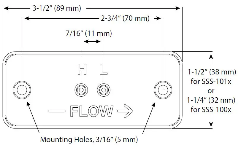
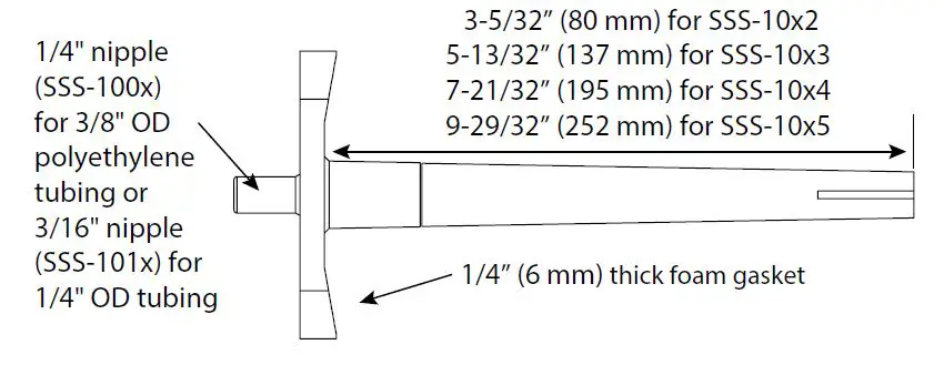
Connection
1/4″ nipple (SSS-100x) for 3/8″ OD polyethylene tubing or 3/16″ nipple (SSS-101x) for 1/4″ OD tubing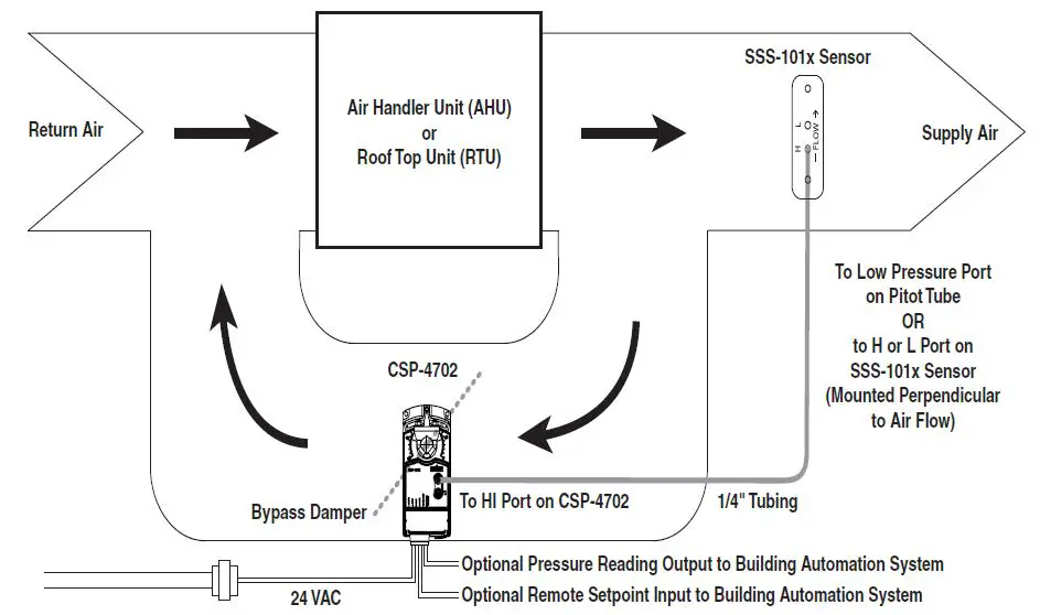
K Factors
Refer to the data sheet for addi-tional information!
NOTE: The appropriate “K” factor for the sensor depends upon the type of setup required by the VAV controller with which it will be used:
- For VAV controllers that require KCFM for setup, refer to the “Cubic Feet Per Minute (CFM)” chart below and the device documentation for additional information. For rectangular ducts, KCFM = KFPM x (W” x H”/144) (with duct cross-section measurements in inches).
- For VAV controllers that require KFPM for setup, refer to the “Feet Per Minute” chart below and the device documentation for additional information.
| “Cubic Feet Per Minute (CFM)” K Factors | ||||
| Round Duct Size (Diameter) | KCFM Factor | |||
| SSS-10×2 | SSS-10×3 | SSS-10×4 | SSS-10×5 | |
| 4 | 301 | NA | NA | NA |
| 5 | 470 | NA | NA | NA |
| 6 | 677 | 648 | NA | NA |
| 7 | 922 | 882 | NA | NA |
| 8 | 1204 | 1152 | 1117 | NA |
| 9 | 1524 | 1458 | 1414 | NA |
| 10 | 1882 | 1800 | 1745 | 1745 |
| 12 | 2710 | 2592 | 2513 | 2513 |
| 14 | 3688 | 3528 | 3421 | 3421 |
| 16 | 4817 | 4608 | 4468 | 4468 |
| 18 | 6097 | 5832 | 5655 | 5655 |
| 22 | 9107 | 8711 | 8447 | 8447 |
| 24 | 10838 | 10367 | 10053 | 10053 |
| “Feet Per Minute” K Factors | |
| Sensor Model | KFPM |
| SSS-10×2 | 3450 |
| SSS-10×3 | 3300 |
| SSS-10×4 | 3200 |
| SSS-10×5 | 3200 |
Maintenance
Sensing orifices must be kept free of dust accumulation or debris. The sensors are designed for dependable, long-term reliability and performance.
More Information
For additional K factor and other information, see the data sheet for the SSS-1000 series on the KMC web site (www. kmccontrols.com).
Important Notices
The KMC logo and KMC Controls are registered trademarks of KMC Controls, Inc.
All rights reserved. No part of this publication may be reproduced, transmitted, transcribed, stored in a retrieval system, or translated into any language in any form by any means without the written permission of KMC Controls, Inc. The material in this document is for information purposes only. The contents and the product it describes are subject to change without notice. KMC Controls, Inc. makes no representations or warranties with respect to this docu-ment. In no event shall KMC Controls, Inc. be liable for any damages, direct or incidental, arising out of or related to the use of this document.
KMC Controls, Inc.
KMC SSS-1000 Series Differential Pressure Flow Sensors
Installation
Mounting for Differential Pressure Flow
To mount the sensor for differential pressure:
- Determine the duct’s flow direction and install the sensor based on the sensor’s flow arrow imprint.
NOTE: The sensor must be mounted with the FLOW arrow imprint pointing in the direction of the air flow. - Cut a 7/8″ (22 mm) hole in the duct to accept the sensor’s probes.
- Attach the sensor to the duct using two self-tapping screws inserted through the sensor’s 3/16″ (5 mm) mounting holes.
Connections
Use appropriately sized polyethylene tubing to connect the sensor to the controller:
- For connecting SSS-10xx sensors with CSC-3000 series, CSP-4000/5000 series, KMD-7000 series, and BAC-7000/8000/9000 series controllers, use a barb union adapter and tubing sized appropriately to the sensor and controller. For maximum accuracy in the CSP-5000 series, KMD-7000 series, and BAC-7000 series control-lers, the 3/8″ OD tubing between the sensor and the adapter should be as short as possible, and the 1/4″ OD tubing from the adapter to the controller should be 24″ long (on both the High and the Low sides).
- OR use the equivalent SSS-101x sensor and just 1/4″ OD tubing (no adapter is necessary). For maximum accuracy in the CSP-5000 series, KMD-7000 series, and BAC-7000 series controllers, the 1/4″ OD tubing from the sensor to the controller should be 24″ long (on both the High and the Low sides).
NOTE:
For other controllers, the length of the tubing should not be longer than necessary.
NOTE:
CSC-2000 series controllers have ports for 3/8″ tubing (the same as the SSS-10xx sensors).
Check that there are no sharp bends in the tubing at any connection. Bends and creases may leak as tubing ages.
- Connect the Port “H” to the “High” input on the VAV controller.
- Connect the Port “L” to the “Low” input on the VAV controller.
Mounting for Static Pressure
To mount the sensor for static pressure:
- Determine the duct’s flow direction and install the sensor so that the FLOW arrow imprint is perpendicular to the direction of the air flow.
NOTE: The FLOW arrow imprint on the sensor can point either up or down.
NOTE: It is recommended that an indication or marking be applied to the SSS-10xx probe to indicate the intended orientation. - Cut a 7/8″ (22 mm) hole in the duct to accept the sensor’s probes.
- Attach the sensor to the duct using two self-tapping screws inserted through the sensor’s 3/16″ (5 mm) mounting holes.
NOTE: If mounting an SSS-10xx sensor perpendicular to a relatively small diameter round duct, take care not to break the sensor by overtightening the screws and overflexing the plastic sensor mount.
Connections
Using appropriately sized polyethylene tubing, connect either the H or L port on the sensor to the High port on the controller.
NOTE: The other port of the sensor is left unconnected and open to air.
NOTE: Tubing should be free of kinks and restrictions.
Select Specifications
Material
Light gray (SSS-100x) or almond (SSS-101x) ABS/polycarbonate (UL94-5V)
Connection
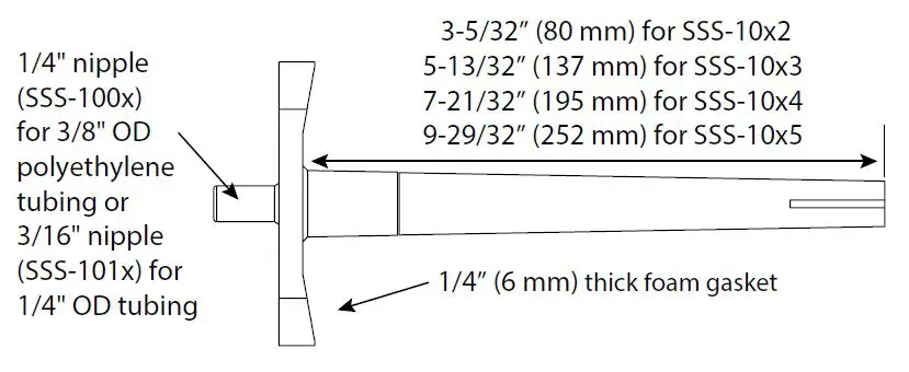
1/4″ nipple (SSS-100x) for 3/8″ OD polyethylene tubing or 3/16″ nipple (SSS-101x) for 1/4″ OD tubing
K Factors
Refer to the data sheet for addi-tional information!
NOTE: The appropriate “K” factor for the sensor depends upon the type of setup required by the VAV controller with which it will be used:
- For VAV controllers that require KCFM for setup, refer to the “Cubic Feet Per Minute (CFM)” chart below and the device documentation for additional information. For rectangular ducts, KCFM = KFPM x (W” x H”/144) (with duct cross-section measurements in inches).
- For VAV controllers that require KFPM for setup, refer to the “Feet Per Minute” chart below and the device documentation for additional information.
| “Cubic Feet Per Minute (CFM)” K Factors | ||||
| Round Duct Size (Diameter) | KCFM Factor | |||
| SSS-10×2 | SSS-10×3 | SSS-10×4 | SSS-10×5 | |
| 4 | 301 | NA | NA | NA |
| 5 | 470 | NA | NA | NA |
| 6 | 677 | 648 | NA | NA |
| 7 | 922 | 882 | NA | NA |
| 8 | 1204 | 1152 | 1117 | NA |
| 9 | 1524 | 1458 | 1414 | NA |
| 10 | 1882 | 1800 | 1745 | 1745 |
| 12 | 2710 | 2592 | 2513 | 2513 |
| 14 | 3688 | 3528 | 3421 | 3421 |
| 16 | 4817 | 4608 | 4468 | 4468 |
| 18 | 6097 | 5832 | 5655 | 5655 |
| 22 | 9107 | 8711 | 8447 | 8447 |
| 24 | 10838 | 10367 | 10053 | 10053 |
| “Feet Per Minute” K Factors | |
| Sensor Model | KFPM |
| SSS-10×2 | 3450 |
| SSS-10×3 | 3300 |
| SSS-10×4 | 3200 |
| SSS-10×5 | 3200 |
Maintenance
Sensing orifices must be kept free of dust accumulation or debris. The sensors are designed for dependable, long-term reliability and performance.
More Information
For additional K factor and other information, see the data sheet for the SSS-1000 series on the KMC web site (www. kmccontrols.com).
Important Notices
The KMC logo and KMC Controls are registered trademarks of KMC Controls, Inc.
All rights reserved. No part of this publication may be reproduced, transmitted, transcribed, stored in a retrieval system, or translated into any language in any form by any means without the written permission of KMC Controls, Inc. The material in this document is for information purposes only. The contents and the product it describes are subject to change without notice. KMC Controls, Inc. makes no representations or warranties with respect to this docu-ment. In no event shall KMC Controls, Inc. be liable for any damages, direct or incidental, arising out of or related to the use of this document.
KMC Controls, Inc.
19476 Industrial Drive
New Paris, IN 46553
574.831.5250
www.kmccontrols.com
[email protected]
19476 Industrial Drive
New Paris, IN 46553
574.831.5250
www.kmccontrols.com
[email protected]


