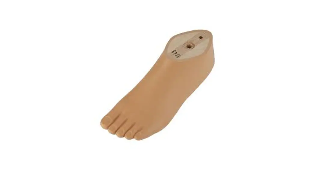
![]() SACH Foot Men Toes
SACH Foot Men Toes
Instruction Manual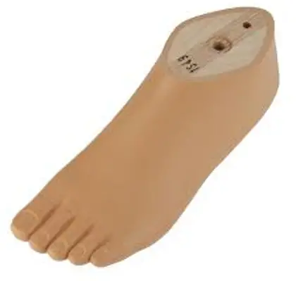
1S49, 1S66, 1S67, 1S90 SACH
 |  |
 |  |
Product Description
INFORMATION
Date of last update: 2021-08-02
- Please read this document carefully before using the product and observe the safety notices.
- Instruct the user on the safe use of the product.
- Please contact the manufacturer if you have questions about the product or in case of problems.
- Report each serious incident related to the product to the manu facturer and to the relevant authority in your country. This is par particularly important when there is a decline in the health state.
- Please keep this document for your records.
1.1 Construction and Function
The 1S49, 1S66, and 1S90 SACH prosthetic feet (solid ankle cushion heel) are suitable for use in both modular and exoskeletal prostheses.
The functional properties are achieved through the combination of a contoured core and functional foam.
1.2 Combination possibilities
This prosthetic component is compatible with Ottobock’s system of modular connectors. Functionality with components of other manufac turers that have compatible modular connectors has not been tested.
| Allowable ankle blocks and screw connections | |
| Foot size [cm] | Reference number (ankle block and screw connection) |
| 24 to 30 | 2K34=30 and 2Z22=M10 |
| Allowable foot adapters | ||
| Size [cm] | Body weight [kg] | Allowable foot adapter |
| 21 to 30 | 100 | 2R8=M10, 2R31=M10, 2R54=M10 |
| 26 to 30 | 101 to 125 | 2R8=M10, 2R31=M10 |
Intended use
2.1 Indications for use
The product is intended exclusively for lower limb endoprosthetic fit things.
2.2 Area of application
Our components perform optimally when paired with appropriate components based on weight and mobility grades identifiable by our MOBIS classification information and which have appropriate modular connectors.![]() The product is recommended for mobility grade 1 (indoor walker) and mobility grade 2 (restricted outdoor walker).
The product is recommended for mobility grade 1 (indoor walker) and mobility grade 2 (restricted outdoor walker).
- The maximum approved body weight is specified in the technical data (see page 14).
2.3 Environmental conditions
Storage and transport
Temperature range –20 °C to +60 °C (–4 °F to +140 °F), relative humidity 20 % to 90 %, no mechanical vibrations or impacts
Allowable environmental conditions
Temperature range: –10 °C to +45 °C (14 °F to 113 °F) Moisture: relative humidity: 20% to 90%, non-condensing
Unacceptable environmental conditions
Chemicals/liquids: fresh water, salt water, perspiration, urine, acids, soapsuds, chlorine water
Solids: dust, sand, highly hygroscopic particles (e. g. talcum)
2.4 Lifetime
The product was tested by the manufacturer with 2 million load cycles. Depending on the user’s activity level, this corresponds to a maximum lifetime of 3 years.
Safety
3.1 Explanation of warning symbols
![]() CAUTION Warning regarding possible risks of accident or injury.
CAUTION Warning regarding possible risks of accident or injury.
NOTICE Warning regarding possible technical damage.
3.2 General safety instructions
![]() CAUTION
CAUTION
Risk of injury and risk of product damage
- To avoid the risk of injury and product damage, do not use the product beyond the tested lifetime.
- To avoid the risk of injury and product damage, only use the product for a single patient.
- Comply with the product’s field of application and do not expose it to excessive strain (see page 9).
- Note the combination possibilities/combination exclusions in the instructions for use of the products.
NOTICE!
Risk of product damage and limited functionality
- To prevent mechanical damage, use caution when working with the product.
- If you suspect the product is damaged, check it for proper func tion and readiness for use.
- Do not use the product if its functionality is restricted. Take suit able measures (e.g. cleaning, repair, replacement, inspection by the manufacturer or a specialist workshop).
- Do not expose the product to prohibited environmental condi tions.
- Check the product for damage if it has been exposed to prohib cited environmental conditions.
- Do not use the product if it is damaged or in a questionable con edition. Take suitable measures (e.g. cleaning, repair, replace ment, inspection by the manufacturer or a specialist workshop).
Signs of changes in or loss of functionality during use Decreased forefoot resistance or changes in roll-over behavior are noticeable indications of loss of functionality.
Scope of delivery
| Quantity | Designation |
| 1 | Instructions for use |
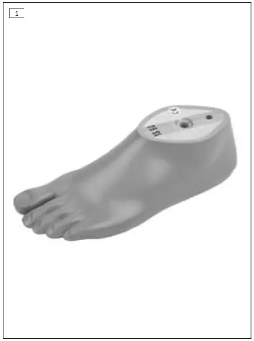
| 1 | Prosthetic foot |
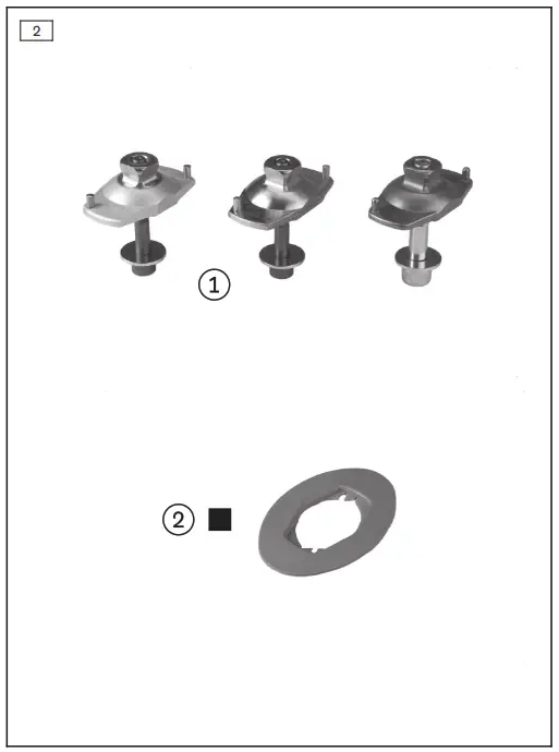
| Fig. | Item | Designation | Reference number |
| 2 | 1 | Foot adapter with screw connection | 2R8*, 2R31*, 2R54* |
| 2 | 2 | Connection plate | 2R14 |
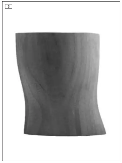
| 3 | — | Ankle block (exoskeletal design) | 2K34=* |
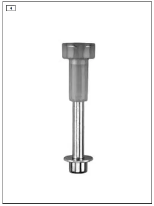
| 4 | — | Screw connection for ankle block (exoskeletal design) | 2Z22=M10 |
| — | — | Ottobock special adhesive with hardener | 636W28 or 636W18 and 636W19 |
Preparing the product for use
CAUTION
Incorrect alignment or assembly
Risk of injury due to damaged prosthetic components
- Observe the alignment and assembly instructions.
INFORMATION
- Not all of the materials may be available in your country. In this case, please contact the local branch of the manufacturer to obtain information on alternative materials.
5.1 Installing the foot adapter
► Install the foot adapter on the prosthetic foot according to its instructions for use.
5.2 Installing the ankle block (exoskeletal design)
> Required materials: Screw connection (see page 11), 710D21 torque wrench, 40 grit sandpaper, 617H21 sealing resin, 617P37 hardener powder, suitable solvent (e.g. 634A28), only for
1WR95: 636W17 plastic adhesive
- Insert the threaded socket of the screw connection in the proximal side of the hole in the ankle block.
- Insert the screw on the foot sole side in the prosthetic foot and screw the ankle block to the prosthetic foot (mounting torque: 30 Nm).
- Conduct the fitting of the ankle block.
- Loosen the screw connection between the prosthetic foot and the ankle block.
- Sand the ankle block according to the contour of the prosthetic foot.
- Roughen the connection surface of the prosthetic foot in a – p direction using sandpaper.
- Remove the dust from the sanded surfaces.
- Mix the sealing resin with 2% to 3% hardener powder for the con nection between the ankle block and the prosthetic foot.
- INFORMATION: Do not put the resin in the hole for the screw connection.
Apply the resin evenly to the connection surfaces of the ankle block and prosthetic foot. At least 2 applications are required due to the absorbency of the wood. - When the resin is slightly cured (threads on the spatula), align the ankle block and prosthetic foot with each other.
- Insert the screw on the foot sole side in the prosthetic foot and screw the ankle block to the prosthetic foot (mounting torque: 30 Nm).
- Wipe off the resin that comes out of the joint using a cloth.
- 1WR95 only: Apply plastic adhesive to the plug for the screw connection and press it fully into the prosthetic foot.
- Remove any remnants of the adhesive using a suitable solvent.
- Allow the adhesive to cure.
5.3 Alignment
NOTICE
Grinding the prosthetic foot
Premature wear resulting from damage to the prosthetic foot
- Do not grind the prosthetic foot.
5.3.1 Bench Alignment
TT bench alignment
| Bench alignment process | |
| Required materials: 662M4 goniometer, 743S12 heel height measuring apparatus, 743A80 50:50 gauge, alignment apparatus (e.g. 743L200 L.A.S.A.R. Assembly or 743A200 PROS.A. Assembly) | |
| Perform the assembly and alignment of the prosthetic components in the alignment apparatus according to the following specifications: | |
| Sagittal plane | |
| 1 | Heel height: Effective heel height (shoe heel height – sole the thickness of forefoot) + 5 mm |
| 2 | Exterior foot rotation: approx. 5° |
| 3 | Anterior placement, middle of the prosthetic foot to the alignment- ment reference line: 30 mm |
| Bench alignment process | |
| 4 | Connect the prosthetic foot and prosthetic socket using the chosen adapters. The instructions for use of the adapters must be observed. |
| o | Determine the center of the prosthetic socket with the 50:50 gauge. Align the prosthetic socket centrally to the alignment reference line. Socket flexion: Individual residual limb flexion + 5° |
| Frontal plane | |
| 6 | Alignment reference line of the prosthetic foot: between the big toe and second toe Alignment reference line of prosthetic socket: along the lateral patella edge |
| 0 | Observe the abduction or adduction position. |
TF bench alignment
- Observe the information in the prosthetic knee joint instructions for use.
5.3.2 Static Alignment
- Ottobock recommends checking the alignment of the prosthesis using the L.A.S.A.R. Posture and adapting it as needed.
- If necessary, the alignment recommendations (TF modular leg prostheses: 646F219*, TT modular leg prostheses: 646F336*) may be requested from Ottobock.
5.3.3 Dynamic Trial Fitting
- Adapt the alignment of the prosthesis in the frontal plane and the sagittal plane (e.g. by making angle or slide adjustments) to ensure an optimum gait pattern.
- TT fittings: Make sure that physiological knee movement in the sagittal and frontal plane is achieved when the leg begins to bear weight after the heel strike. Avoid medial movement of the knee joint. If the knee joint moves in the medial direction in the first half of the stance phase, move the prosthetic foot in the medial direc tion. If the medial movement occurs in the second half of the stance phase, reduce the exterior rotation of the prosthetic foot.
5.4 Optional: Installing the foam cover
The foam cover sits between the prosthetic socket and the prosthetic foot.
It is cut longer in order to compensate for the movements of the pros thetic foot and prosthetic knee joint. During flexion of the prosthetic knee joint, the foam cover undergoes posterior compression and anterior elongation. The foam cover should be stretched as little as possible in order to increase its service life. There is a connecting ele
ment (such as a connection plate, connection cap or connection cov er) on the prosthetic foot.
> Required materials: degreasing cleaner (e.g. 634A58 isopropyl alcohol), 636N9 contact adhesive or 636W17 plastic adhesive
- Measure the length of the foam cover on the prosthesis and add the length allowance.
TT prostheses: Distal allowance for movement of the prosthetic foot.
TF prostheses: Allowance proximal of the knee rotation point for flexion of the prosthetic knee joint and distal allowance for move ment of the prosthetic foot. - Cut the pre-shaped foam cover to length and fit it in the proximal area on the prosthetic socket.
- Pull the foam cover over the prosthesis.
- Set the connecting element onto the foot shell or prosthetic foot.
Depending on the version, the connecting element engages in the edge or rests on the foot adapter. - Install the prosthetic foot on the prosthesis.
- Mark the outer contour of the connecting element on the distal face of the foam cover.
- Disassemble the prosthetic foot and remove the connecting ele ment.
- Clean the connecting element using a degreasing cleaner.
- Glue the connecting element onto the distal face of the foam cov er according to the marked outer contour.
- Let the glue dry (approx. 10 minutes).
- Install the prosthetic foot and adapt the exterior cosmetic shape.
Take into account compression caused by cosmetic stockings or SuperSkin.
Cleaning
- Clean the product with a damp, soft cloth.
- Dry the product with a soft cloth.
- Allow to air dry in order to remove residual moisture.
Maintenance
- A visual inspection and functional test of the prosthetic compon ents should be performed after the first 30 days of use.
- Inspect the entire prosthesis for wear during normal consulta tions.
- Conduct annual safety inspections.
Disposal
In some jurisdictions, it is not permissible to dispose of the product with unsorted household waste. Improper disposal can be harmful to health and the environment. Observe the information provided by the responsible authorities in your country regarding return, collection, and disposal procedures.
Legal information
All legal conditions are subject to the respective national laws of the country of use and may vary accordingly.
9.1 Liability
The manufacturer will only assume liability if the product is used in accordance with the descriptions and instructions provided in this document. The manufacturer will not assume liability for damage caused by disregarding the information in this document, particularly due to improper use or unauthorized modification of the product.
9.2 CE conformity
The product meets the requirements of Regulation (EU) 2017/745 on medical devices. The CE declaration of conformity can be down loaded from the manufacturer’s website.
Technical data
| Reference number | 1549 | 1566 | 1590 | ||||||||
| Heel height [mm] | 10 ± 5 | 18 ± 5 | 10 ± 5 | ||||||||
| Mobility grade | 1 + 2 | ||||||||||
| Colors | All: beige (4), 1S90 only: brown (16) | ||||||||||
| Size [cm] | 21 | 22 | 23 | 24 | 25 | 26 | 27 | 28 | 29 | 30 | |
| System height with adapter | 52 | 55 | 58 | 61 | 64 | 67 | 70 | 72 | 74 | 76 | |
| Build height with adapter | 70 | 73 | 76 | 79 | 82 | 85 | 88 | 90 | 92 | 94 | |
| Max. body weight [kg] | 100 | 125 | |||||||||
| Weight without foot adapter [g] | |||||||||||
| 1S49 | 2- 65 | 2- 90 | 3- 30 | 3- 65 | 3- 90 | 4- 75 | 5- 35 | 5- 75 | – | – | |
| 1S66 | – | 3- 25 | 3- 25 | 3- 60 | 3- 95 | 4- 85 | 5- 55 | 5- 65 | 6- 25 | 6- 25 | |
| 1S67 | – | 3- 30 | 3- 65 | 4- 00 | 4- 40 | 5- 30 | – | – | – | – | |
| Size [cm] | 21 | 22 | 23 | 24 | 25 | 26 | 27 | 28 | 29 | 30 |
| 1S90 | – | 3 00 | 3 30 | 3 80 | 4 20 | 4 60 | 5 45 | 6 35 | – | – |
![]() ………………………………………………………………………………….
………………………………………………………………………………….
………………………………………………………………………………………..
![]() Ottobock SE & Co. KGaA
Ottobock SE & Co. KGaA
Max-Näder-Straße 15 · 37115 Duderstadt · Germany
T +49 5527 848-0
F +49 5527 848-3360
[email protected]
www.ottobock.com
© Ottobock · 647G355=all_INT-17-2109


