![]()
Quick Start Guide
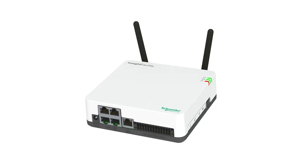
InsightFacility
https://solar.schneider-electric.com/product/InsightFacility/
Introduction
InsightFacility is a multi-function communication device that provides an overall view of system performance for residential power monitoring systems. It also provides a communications gateway between a network of XanbusTM-enabled devices and Modbus devices. Operators can configure the InsightFacility system and monitor performance with third-party software packages and building management systems.
 WARNING
HAZARD OF ELECTRIC SHOCK, EXPLOSION, ARC FLASH, AND FIRE
- Connect only to Safety Extra Low Voltage (SELV) circuits and limited power sources.
- All wiring must be done by qualified personnel to ensure compliance with all applicable installation codes and regulations.
- For Indoor Use Only.
- Do not disassemble. No user-serviceable parts inside.
Failure to follow these instructions can result in death, serious injury, or equipment damage.
Other features of InsightFacility include: compatibility, a real-time clock, a nonvolatile memory, firmware storage and upgrade capability, and cloud storage capability. For more information, see the Owner’s Guide (go to https://solar.schneiderelectric.com/product/InsightFacility/> Downloads).
Material List
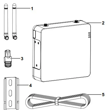
| Item | |
| 1 | Removable antennas |
| 2 | InsightFacility unit |
| 3 | Network terminator |
| 4 | 75 mm DIN rail |
| 5 | Ethernet cable (CAT5e) |
| not shown | •BMS CAN terminator •26-pin connector (see 26-Pin Connector Pinouts on page 2) |
| not supplied | Power adaptor: Manufacturer: CUI P/N: SMI18-12-V-P5 Description: AC-DC PowerSupply, 12Vdc Output Voltage, 1.6Adc Output Current |
NOTE:
- Do not discard the packaging box.
- The Wi-Fi password is printed on the unit.
- Install the antennas before turning on the unit.
DANGER
HAZARD OF ELECTRIC SHOCK, EXPLOSION, ARC FLASH, AND FIRE
This document is in addition to, and incorporates by reference, the relevant product manuals for InsightFacility. Before reviewing this document, you must read the relevant product manuals. Unless specified, information on safety, specifications, installation and operation is as shown in the primary documentation received with the product. Ensure you’re familiar with that information before proceeding.
Failure to follow these instructions will result in death or serious injury.
Exclusion for Documentation
UNLESS SPECIFICALLY AGREED TO IN WRITING, SELLER; (A) MAKES NO WARRANTY AS TO THE ACCURACY, SUFFICIENCY OR SUITABILITY OF ANY TECHNICAL OR OTHER INFORMATION PROVIDED IN ITS MANUALS OR OTHER DOCUMENTATION; (B) ASSUMES NO RESPONSIBILITY OR LIABILITY FOR LOSSES, DAMAGES, COSTS OR EXPENSES, WHETHER SPECIAL, DIRECT, INDIRECT, CONSEQUENTIAL OR NCIDENTAL, WHICH MIGHT ARISE OUT OF THE USE OF SUCH INFORMATION. THE USE OF ANY SUCH INFORMATION WILL BE ENTIRELY AT THE USER’S RISK; AND (C) REMINDS YOU THAT IF THIS MANUAL IS IN ANY LANGUAGE OTHER THAN ENGLISH, ALTHOUGH STEPS HAVE BEEN TAKEN TO MAINTAIN THE ACCURACY OF THE TRANSLATION, THE ACCURACY CANNOT BE GUARANTEED. APPROVED CONTENT IS CONTAINED WITH THE ENGLISH LANGUAGE VERSION WHICH IS
POSTED AT https://solar.schneider-electric.com/product/InsightFacility/.
Conventions Used

Contact Information
Schneider Electric Solar Inverters Inc.
3700 Gilmore Way Burnaby BC V5G 4M1 Canada
Contact your local Schneider Electric Sales Representative or visit the Schneider Electric website at: http://solar.schneider-electric.com/
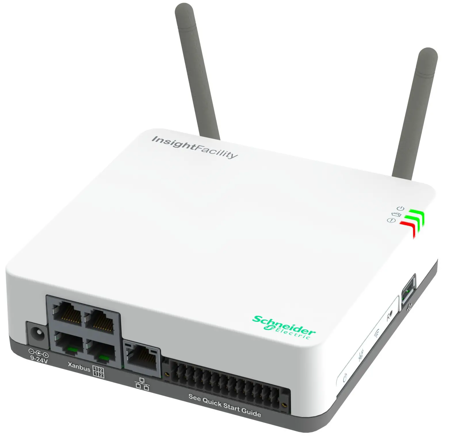
Physical Features
| 1 | 1st pair Xanbus ports |
| 2 | 2nd pair Xanbus ports |
| 3 | Ethernet port |
| 4 | Antenna |
| 5 | 26-pin port (see 26-Pin Connector Pinouts) |
| 6 | Connector Pinouts) |
| 7 | LED indicators |
| 8 | Wi-Fi button |
| 9 | Settings button |
| 10 | Power button |
| 11 | Power port(detachable) |
| 12 | DIN rail clip |
| 13 | Reset pinhole button |
| 14 | USB port |
LED Indicators

| Icon | Color | LED | Description |
| Green | Power | The InsightFacility is powered on. | |
| Green | Memory | The device is logging data to internal memory when flashing. | |
| Red | Event | Devices on the Power system have events to report. |
Microsoft, Windows, and Internet Explorer are owned by Microsoft. Chrome is owned by Google.
Safari and Mac OS are trademarks of Apple Inc. All other trademarks are owned by Schneider Electric Industries SAS or its affiliated companies.
26-Pin Connector Pinouts
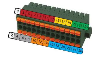
| PIN | Description of the bottom row | PIN | Description of the top row |
| 2 | 9–24VDC power input | 1 | GND |
| 4 | GND | 3 | 0–10VDC analog input 1 |
| 6 | 12VDC digital input 1 | 5 | 0–10VDC analog input 2 |
| 8 | 12VDC digital input 2 | 7 | GND |
| 10 | ISO1 CAN GND | 9 | 4–20mA input 1 |
| 12 | ISO1 CAN L | 11 | 4–20mA input 2 |
| 14 | ISO1 CAN H | 13 | GND |
| 16 | ISO2 RS485 GND | 15 | Relay 1 NO |
| 18 | ISO2 RS485 1A | 17 | Relay 1 COM |
| 20 | ISO2 RS485 1B | 19 | Relay 1 NC |
| 22 | ISO2 RS485 GND | 21 | Relay 2 NO |
| 24 | ISO2 RS485 2A | 23 | Relay 2 COM |
| 26 | ISO2 RS485 2B | 25 | Relay 2 NC |
* These pins are currently reserved for future functionality, check sesolar.com for updates.
NOTE: Pin wire size 16–24 AWG
Choosing a Location
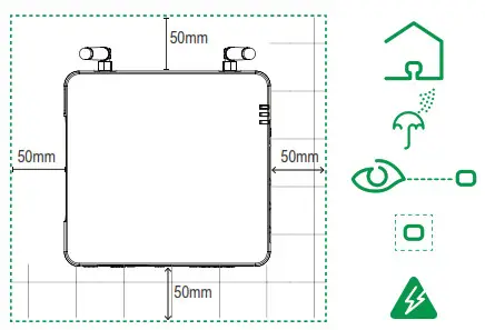
- You should not run cables through conduits that can be exposed to lightning strikes. The following are recommended maximum cable lengths in an InsightFacility system: l 131 feet (40 m) Total Xanbus network l 328 feet (100 m) Router to InsightFacility l 164 feet (50 m) Modbus Master (RS 485) to InsightFacility
- Choose a clean, dry, easily accessible location indoors.
- If you mount the InsightFacility on a wall, the recommended height is at eye level so that you can clearly see the LED indicators and have easy access to the data and communication ports.
- All of the ports on InsightFacility are accessible from the sides of the device when mounted on a wall or DIN rail. Clearance of at least 2 inches (50 mm) around the device is needed to allow for the bending radius of cables that connect to the InsightFacility.
Mounting the InsightFacility
- Use a standard 35-mm “top hat” DIN rail (EN50022).
- You may choose to move the mounting clip to the side as shown.
- Attach the InsightFacility to the DIN rail. Hook the bottom catch of the clip onto the rail, pull up a little to retract the bottom catch and hook the top catch of the clip onto the rail.
- Connect the wiring and cables.

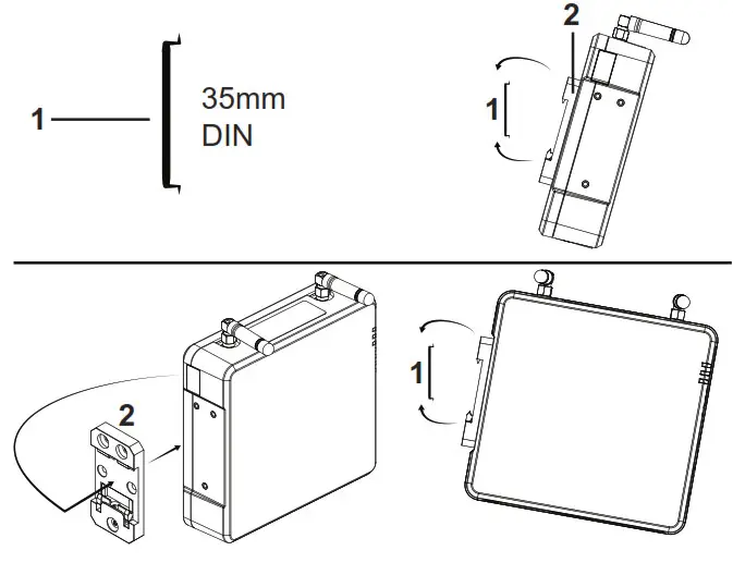
| Item | |
| 1 | DIN rail (EN50022) |
| 2 | Mounting clip (detachable) |
Connecting the InsightFacility to the Xanbus Network
- Connect the InsightFacility to the Xanbus network using daisy chain configuration.
- Xanbus components can be arranged in any order.
- Use a network terminator at both ends of the network. Do not connect two end devices together to form a closed-loop configuration. See illustration in the next column.
- Do not interconnect two separate Xanbus networks, meaning, do not daisy chain one Xanbus network with another. Use only one pair of Xanbus ports for the daisy chain. If you only have one Xanbus network use Xanbus 1. If you have two separate Xanbus networks connect the second network to Xanbus 2. See Figure 1 for Xanbus 1 pair of ports – one top and one bottom.
NOTICE
EQUIPMENT DAMAGE
- Do not connect a Xanbus cable plug into the Ethernet port on the InsightFacility.
- Connect only to Xanbus ports and use the network terminators to each end device in the daisy chain.
Failure to follow these instructions can result in equipment damage.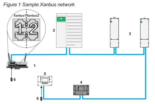
NOTE: This Xanbus 1 network is for illustration purposes only.
| 1 | InsightFacility unit | 4 | Conext AGS (automatic generator start) |
| 2 | Conext XW Pro | 5 | Conext SCP (system control panel) |
| 3 | MPPT 80 600 | 6 | Network terminators |
Connecting the InsightFacility to the Internet
Before connecting a computer and router to InsightFacility, make sure it meets the following prerequisites.
- Microsoft® Windows® 7 or later, Mac OS® X 10.4.8. or later
- Internet Explorer® 11.476 or later, Google Chrome™ 78.x or later, Safari® 5.x or later
- JavaScript and cookies must be enabled in your web browser.
- Router – the network router must be able to supply DHCP addresses automatically to connected devices. If your network router does not support automatic DHCP, refer to your network router’s user guide or contact your system administrator.
NOTICE
EQUIPMENT DAMAGE
- For a complete list of prerequisites, see the Owner’s Guide.
- Do not connect an Ethernet cable from the InsightFacility to the MODEM port on the network router.
- Do not connect an Ethernet cable plug into a Xanbus port on the InsightFacility.
Failure to follow these instructions can result in equipment damage.
- Make sure the computer and network router are turned on and the InsightFacility is not turned on. Make sure the network router selected has DHCP enabled.
- Connect an Ethernet cable between the computer’s network port and a LAN port on the router.
- Connect an Ethernet cable between a LAN port on the router and the Ethernet port on InsightFacility.

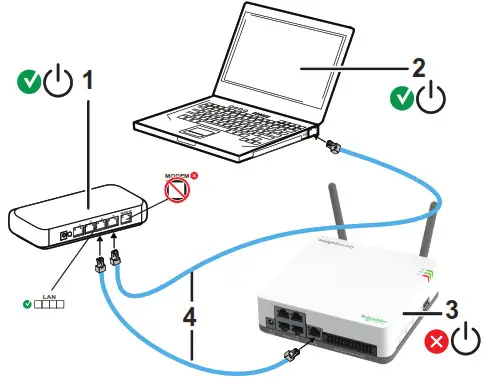
| Item | |
| 1 | router/modem |
| 2 | laptop |
| 3 | InsightFacility unit |
| 4 | Ethernet cables |
Turning the InsightFacility On (or Off)
Before turning on the InsightFacility, you must connect it to a power source – either:
- by using the (A) AC/DC adapter,
- by connecting it to a (B) Xanbus network, or
- by connecting a (C) 26-pin connector to the 26-pin terminal block.

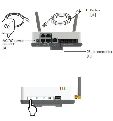
NOTE: An external power supply is not needed if the InsightFacility is connected to a Conext XW+ inverter, Conext XW Pro inverter, MPPT-80, or MPPT-100 devices.
- Select a power source (A), (B), or (C).
- Connect (A), (B), or (C)’s connector to InsightFacility’s Power port for (A), Xanbus port for (B), or terminal block for (C), respectively.
- Connect (A)’s power plug to an AC wall outlet, connect (B)’s other Xanbus cable connector to a Xanbus port on a Xanbus device or connect (C)’s pins 1 & 2 to an energy-limited DC source (9–24VDC).
- Observe the LED indicators and wait for the Power LED to light up steadily. The InsightFacility is now turned on.
- Proceed to login to the InsightFacility Web Application.
- Press the Power button to shut down the unit and turn it off.
NOTE: In the 26-pin connector, pin 1 connects to a 9-24VDC source and pin 2 connects to GND. See 26-Pin Connector Pinouts.
Logging in to the InsightFacility Web Application
- If you have connected the InsightFacility via Wi-Fi Access Point, go to the IP address https://192.168.100.1 to access the web user interface.
- If you have connected the InsightFacility via Ethernet or Wi-Fi Station, use the following steps:
a. Insert a blank USB drive into the InsightFacility USB port.
Ensure there are no firmware upgrade files on this USB drive.
b. After the InsightFacility beeps twice, remove the USB drive.
c. Insert the USB drive into your laptop USB port.
d. Copy the HTML file to your laptop.
e. Remove the USB drive from your laptop.
f. Open the HTML file and click the link to the IP address of InsightFacility. - Bookmark this address. Important: The web address is a locally and privately assigned (LAN) device address that is also protected by a firewall.
- Select your User Name. Select Admin.
NOTE: A maximum of two Admin users can be logged in to one InsightFacility at the same time. For more information, see InsightFacility Owner’s Guide (document number: 990-91411). - Enter your Password. The initial password is Admin123.
- Important: When prompted, change the initial password immediately to protect the device from unauthorized users and to enable changes to devise settings.
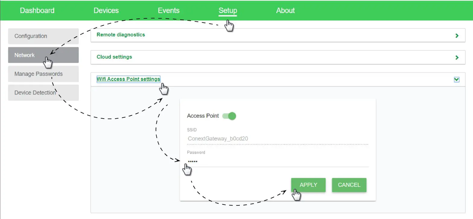
NOTE: To perform adminstrative functions such as a firmware update, set User Name to Admin. Settings are disabled until the initial password is changed. - Change the InsightFacility SSID and network password:
a. Go to Setup > Network > Wifi Access Point Settings
b. (Optional) Replace the current Wi-Fi network name under the SSID field with an appropriate name. You are limited to 64 alphanumeric characters including symbols.
c. Replace the current password under the Password field with 10 or more alphanumeric characters including symbols.
d. Click Apply to save the new password and/or SSID.
Installing Upgrades Remotely
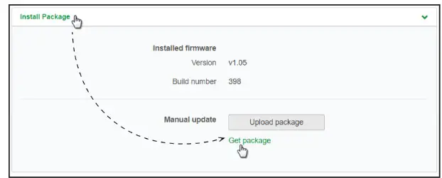
- From the InsightFacility Web Application home page, go to Setup > Configuration > Install Package.

- Download the firmware package.
a. Click Get package. This will take you to the InsightFacility product webpage.
b. From the product webpage, go to DOWNLOADS > Firmware.
c. Search for the latest firmware package from the list and click it to begin downloading.
d. Save the .epkg file to a local directory. - Go back to the InsightFacility Web Application.
- Click Upload Package.
- Search and select the firmware package (.epkg file) you saved in a local directory from the InsightFacility product webpage.
- Click Open from the Windows dialog. The upgrade begins automatically.
- As the firmware package is transferred to InsightFacility, progress is indicated in percentage, and a message screen indicates when the file transfer has been completed successfully.
- When prompted, reboot the InsightFacility.
Using the InsightFacility Web App via Wi-Fi Access Point (AP)
NOTE: This procedure is not about connecting to a local area network (LAN) via Wi-Fi. In order to establish a user interface with InsightFacility, a direct Wi-Fi connection is necessary. The following are the pre-requisites:
- Laptop with Microsoft® Windows® 7 or later, Mac OS® X 10.4.8. or later
- Wi-Fi setting for the laptop is enabled
- Web browser such as Google Chrome™ 78.x or later, Microsoft® Windows® Internet Explorer® 11.476 or later, Safari® 5.x or later
- JavaScript and cookies must be enabled in your web browser.
- Make sure the laptop and InsightFacility are turned on.
- Enable Wi-Fi on the laptop, if not already.
- Open Wi-Fi Settings, then look for and connect to the InsightFacility SSID. For example, you may look for something similar to InsightFacility_xxxxxx
- Enter the password when prompted.
NOTE: The password is printed on a label on the back panel of the InsightFacility unit. - Proceed to Log in to the InsightFacility Web Application.

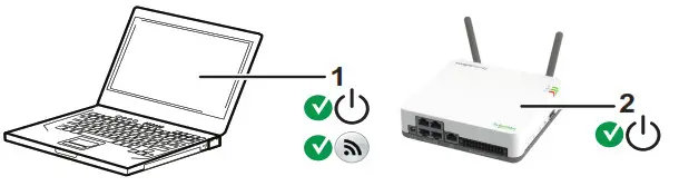
| 1 | Laptop |
| 2 | InsightFacility unit. Wi-Fi password label is on the back panel. |
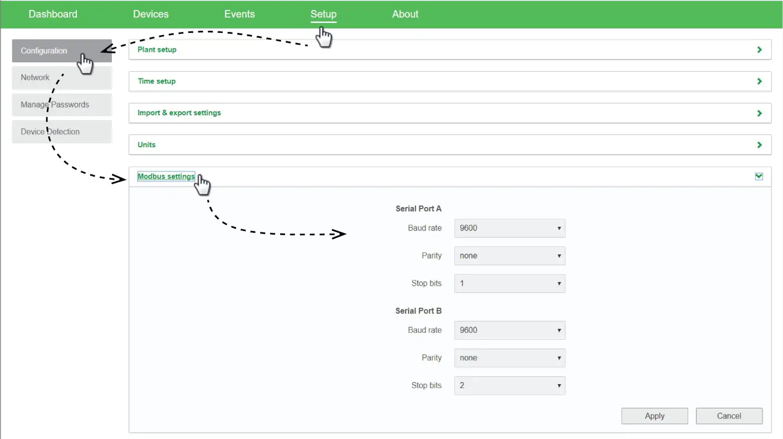
Connecting and Configuring Modbus Devices
NOTE: For Modbus map information, contact Schneider Electric.
Connect Modbus wires to pins 16, 18, and 20 (see 26-Pin Connector Pinouts), and then complete the following steps in the InsightFacility web application:
- Go to Setup > Configuration > Modbus Settings.
- Complete the Serial Port setup and then click Apply.

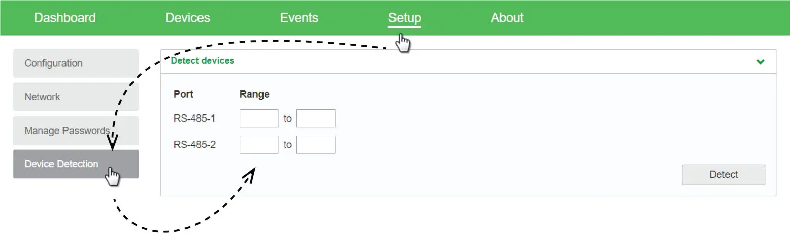
- Go to Home > Setup > Device Detection.
- Under Range, enter a Modbus address range and then click Detect.

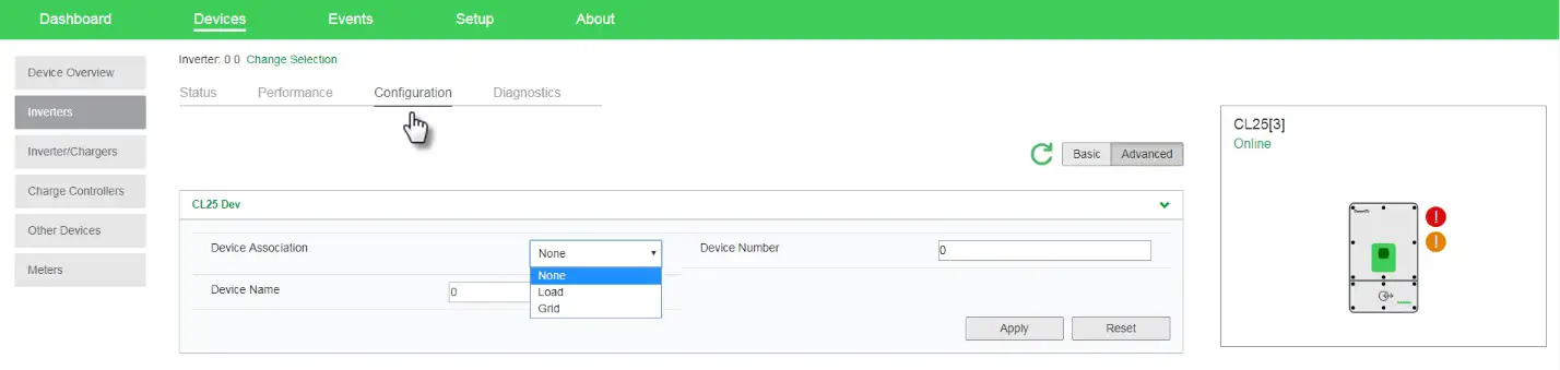
- Go to Devices and then select a device.
- Go to Configuration and configure the device. Repeat steps 5 and 6 for each device.

FCC Compliance
This device complies with Part 15 of the FCC Rules. Operation is subject to the following two conditions: (1) this device may not cause harmful interference, and (2) this device must accept any interference received, including interference that may cause undesired operation.
Electrical Specifications
NOTE: Specifications are subject to change without prior notice.
NOTICE
EQUIPMENT DAMAGE
Do not power the unit without first installing the supplied antennas.
Failure to follow these instructions can result in equipment damage.
| Power Consumption | 2 W average / 10 W peak |
| AC/DC adapter | Input 100-240 V AC, 50-60 Hz, 0.48 A, Output: 12 V DC, 1.6 A, 5.5 mm outer, 2.1 mm center-positive jack. NOTE: Required when used with the Conext SW. |
| Xanbus | When connected to Conext XW ProD<W+ or MPPT 80 600 providing network power |
| 9-24V on 26-pin connector | 9-24 V DC, 1 A max input only through pins 1 and 2 Accepts 16-24 AWG pin wire size, wire length should meet local regulations |
| Operation Frequency | 2412-2472 MHz (Europe) 2414-2462 MHz (N. America) |
| Max. radio frequency power transmitted | 17.06 dBm (E.I.R.P., Declaration for EU) |
Physical Specifications
| Weight (device only) | 330 g (0.73 lb) |
| P rating /Mounting Location | IP 20, NEMA 1, Indoor only |
| Status Display | 3 x LEDs |
| Temperature | Operating: -4 to 122 °F (-20 to 50 °C) Storage: -40 to 185 °F (-40 to 85 °C) Maximum case temperature: 140 °F (60 °C) |
| Humidity | Operating: < 95%, non-condensing Storage: < 95% |
Regulatory
| EMC immunity | EN61000-6-1 EN 55035 EN 301 489-1, -17 |
| EMC emissions | EN61000-6-3 EN 55032 EN 301 489-1, -17 FCC part 15B ICES-003 |
| Substances / environmental | RoHS |
| FCC ID | Contains 2AODL-CONEXTGTWY |
| IC ID | Contains 24209-CONEXTGTWY |
| Model number | 865-0329 |
Features
| Programmable dry contact relay | Screw 3-terminal, 16-24 AWG, NC-Com-NO, Form: Class 2,24 V DC, 4 A max SELV input only |
| Web-based user interface | Internet Browser |
| Remote firmware upgrades | Yes (InsightFacility and connected Xanbus devices) |
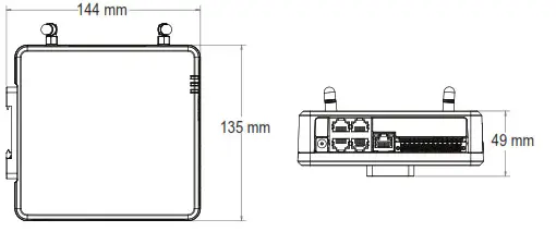
Dimensions
Copyright © 2020 Schneider Electric. All Rights Reserved.
990-91409
August 2020


