brother cv ql800 High-speed, Professional Label Printer
The Brother logo is a registered trademark of Brother Industries, Ltd. Brother is a registered trademark of Brother Industries, Ltd. © 201 6 Brother Industries, Ltd. All rights reserved.
Microsoft and Windows are registered trademarks of Microsoft Corporation in the United States and other countries. Each owner whose software title is mentioned in this document has a Software License Agreement specific to its proprietary y programs. Any trade names and product names of companies appearing on Brother products, related documents and any other materials are all trademarks or registered trademarks of those respective companies.
IM PORTANT PLEASE READ CAREFULLY
Note
- This documentation (“Documentation”) provides information that will assist you in controlling your Printer
- QL XXX (where XXX is the model name)
- You may use the Documentation only if you first agree to the following conditions.
- If you do not agree to the following conditions, you may not use the Documentation.
Condition of Use
You may use and reproduce the Documentation to the extent necessary for your own use of your Printer Model (“Purpose”). Unless expressly permitted in the Documentation, you may not;
- copy or reproduce the Documentation for any purpose other than the Purpose,
- modify, translate or adapt the Documentation, and/or redistribute it to any third party
- rent or lease the Documentation to any third party, or,
- remove or alter any copyright notices or proprietary rights legends included within the Documentation.
No Warranty
- Any updates, upgrades or alteration of the Documentation or Printer Model will be performed at the sole discretion of Brother. Brother may not respond to any re quest or inquiry about the Documentation.
- THIS DOCUMENTATION IS PROVIDED TO YOU “AS IS” WITHOUT WARRANTY OF ANY KIND, WHETHER EXPRESS OR IMPLIED, INCLUDING, BUT NOT LIMITED TO, THE IMPLIED WARRANTY OF FITNESS FOR A PARTICULAR PURPOSE. BROTHER DOES NOT REPRESENT OR WARRANT THAT THIS DOCUMENTATION IS FREE FROM ERRORS OR DEFECTS.
- IN NO EVENT SHALL BROTHER BE LIABLE FOR ANY DIRECT, INDIRECT, PUNITIVE, INCIDENTAL, SPECIAL OR CONSEQUENTIAL DAMAGES OR ANY DAMAGES WHATSOEVER, ARISING OUT OF THE USE, INABIL ITY TO USE, OR THE RESULTS OF USE OF THE DOCUMENTATION OR ANY SOFTWARE PROGRAM OR APPLICATION YOU DEVELOPED IN ACCORDANCE WITH THE DOCUMENTATION.
Introduction
This material provides the necessary information for directly controlling the Brother printer QL-XXX (where “XXX” is the model name). This information is provided assuming that the user has full understanding of the operating system being used and basic mastery of USB and networks in a developer’s environment.
Details concerning the USB interface are not described in this material. If a USB interface is being used, refer to “Appendix A: USB Specifications” to prepare the interface.
Read the model names that appear in the screens in this manual as the name of your printer.
About Raster Commands
Using raster commands a QL-XXX printer (where “XXX” is the model name) can be used to print without using our printer driver.
This operation is useful in the following situations.
- When printing from an operating system other than Windows (Example: When printing from a Linux computer or mobile terminal)
- When adding print functions to an existing system
In addition, printing can be performed with advanced settings In this material, “raster” refers to binary bitmap data (collection of dots). Refer to this material to print by sending initialization commands and control codes together with raster data to the QL-XXX printer (hereafter, referred to as “printer”). This manual describes the procedure for adding these codes and sending the data.
Printing Using Raster Commands
The printing procedure is described below. For detailed flow charts, refer to “5. Flow Charts”. For details on each command, refer to “4. Printing Command Details”.
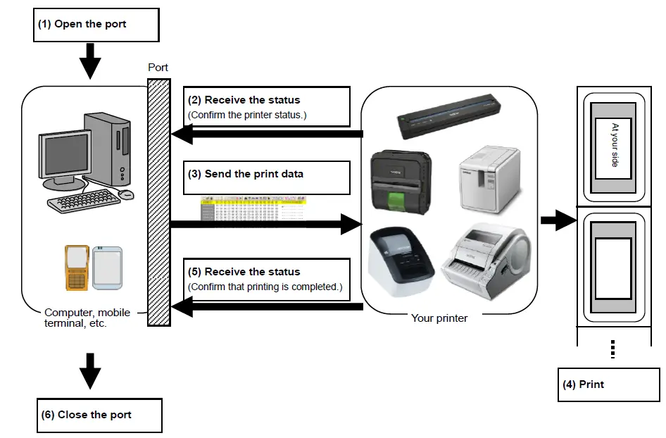
- Open the USB/ serial/ network port Open the USB/serial/network port in the operating environment. The procedure for opening the US B/serial/network port is not described in this material.
- Confirm the printer status sent from the printer The “status information request” command is sent to the printer, the status information received from the printer is analyzed, and then the status of the printer is determined. For details on the “ status information request” command and on the definition s of “status”, refer to “ Status information request” in “ 4 . Printing Command Details
- Send the print data If the status analysis confirms that media compatible with the print data is loaded into the printer and that no error has occurred, the print data is sent. The structure of the print data is explained in the next section, “ 2 . Print Data
Note: No command can be sent to the printer after the print data is transmitted and until the completion of printing is confirmed. Even the “ status information request” command cannot be sent during printing. - Print the data
- Confirm that printing is completed When printing is completed, the status is received from the printer. If t his status is analyzed to confirm that printing is completed, printing one page is considered finished. If the print job has multiple pages, 2 through 4 are repeated.
- Close the USB/ serial/ network port After all printing is finished, close the USB/serial/network port.
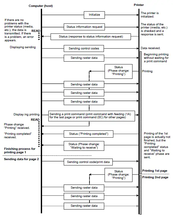
Note: In order to print at high speed when a USB port is use d to send uncompressed raster data, the Brother QL X XX starts printing when it starts to receive print data, instead of waiting for a print command (concurrent printing). For the processing flow, for example when managing errors, refer to “ 5 . Flow Charts
Print Data
Print data overview
The print data is constructed of the following: 1 initialization commands , 2 control codes , 3 raster data, and 4 p rant command s . If the print job consists of multiple pages, 2 through 4 are repeated.
- Initialization commands Specified only once at the beginning of the job.
Sequence Command Name Description/Example 1 Invalidate Sends a 400-byte invalidate command, and then resets the printer to the receiving state. 2 Initialize Initializes for printing. 1Bh, 40h (Fixed) - Control codes
Added at the beginning of each page and sent for each page.Sequence Command Name Description/Example 1 Switch dynamic command mode Switches to raster mode. 1Bh, 69h, 61h, 01h 2 Switch automatic status notification mode Dynamically switches whether an automatic status notification is given during printing.
1Bh, 69h, 21h, 00h3 Print information command Sets the print information for the printer. For 102-mm-wide continuous length tape:
1Bh, 69h, 7Ah, 86h, 0Ah, 66h, 00h, 09h, 07h, 00h, 00h, 00h, 00h4 Various mode To select “Auto Cut” 1Bh, 69h, 4Dh, 40h 5 Specify the page number in “cut each * labels”
When an auto cut setting is effective, specify the number of sheets for auto cut. For each sheets,
1Bh, 69h, 41h, 01h
6 Expanded mode To select “Cut at End” flag 1Bh, 69h, 4Bh, 08h 7
Specify margin amount
Specifies the amount of the margins. For 3 mm margins: 1Bh, 69h , 64h, 23h, 00h
8 Select compression Selects the compression mode for raster graphics. mode To send the data compressed to TIFF format: 4Dh, 02h - Raster data
Repeated for each page in the print job.Sequence Command Name Description/Example – Raster graphics transfer Sends image data as commands. – Two-color raster graphics transfer Sends image data as commands for red-black printing. – Zero raster graphics Sends image data for 1 blank line as a compression command. (Valid only when TIFF is selected as the compression mode) 5Ah (Fixed) - Print commands
Specified at the end of the page.Sequence Command Name Description/Example – Print command Specifies at the end of a page that is not the last page. 0Ch – Print command with feeding Specifies at the end of the last page. 1Ah (Fixed)
Sample (analyzing the print data of the test page)
- Based on print data created by the printer driver, descriptions of the commands introduced in the previous chapter are provided here.
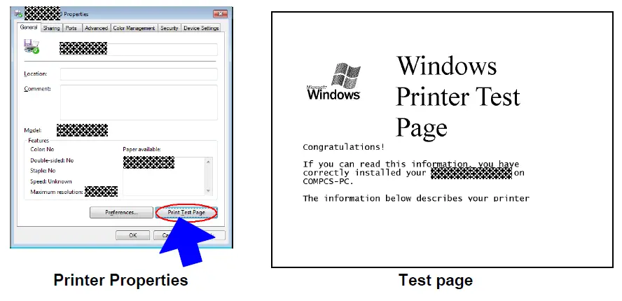
- As an example, we will check the print data created when the [Print Test Page] button in the printer Properties dialog box is clicked to print the test page.
- Since the print data differs depending on the print settings of the printer, refer to this procedure and try creating print data with various print settings.
- Furthermore, this procedure is for the Windows® 7 operating environment. A similar procedure can be performed if you are using a different operating system.
Preparation
Install the two listed below.
- Printer driver of the Brother QL-XXX
- Binary file editor
The data that we will analyze in this sample is a binary file. Therefore, use a binary file editor to display and check the contents of the binary file.
Checking the print data
The procedure for checking the print data is provided below.
- Step 1: Change the port of the printer to “FILE:”.
- Step 2: Print the desired item (in this case, the test page), and then specify the file name.
- Step 3: Open the created file in the binary file editor to check it.
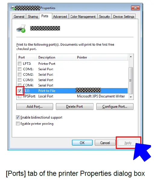
Step 1: Change the port of the printer to “FILE:”.
Open the Printers and Faxes folder, and then right-click the printer to display the Properties dialog box. In the Properties dialog box, click the [Ports] tab, select the “FILE:” check box, and then click the [Apply] button.
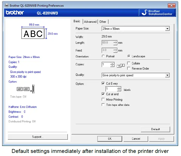
Step 2: Print the item (in this case, the test page), and then specify the file name.
For this sample, print the test page with the default print settings, which were specified immediately after the printer driver was installed.
When the test page is printed with the printer, a dialog box appears so that the file name can be specified. (Refer to the illustration below.)
After a file name is typed in and the [OK] button is clicked, the printer driver creates the print data and saves it in a file with the specified name. 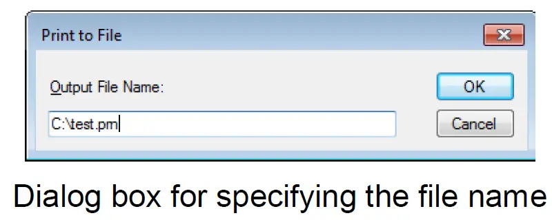
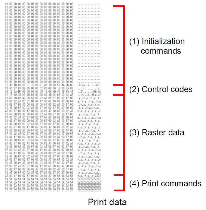
Step 3: Open the print data in the binary file editor.
Open the saved file in the binary file editor. The rows of numbers that appear are the print data. (Refer to the illustration below.) The print data is constructed of the following: (1) initialization commands, (2) control codes, (3) raster data and (4) print commands, which were described in “2.1 Print data overview”. For details on the print data, refer to “2.2.3 Explanation of print data for the test page”.
Explanation of print data for the test page
The print data for the test page outputted in the previous section is described below. The following illustration shows the print data created in section “2.2.1 Preparation” opened in the binary file editor.
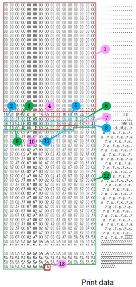
Descriptions for the numbers in the print data on the previous page are provided in the following table. For details on each command, refer to “4 . Printing Command Details
| No. | Command Name | Description |
| 1 | Invalidate | A 400-byte invalidate command is sent. |
| 2 | Initialize | The “initialize” command is sent. |
| 3 | Switch dynamic command mode | The printer is switched to raster mode. Send this command before sending raster data to the printer. |
| 4 | Switch automatic status notification mode | Dynamically switches whether an automatic status notification is given during printing. |
|
5 | Job ID setting commands | Internal specification commands Since this is a command for outputting with the commercial version driver, it is unnecessary for the user to send this command. |
| 6 | Print information command | Media size information for the print data is sent. This is the command for “1.1″ × 3.5″ (29 mm × 90 mm)” die-cut labels. |
| 7 | Various mode (1Bh+69h+4Dh+00H) | This is the command for specifying settings such as cut options. Here, “auto cut” is specified. |
| 8 | Specify the page number in “cut each * labels” | The number of pages printed before automatically cutting is specified. |
| 9 | Expanded mode | This is the command for specifying expanded functions. Here, “cut at end” is specified. |
| 10 | Specify margin amount | Since a margin amount cannot be specified with die-cut labels, this command is sent with a margin amount of 0. |
| 11 | Select compression mode | TIFF compression mode is selected. |
| 12 | Raster data | Raster data continues. |
| 13 | Print command with feeding | Since one page will be printed, this is sent at the end of the first page. |
Page data details
Resolution
| Resolution | Height-to-Width Proportion |
| 300 dpi high, 300 dpi wide | 1:1 |
| 600 dpi high, 300 dpi wide | 2:1 |
Page size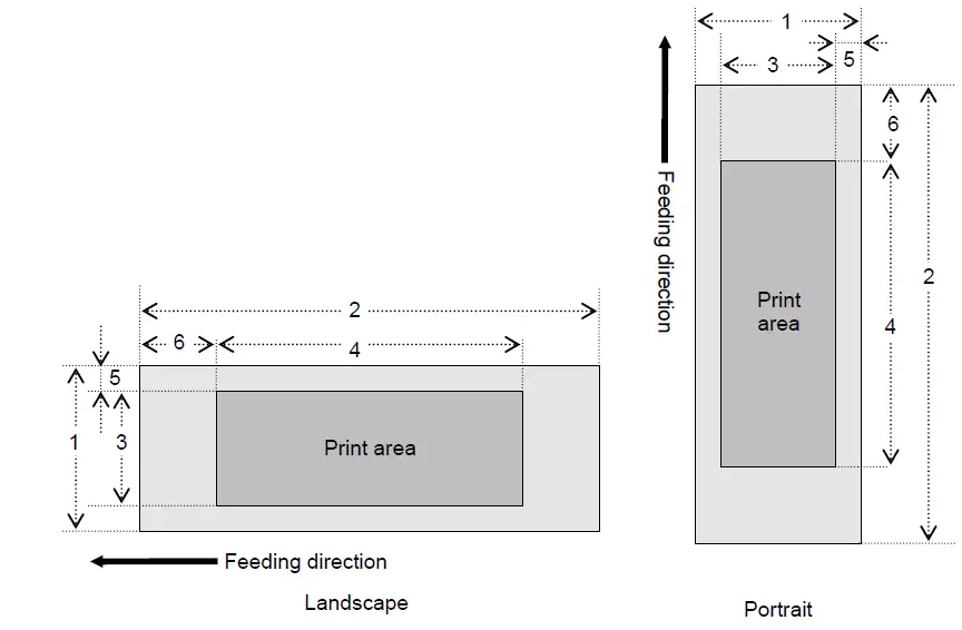
Number
- Width
- Length
- Print area width (maximum printing width)
- Print area length
- Width offset
- Length offset
| ID | Tape Size | Designation | 1 | 2 | 3 | 4 | 5 | 6 |
| 257 | 12 mm | 12 mm 0.47″ | 12.0 mm 142 dots | →2.3.4 | 9.0 mm 106 dots | →2.3.4 | 1.5 mm 18 dots | →2.3.3 |
| 258 | 29 mm | 29 mm 1.1″ | 29.0 mm 342 dots | →2.3.4 | 25.9 mm 306 dots | →2.3.4 | 1.5 mm 18 dots | →2.3.3 |
| 264 | 38mm | 38 mm 1.4″ | 38.0 mm 449 dots | →2.3.4 | 35.0 mm 413 dots | →2.3.4 | 1.5 mm 18 dots | →2.3.3 |
| 262 | 50 mm | 50 mm 1.9″ | 50.0 mm 590 dots | →2.3.4 | 46.9 mm 554 dots | →2.3.4 | 1.5 mm 18 dots | →2.3.3 |
| 261 | 54 mm | 54 mm 2.1″ | 53.8 mm 636 dots | →2.3.4 | 50.0 mm 590 dots | →2.3.4 | 1.9 mm 23 dots | →2.3.3 |
| 259 | 62 mm | 62 mm 2.4″ | 62.0 mm 732 dots | →2.3.4 | 58.9 mm 696 dots | →2.3.4 | 1.5 mm 18 dots | →2.3.3 |
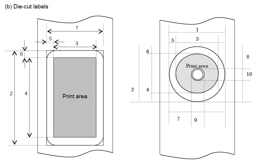
Number
- Width
- Length
- Print area width (maximum printing width)
- Print area length
- Width offset
- Length offset
- Width offset of masked area
- Length offset of masked area
- Width of masked area
- Length of masked area
| ID | Label Size | 1 | 2 | 3 | 4 | 5 | 6 |
| 269 | 17 mm x 54 mm 0.66″ x 2.1″ | 17.0 mm 201 dots | 53.9 mm 636 dots | 14.0 mm 165 dots | 47.9 mm 566 dots | 1.5 mm 18 dots | 3.0 mm 35 dots |
| 270 | 17 mm x 87 mm 0.66″ × 3.4″ | 17.0 mm 201 dots | 86.9 mm 1026 dots | 14.0 mm 165 dots | 80.9 mm 956 dots | 1.5 mm 18 dots | 3.0 mm 35 dots |
| 370 | 23 mm x 23 mm 0.9″ x 0.9″ | 23.0 mm 272 dots | 23.0 mm 272 dots | 20.0 mm 236 dots | 17.1 mm 202 dots | 1.5 mm 18 dots | 3.0 mm 35 dots |
| 358 | 29 mm × 42 mm 1.1″ x 1.6″ | 29.0 mm 342 dots | 41.9 mm 495 dots | 25.9 mm 306 dots | 36.0 mm 425 dots | 1.5 mm 18 dots | 3.0 mm 35 dots |
| 271 | 29 mm x 90 mm 1.1″ x 3.5″ | 29.0 mm 342 dots | 89.8 mm 1061 dots | 25.9 mm 306 dots | 83.9 mm 991 dots | 1.5 mm 18 dots | 3.0 mm 35 dots |
| 272 | 38 mm x 90 mm 1.4″ x 3.5″ | 38.0 mm 449 dots | 89.8 mm 1061 dots | 35.0 mm 413 dots | 83.9 mm 991 dots | 1.5 mm 18 dots | 3.0 mm 35 dots |
| 367 | 39 mm x 48 mm1 .5″ x 1.8″ | 39.0 mm 461 dots | 47.8 mm 565 dots | 36.0 mm 425 dots | 41.9 mm 495 dots | 1.5 mm 18 dots | 3.0 mm 35 dots |
| 374 | 52 mm x 29 mm 2″ x 1.1″ | 52.0 mm 614 dots | 28.9 mm 341 dots | 48.9 mm 578 dots | 22.9 mm 271 dots | 1.5 mm 18 dots | 3.0 mm 35 dots |
| 382 | 54 mm x 29 mm 2.1″ x 1.1″ | 54.0 mm 638 dots | 28.9 mm 341 dots | 51.0 mm 602 dots | 22.9 mm 271 dots | 1.5 mm 18 dots | 3.0 mm 35 dots |
| 383 | 60 mm x 86 mm 2.3″ x 3.4″ | 60.0 mm 708 dots | 86.8 mm 1024 dots | 56.9 mm 672 dots | 80.8 mm 954 dots | 1.5 mm 18 dots | 3.0 mm 35 dots |
| 274 | 62 mm x 29 mm 2.4″ x 1.1″ | 62.0 mm 732 dots | 28.9 mm 341 dots | 58.9 mm 696 dots | 22.9 mm 271 dots | 1.5 mm 18 dots | 3.0 mm 35 dots |
| 388 | 62 mm x 60 mm 2.4″ x 2.3″ | 62.0 mm 732 dots | 60.6 mm 716 dots | 58.9 mm 696 dots | 54.6 mm 645 dots | 1.5 mm 18 dots | 3.0 mm 35 dots |
| 389 | 62 mm x 75 mm 2.4″ x 2.9″ | 62.0 mm 732 dots | 75.4 mm 891 dots | 58.9 mm 696 dots | 69.4 mm 820 dots | 1.5 mm 18 dots | 3.0 mm 35 dots |
| 275 | 62 mm x 100 mm 2.4″ x 3.9″ | 62.0 mm 732 dots | 99.8 mm 1179 dots | 58.9 mm 696 dots | 93.9 mm 1109 dots | 1.5 mm 18 dots | 3.0 mm 35 dots |
| 362 | 12 mm Dia 0.47″ Dia | 12.0 mm 142 dots | 12.0 mm 142 dots | 8.0 mm 94 dots | 8.0 mm 94 dots | 2.0 mm 24 dots | 2.0 mm 24 dots |
| 363 | 24 mm Dia 0.94″ Dia | 24.0 mm 284 dots | 24.0 mm 284 dots | 20.0 mm 236 dots | 20.0 mm 236 dots | 2.0 mm 24 dots | 2.0 mm 24 dots |
| 273 | 58 mm Dia 2.2″ Dia | 58.3 mm 688 dots | 58.3 mm 688 dots | 52.3 mm 618 dots | 52.3 mm 618 dots | 3.0 mm 35 dots | 3.0 mm 35 dots |
| ID | 7 | 8 | 9 | 10 |
| 273 | 19.64 mm 201 dots | 53.9 mm 636 dots | 14.0 mm 165 dots | 47.9 mm 566 dots |
- *1 The number of dots in the table is for 300 dpi; it is difference in the high-resolution mode.
- *2 Margins of 3 mm (1.5 mm × 2) horizontally and 3 mm (1.5 mm × 2) vertically are added to a diameter of 16 mm.
Feed amount
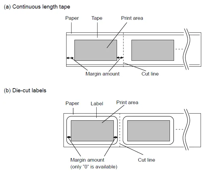
The feed amount (left and right margins) is defined below.
| Type | Minimum Margin Setting | Maximum Margin Setting |
| Continuous length tape | 3 mm 0.12″ 35 dots | 127 mm 5″ 1500 dots |
| Die-cut labels | The length offset indicated in “(b) Die-cut labels” is used. However, set “0” as the value of the “specify margin amount” command. | |
*1 The number of dots in the table is for 300 dpi; it is difference in the high-resolution mode.
Maximum and minimum lengths
The maximum and minimum lengths are defined below.
| Type | Minimum Length | Maximum Length |
| Continuous length tape | 12.7 mm 150 dots | 1000 mm 11811 dots |
| Die-cut labels | Fixed | Fixed |
*1 The number of dots in the table is for 300 dpi; it is difference in the high-resolution mode.
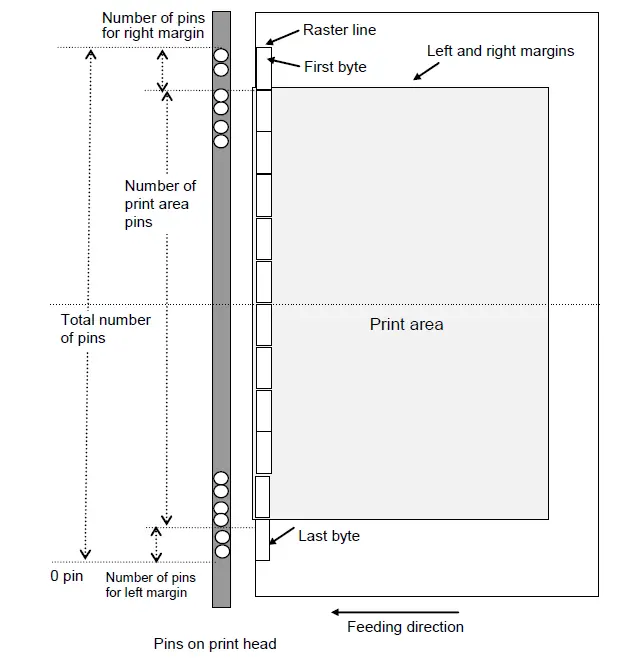
Raster line
As shown below, the parts with data to be printed are converted with “raster graphics transfer”, and the parts with no data are converted with “zero raster graphics”. On the actual tape, margins (feed) are added specified with “various mode” at the beginning and the end.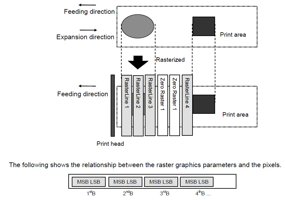
Total number of pins: 720 pins
Continuous length tape:
| Tape Size | Number of Pins for Left Margin | Number of Print Area Pins | Number of Pins for Right Margin | Number of Bytes for Raster Graphics Transfer |
| 12 mm | 585 | 106 | 29 | 90 |
| 29 mm | 408 | 306 | 6 | 90 |
| 38 mm | 295 | 413 | 12 | 90 |
| 50 mm | 154 | 554 | 12 | 90 |
| 54 mm | 130 | 590 | 0 | 90 |
| 62 mm | 12 | 696 | 12 | 90 |
Die-cut labels:
| Label Size | Number of Pins for Left Margin | Number of Print Area Pins | Number of Pins for Right Margin | Number of Bytes for Raster Graphics Transfer |
| 17mm x 54mm | 555 | 165 | 0 | 90 |
| 17mm x 87mm | 555 | 165 | 0 | 90 |
| 23mm x 23mm | 442 | 236 | 42 | 90 |
| 29mm x 42mm | 408 | 306 | 6 | 90 |
| 29mm x 90mm | 408 | 306 | 6 | 90 |
| 38mm x 90mm | 295 | 413 | 12 | 90 |
| 39mm x 48mm | 289 | 425 | 6 | 90 |
| 52mm x 29mm | 142 | 578 | 0 | 90 |
| 54mm x 29mm | 59 | 602 | 59 | 90 |
| 60mm x 86mm | 24 | 672 | 24 | 90 |
| 62mm x 29mm | 12 | 696 | 12 | 90 |
| 62mm x 100mm | 12 | 696 | 12 | 90 |
| 12mm Dia | 513 | 94 | 113 | 90 |
| 24mm Dia | 442 | 236 | 42 | 90 |
| 58mm Dia | 51 | 618 | 51 | 90 |
. Print Command List
| ASCII Code | Binary Code | Description |
| NULL | 00 | Invalidate |
| ESC i S | 1B 69 53 | Status information request |
| ESC @ | 1B 40 | Initialize |
| ESC i d | 1B 69 64 | Specify margin amount (feed amount) |
| ESC i a | 1B 69 61 | Switch dynamic command mode |
| ESC i ! | 1B 69 21 | Switch automatic status notification mode |
| Raster graphics transfer (for monochromatic printing) | ||
| w | 77 | Two-color raster graphics transfer (for two-color printing) |
| Z | 5A | Zero raster graphics |
| FF | 0C | Print command |
| Control-Z | 1A | Print command with feeding |
| ESC i z | 1B 69 7A | Print information command |
| M | 4D | Select compression mode |
| ESC i A | 1B 69 41 | Specify the page number in “cut each * labels” |
| ESC i M | 1B 69 4D | Various mode |
| ESC i K | 1B 69 4B | Expanded mode |
Printing Command Details
NULL Invalidate
- ASCII NULL
- Hexadecimal 00
Description
- Skipped
- If data transmission is to be stopped midway, send the “initialize” command after sending the invalidate ” command for the appropriate number of bytes to return to the receiving state, where the print buffer is cleared.
ESC I S Status information request
| ASCII: | ESC | i | S |
| Hexadecimal: | 1B | 69 | 53 |
Description
- When a status information request is sent to the printer, a fixed size of 32 bytes is returned as a response from the printer. For details on these 32 bytes, refer to the following
Note
Before sending print data to the printer, this command should be sent once. Since error information is automatically sent by the printer during printing, do not send this command while printing. For details on transmission of the status, refer to “5. Flow Charts
| Number | Offset | Size | Name | Value/Reference |
| 1 | 0 | 1 | Print head mark | Fixed at 80h |
| 2 | 1 | 1 | Size | Fixed at 20h |
| 3 | 2 | 1 | Reserved | Fixed at “B” (42h) |
| 4 | 3 | 1 | Series code | Fixed at “4” (34h) |
| 5 | 4 | 1 | Model code | QL-800 “8” (38h) QL-810W “9” (39h) QL-820NWB “A” (41h) |
| 6 | 5 | 1 | Reserved | Fixed at “0” (30h) |
| 7 | 6 | 1 | Reserved | Fixed at “0” (30h) |
| 8 | 7 | 1 | Reserved | Fixed at “00h” |
| 9 | 8 | 1 | Error information 1 | Refer to table (1) below. |
| 10 | 9 | 1 | Error information 2 | Refer to table (2) below. |
| 11 | 10 | 1 | Media width | Refer to table (3) below. |
| 12 | 11 | 1 | Media type | Refer to table (4) below. |
| 13 | 12 | 1 | Reserved | Fixed at 00h |
| 14 | 13 | 1 | Reserved | Fixed at 00h |
| 15 | 14 | 1 | Reserved | Fixed at 3Fh |
| 16 | 15 | 1 | Mode | Value specified where the “various mode” command 00h if not specified |
| 17 | 16 | 1 | Reserved | Fixed at 00h |
| 18 | 17 | 1 | Media length | Refer to table (3) below. |
| 19 | 18 | 1 | Status type | Refer to table (5) below. |
| 20 | 19 | 1 | Phase type | Refer to table (6) below. |
| 21 | 20 | 1 | Phase number (higher order bytes) | |
| 22 | 21 | 1 | Phase number (lower order bytes) | |
| 23 | 22 | 1 | Notification number | Refer to table (7) below. |
| 24 | 23 | 1 | Reserved | Fixed at 00h |
| 25 | 24 | 8 | Reserved | Fixed at 00h |
- Error information 1
Flag Mask Definition Bit 0 01h “No media” error Bit 1 02h “End of media” error (only for die-cut labels) Bit 2 04h Cutter jam Bit 3 08h (Not used) Bit 4 10h Printer in use Bit 5 20h Printer turned off Bit 6 40h High-voltage adapter (not used) Bit 7 80h Fan motor error (not used) - Error information 2
Flag Mask Definition Bit 0 01h “Replace media” error Bit 1 02h “Expansion buffer full” error Bit 2 04h Communication error Bit 3 08h “Communication buffer full” error (not used) Bit 4 10h “Cover open” error Bit 5 20h Cancel key (not used) Bit 6 40h Media cannot be fed
(also when the media end is detected)Bit 7 80h System error - Media width and length The media width and length is described in millimeters. 0 25 5 0 to FF h
- Continuous length tape
*Media Width: The tape width is indicated in millimeters
*Media Length: Fixed at 00hMedia Media Width Media Length 12 mm 12 0 29 mm 29 0 38 mm 38 0 50 mm 50 0 54 mm 54 0 62 mm 62 0 - Die cu labels
*Media Width: The width of the die cut section is indicated
*Media Length: The length of the die cut section is indicate dMedia Media Width Media Length 17 mm x 54 mm 17 54 17 mm × 87 mm 17 87 23 mm × 23 mm 23 23 29 mm × 42 mm 29 42 29 mm × 90 mm 29 90 38 mm × 90 mm 38 90 39 mm x 48 mm 39 48 52 mm x 29 mm 52 29 54 mm x 29 mm 54 29 60 mm x 86 mm 60 86 62 mm x 29 mm 62 29 62 mm x 100 mm 62 100 12 mm Dia 12 12 24 mm Dia 24 24 58 mm Dia 58 58
- Continuous length tape
- Media type
Media Type Value Description No media 00h Used as print information when the media type is not indicated. Continuous length tape 4Ah Used for both paper and film. Die-cut labels 4Bh Used for both paper and film. - Status type
Status Type Value Reply to status request 00h Printing completed 01h Error occurred 02h Turned off 04h Notification 05h Phase change 06h (Not used) 08h to 20h (Reserved) 21h to FFh If an error occurred during printing, the printer returns the error status.
- Phase type and phase number
If the phase number is not used, both are fixed at 00 hPhase State Phase Type Receiving state 00h Printing state 01h Receiving state
Phase Value (Dec.) Higher Order Bytes Lower Order Bytes Waiting to receive 0 00h 00h Printing state
Phase Value (Dec.) Higher Order Bytes Lower Order Bytes Printing 0 00h 00h When the printer is turned on, it is in the receiving state. When printing begins, it changes to the printing phase (phase type: printing state; phase number: printing), and the printer sends that phase stat us to the computer. When printing has finished, the printer sends the “receiving state” phase status (phase type: receiving state; phase number: waiting to receive) to the computer. Unless an error occurs during printing, the printer sends the “printing completed” status.
With concurrent printing, printing starts even if a print command has not been sent from the computer in order to print at high speed. At this time, care should be taken since the printing and waiting to receive phase statuses will be sent. ( Refer to “ 5 . Flow Charts - Notification number
Notification Value Not available 00h Cooling (started) 03h Cooling (finished) 04h
ESC@ Initialize
- ASCII: ESC @
- Hexadecimal: 1B 40
Description
- Initializes mode settings.
- Also used to cancel printing
ESC id Specify margin amount (feed amount)
- ASCII: ESC i d {n1} {n2}
- Hexadecimal: 1B 69 64 {n1} {n2}
Description
- Specifies the amount of the margins.
- Margin amount (dots)=n1+n2*256
- With die-cut labels, the margin amount at the ends of the printed area is 0.

ESC I a Switch dynamic command mode
- ASCII ESC i a {n2
- Hexadecimal 1B 69 61 {n2
Parameters
- Definition s of {n}
- 0ESC/P mode (default)
- 1Raster mode (Be sure to switch to this mode.)
- 3:Ptouch Template mode
Description
- Dynamically switches between the printer’s command modes. A printer that receives this command operates in the specified command mode until the printer is turned off.
- The printer must be switched to raster mode before raster data is sent to it. Therefore, send this command to switch the printer to raster mode.
ESC i Switch automatic status notification mode
| ASCII: | ESC | i ! | {n1} |
| Hexadecimal: | 1B | 69 21 | {n1} |
Parameters
Definitions of {n1} 0:Notify. (default) 1:Do not notify.
Description
- Dynamically switches whether the automatic status notification is given during printing. A printer that receives this command operates in the specified command mode until the printer is turned
- Use this command when building a system where the status is not obtained using a status information request.
g Raster graphics transfer
| ASCII: | g | {s} | {n} | {d1} | … {dn} |
| Hexadecimal: | 67 | {s} | {n} | {d1} | … {dn} |
Parameters
- {s} 00h
- {n} Number of bytes of raster data (d1 to dh)
However, use the following value if no compression is specified as the compression mode. n=90 - {d1~dn} Raster data.
w Two-color raster graphics transfer
| ASCII: | w | {c} | {n1} {d1} | … | {dn} |
| Hexadecimal: | 77 | {c} | {n1} {d1} | … | {dn} |
Parameters
- {s} Color No 0x01…First color data (high energy) 0x02…Second color data (low energy)
- {n1} Transfers the specified number of bytes {n1} of data.
- {d1~dn} Raster data.
Z Zero raster graphics
- ASCII Z
- Hexadecimal 5A
Description
- Fills raster line with 0
- The QL-800 does not support this
FF Print command
- ASCII FF
- Hexadecimal 0C
Description
- Used as a print command at the end of pages other than the last page when multiple pages are printed.
Control Z Print command with feeding
- ASCII Control Z
- Hexadecimal 1A
Description
- Used as a print command at the end of the last page.
ESC i z Print information command
Description
- Specifies the print information.
- Definition s of {n1} through {n10}
| {n1}: | Valid flag; Specifies which values are valid 0x02: Media type 0x04: Media width 0x08: Media length 0x40: Priority given to print quality (invalid for two-color printing) 0x80: Printer recovery always on | ||||
| {n2}: | Media type Continuous length tape: 0Ah Die-cut labels: 0Bh | ||||
| {n3}: | {n3}: Media width (mm) {n4}: Media length (mm) For the media of width 62 mm × length 100 mm, specify as n3=3Eh and n4=64h. | ||||
| {n4}: | |||||
| {n5-n8}: | Raster number = n8*256*256*256 + n7*256*256 + n6*256 + n5 If the media is not correctly loaded into the printer when the media type, media width and media length of valid flag {n1} are set to “ON”, an error status is returned. (Bit 0 of “(2) Error information 2” is set to “ON”.)* For two-color printing, the raster number is calculated as a single raster data packet using the following 186 bytes. | ||||
| ‘w’ | 02 | 90 | Second color data (90 bytes) | ||
| {n9}: | Starting page: 0 Other pages: 1 | ||||
| {n10}: | Fixed at 0 | ||||
Parameters
Definitions of {n}
| 0 | No-compression mode (Enabled) |
| 1 | Reserved (Disabled) |
| 2 | TIFF (Enabled) |
Description
- Selects the compression mode. Data compression is available only for data in raster graphic
- The QL-800 does not support the compression
[TIFF(Pack Bits)]
- 1-byte units
- If the same data is repeated, the number of data units and that 1 byte of data are
If different data is in a series, the number of data items and all of the different data are specified. - If the same data is repeated, the number of data units is specified as the actual number minus 1, expressed as a negative number.
If different data is in a series, the number of data units is specified as the number of bytes minus 1, expressed as a positive number. - If the above process results in more than 90 bytes of compressed data, the data is treated as being all different. As a result, the data will be 91 bytes, including the 1 byte that specifies the data
Example
1 raster of raster graphics transfer
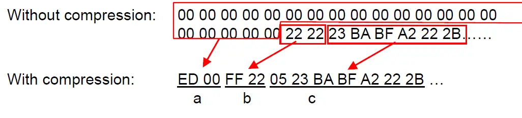
| a. | Since “00h” is repeated for 20 bytes, 20d -> 19d -> 13h changed into a negative number is EDh. Therefore: ED 00 |
| b. | Since “22h” is repeated for 2 bytes, 2d -> 1d -> 1h changed into a negative number is FFh. Therefore: FF 22 |
| c. | The following 6 bytes remain unchanged. 6d -> 5d -> 5h Therefore: 05 23 BA BF A2 22 2B |
| Continue for the remaining number of bytes for the uncompressed data. Even if 00h continues until the end, it cannot be omitted. | |
Explanation of “TIFF compression mode”
With compression, the data for the “raster graphics transfer” command is based on 90 bytes of the total number of pins (720). As shown below, with no compression, the sum of the number of offset pins and the number of pins within the print area is the byte data. However, with compression, the number of unused pins is also added to the data. In other words, with compression, this becomes 90 bytes when it is expanded by the printer, regardless of the tape width.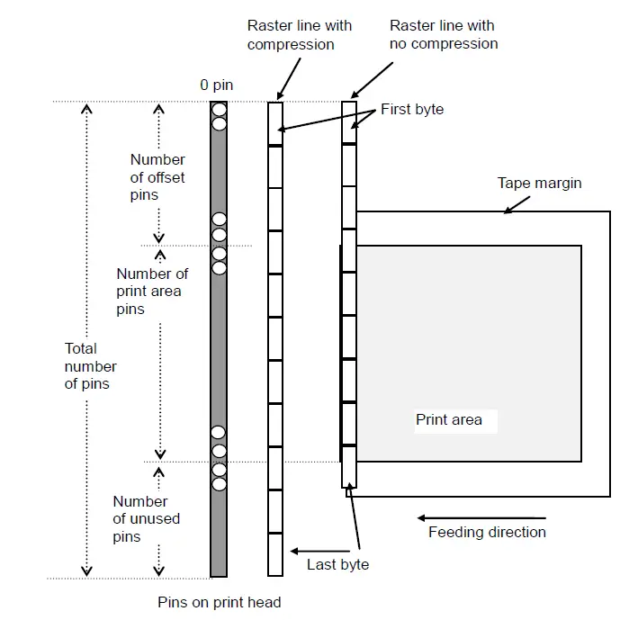
ESC i A Specify the page number in “cut each * labels”
| ASCII: | ESC | i | A | {n} |
| Hexadecimal: | 1B | 69 | 41 | {n} |
Parameters
- Definitions of {n}
- Page number = n1 (1 – 255) Default is 1 (cut each label).
Description
When “auto cut” is specified, you can specify page number (1 – 255) in “cut each * labels”.
ESC i M Various mode
| ASCII: | ESC | i | M | {n} |
| Hexadecimal: | 1B | 69 | 4D | {n} |
Parameters
Definitions of {n} The meaning of each bit in a 1-byte parameter is described below. 1 ~ 6bit: Not used 7bit: Auto cut 1: Auto cut 0:No auto cut 8bit: Not used
ESC i K Expanded mode
| ASCII: | ESC | i | K | {n} |
| Hexadecimal: | 1B | 69 | 4B | {n} |
Parameters
Definitions of {n} The meaning of each bit in a 1-byte parameter is described below. 1bit: Two-color printing 2,3bit: Not used 4bit: Cut at end 1:Cut at end (default) 0:Not cut at end 5,6bit: Not used 7bit: High resolution printing 1: It prints at 600 dpi in the paper length direction 0: It prints at 300 dpi in the paper length direction. (default) 8bit: Not used
Flow Charts
Normal flow for USB connection
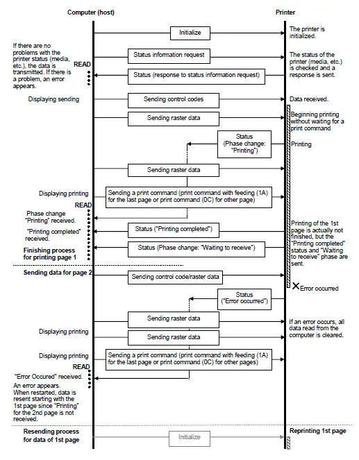
Error flow for USB connection (when feeding at the end of the page)
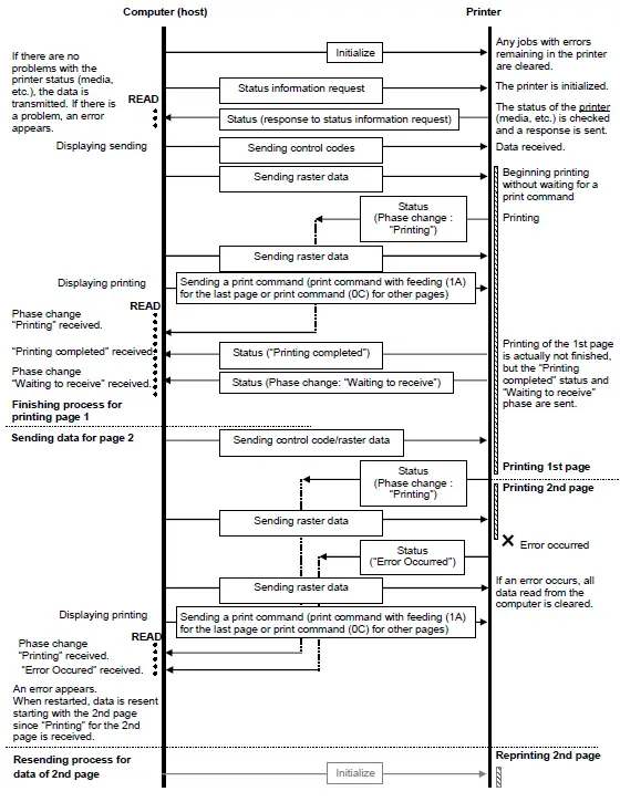
Error flow for USB connection (with a concurrent printing error such as end of tape)
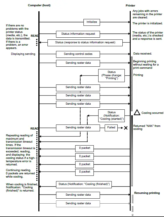
Cooling flow for USB connection
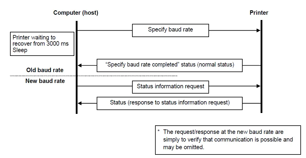
Flow for setting serial connection baud rate
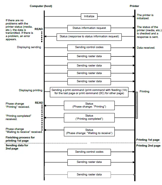
Normal flow for serial connection
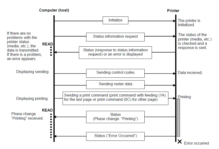
Error flow for serial connection
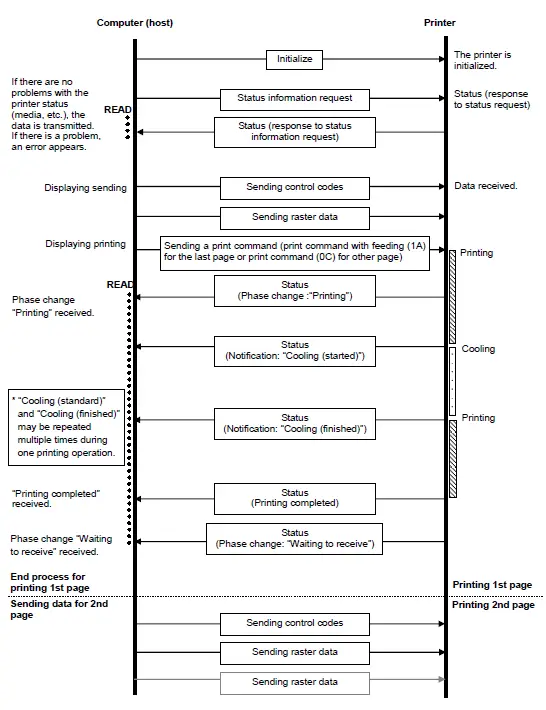
Cleaning flow for serial connection
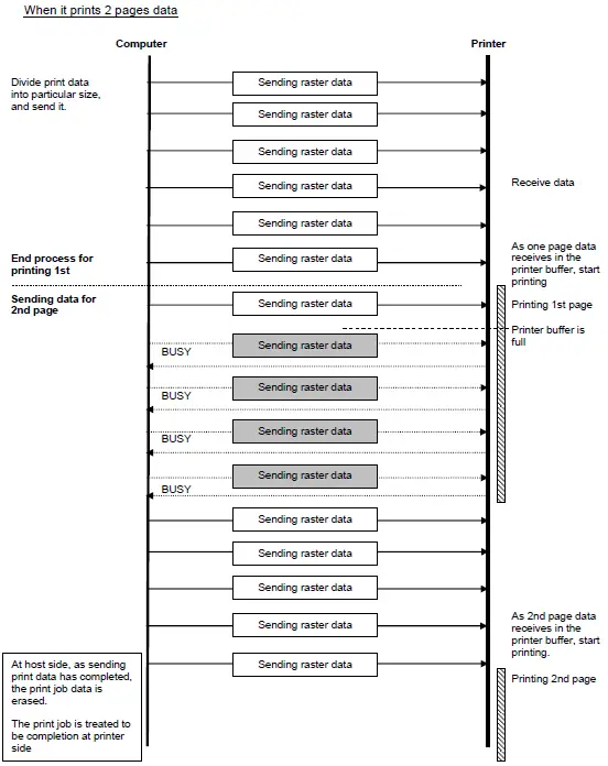
Normal Flow for Network (Standard TCP/IP port) Connection
*With a network connection, print data from the operating system’s port monitor is simply sent as is. When it prints 2 pages data
Appendix A: USB Specifications
USB specifications 1.1
| Item | Description |
| Vendor ID | 0x04F9 |
| Product ID | QL-800 : 0x209b QL-810W : 0x209c QL-820NWB : 0x209d |
| Class | Printer Mass storage |
| Character string for manufacturer | Character string descriptor: 0x01 0x0409: “Brother” |
| Character string for serial number | Character string descriptor: 0x03 0x0409: “000000000001” Last twelve digits of the printer’s serial number |
| Device speed | Full speed |
| Number of interfaces | 1 (No alternate interfaces) |
| Power supply | Self-powered |
| End point 1 | In bulk (Sends the status from the printer to the computer.) Maximum packet size: 64 bytes |
| End point 2 | Out bulk (Sends print commands and data from the computer to the printer.) Maximum packet size: 64 bytes |
Appendix B: Introducing the Brother Developer Center
Useful information for developers, such as applications, tools, SDKs as well as FAQs, are provided in the Brother Developer Center.
http://www.brother.com/product/dev/index.htm


