![]()
Shenzhen EasyDetek Technology Co., Ltd
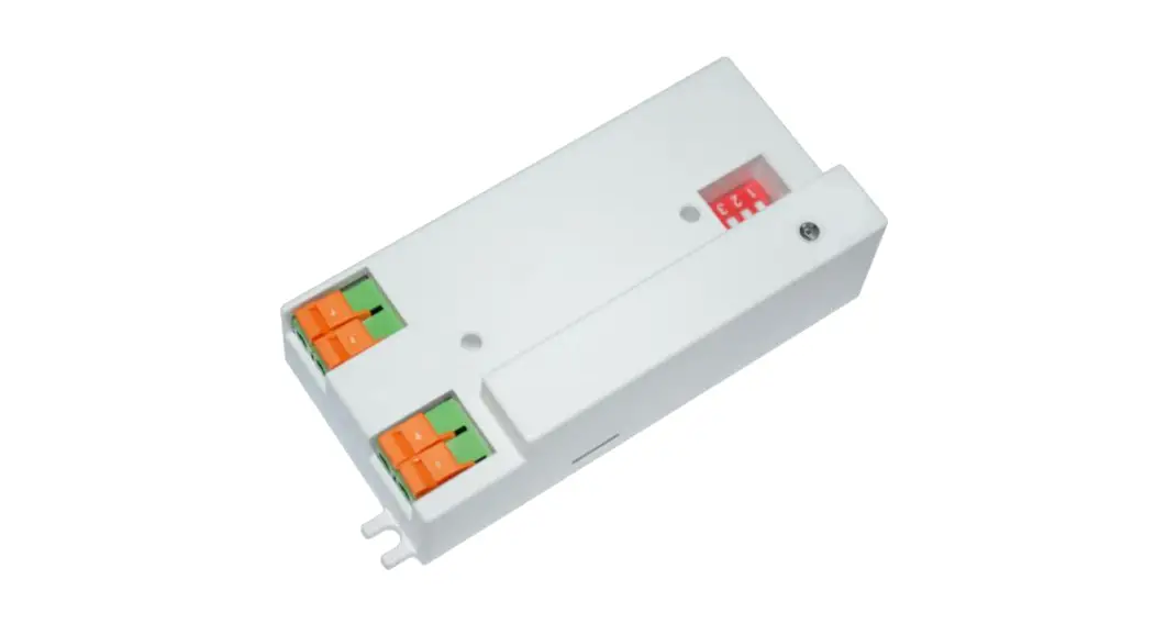
EDC212S
![]()
Product description
■ The shell is made of flame-retardant materials, with a fire rating of V-0;
■ Patented antenna design, super anti-interference; digital radar chip, good consistency;
■ Not affected by temperature, humidity, airflow, dust, noise, brightness, etc.;
■ Meet the requirements of environmental protection.
Electrical properties
| Transmit frequency | 5.8GHz±75MHz |
| Load power | <600W @100V-240V |
| Operating Voltage | AC 100-240V |
| 3db beam angle | 93°(XZ plane) 99°(YZ plane) |
| Transmission power consumption | 1mW |
| Standby power consumption | <0.5W |
| Sensing distance | 5-6m |
| Power supply frequency | 50Hz & 60Hz |
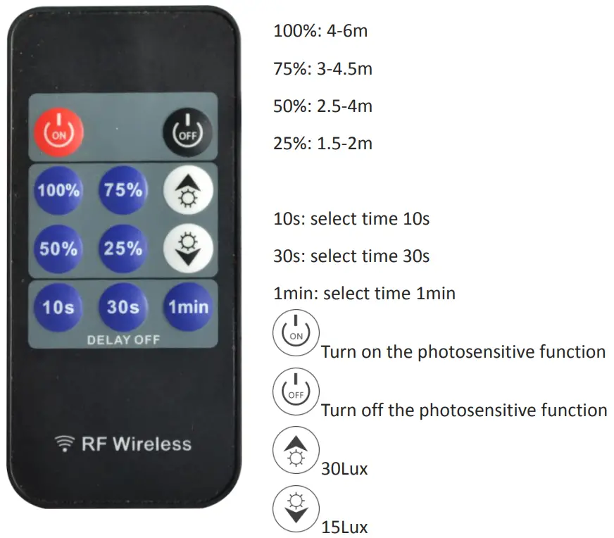
| Delay time | EDC212S-A/EDC212S-B(5s, 1min, 3min, 5min) EDC212S-C(10s, 30s, 1min) |
| Photosensitive threshold | EDC212S-A/EDC212S-B(25Lux, Disable) EDC212S-C (15Lux, 30Lux, Disable) |
| Antenna gain | 3.6dB |
| life | 50000h |
| Operating temperature | -20…﹢70℃ |
| storage temperature | -20…﹢105℃ |
Remarks:
- The test distance range is based on the module hanging height of 3m, indoor environment test, the tester’sheight is 170cm, the weight is 65-75kg, and the walking speed is 1m/s (2 steps per second). Different installation scenarios may cause range changes. Subject to actual test;
- Due to the spectral characteristics of the photosensitive device, the threshold is uniformly tested under natural light conditions;
- The delay time can be customized according to customer needs, with a delay tolerance of ±10%;\
- The switching speed interval cannot be less than 2s each time.
Typical application products
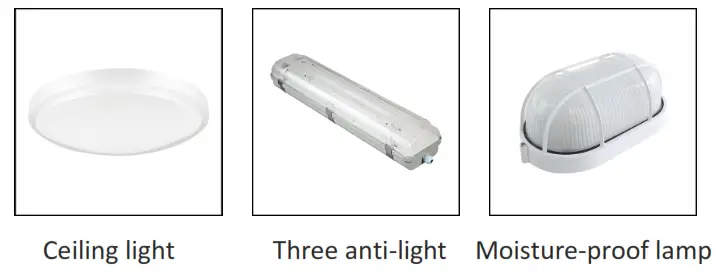
*The above are typical application products, which can be expanded to more products
Product information
| Model | Function description |
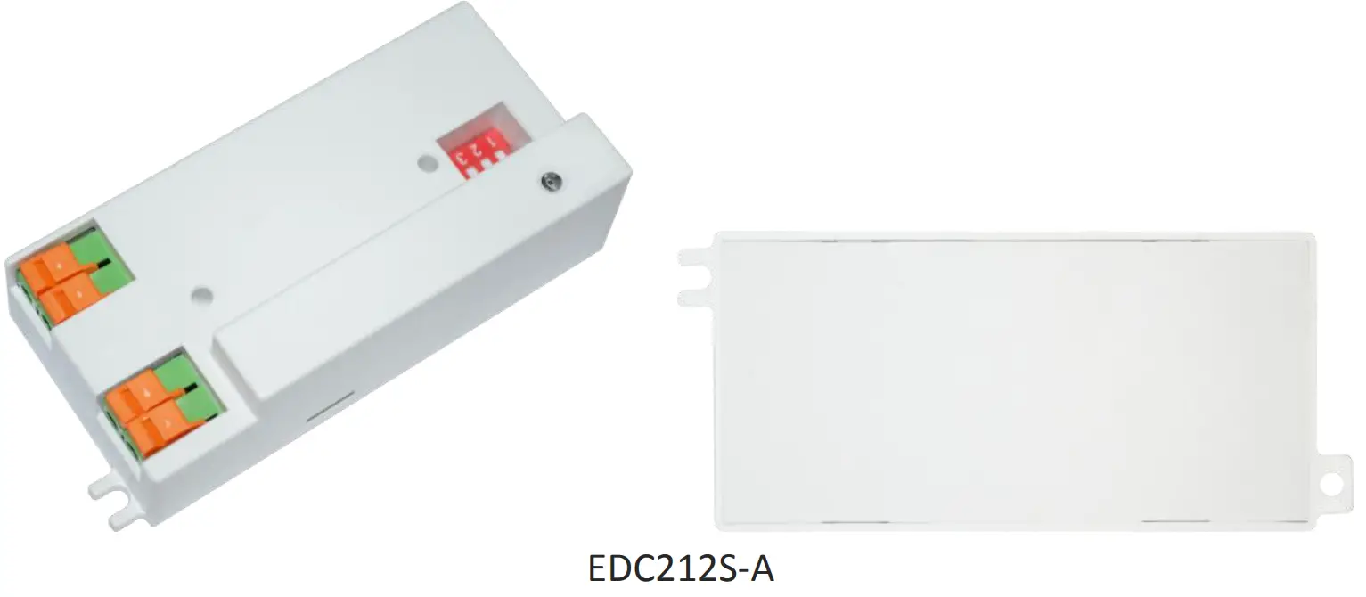
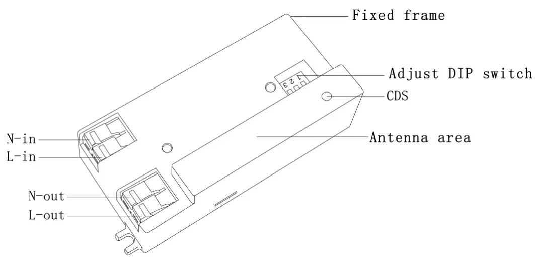
| EDC212S-A | 4-digit dialing code for forwarding installation (same side as an antenna) |
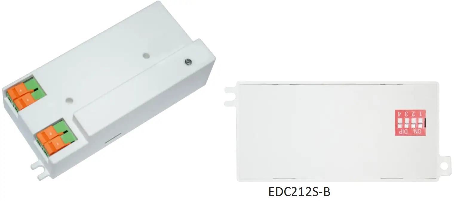
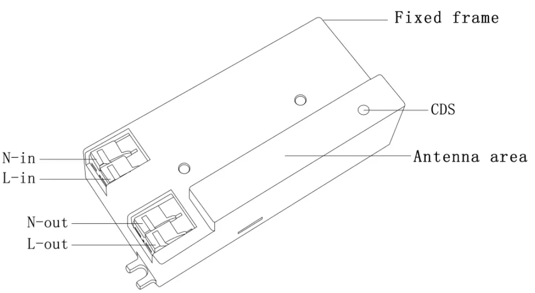
| EDC212S-B | 4 digit dialing code installed backward (on the opposite side of the antenna) |
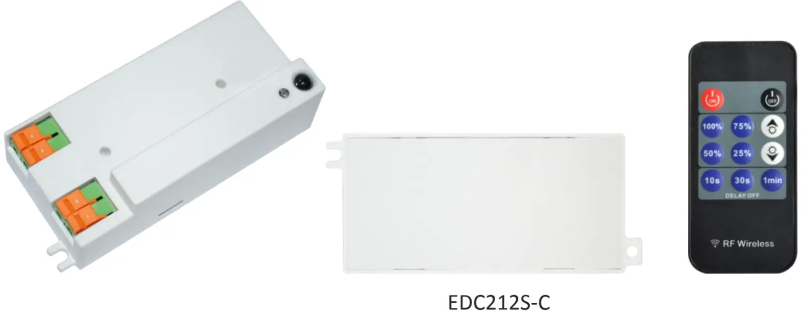
| EDC212S-C | No dial code, infrared remote control adjustment (same side as an antenna) |
DIP switch settings
| First place: Sensing distance setting | |
| 1 | |
| 100% | ON |
| 50% | – |
According to different applications, the sensing distance can be adjusted by the code switch to set 100%, 50%
| The second and third digits: delay time setting | ||
| 2 | 3 | |
| 5s | ON | ON |
| 1min | ON | – |
| 3min | – | 0N |
| 5min | – | – |
Delay time refers to the time that the light is on after the moving object leaves the sensing area. The gears can be set: 5s, 1min, 3min, 5min
| Fourth place: photosensitive threshold setting | |
| 4 | |
| 25Lux | ON |
| Disable | – |
When the ambient illuminance value is lower than the set valve, an object moves in the sensing area. The stalls are: 25Lux / all-day
Pin description
EDC212S-A pin
| Pin | Description |
| L-out | Firewire out |
| N-out | Zero line out |
| L-in | Firewire in |
| N-in | Zero line in |
EDC212S-B pin
| Pin | Description |
| L-out | Firewire out |
| N-out | Zero line out |
| L-in | Firewire in |
| N-in | Zero line in |
EDC212S-C Pin
| Pin | Description |
| L-out | Firewire out |
| N-out | Zero line out |
| L-in | Firewire in |
| N-in | Zero line in |
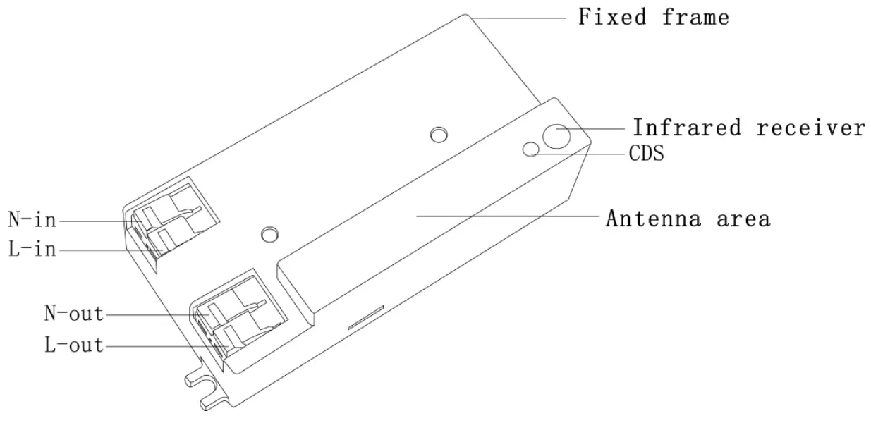
Infrared remote control settings
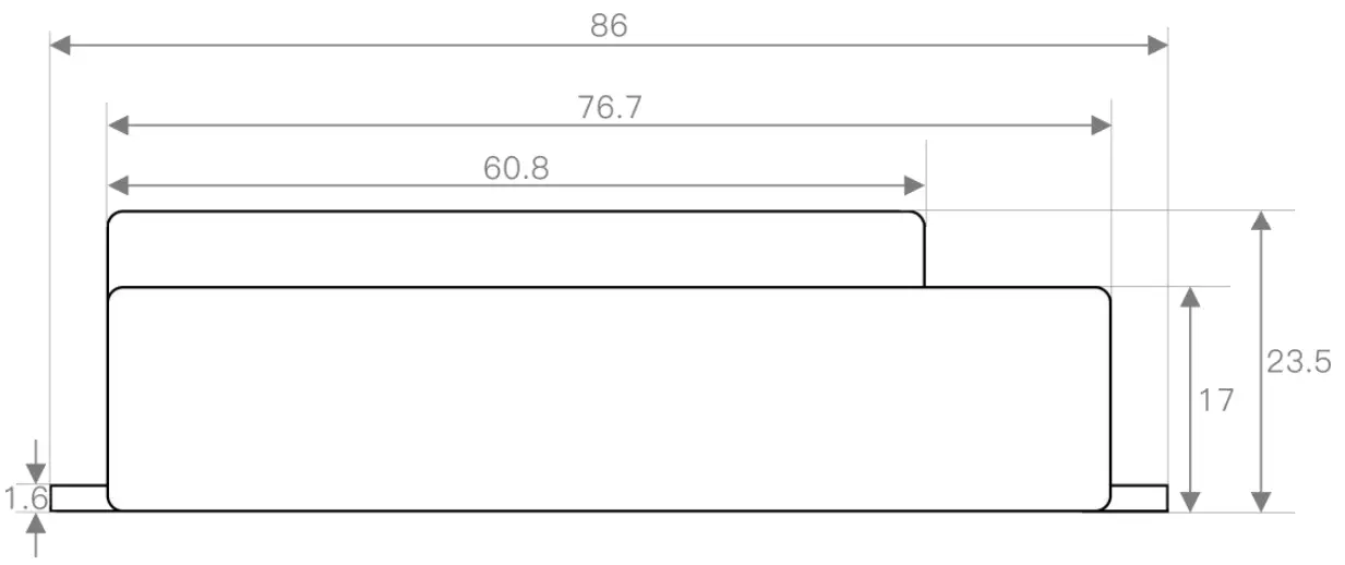
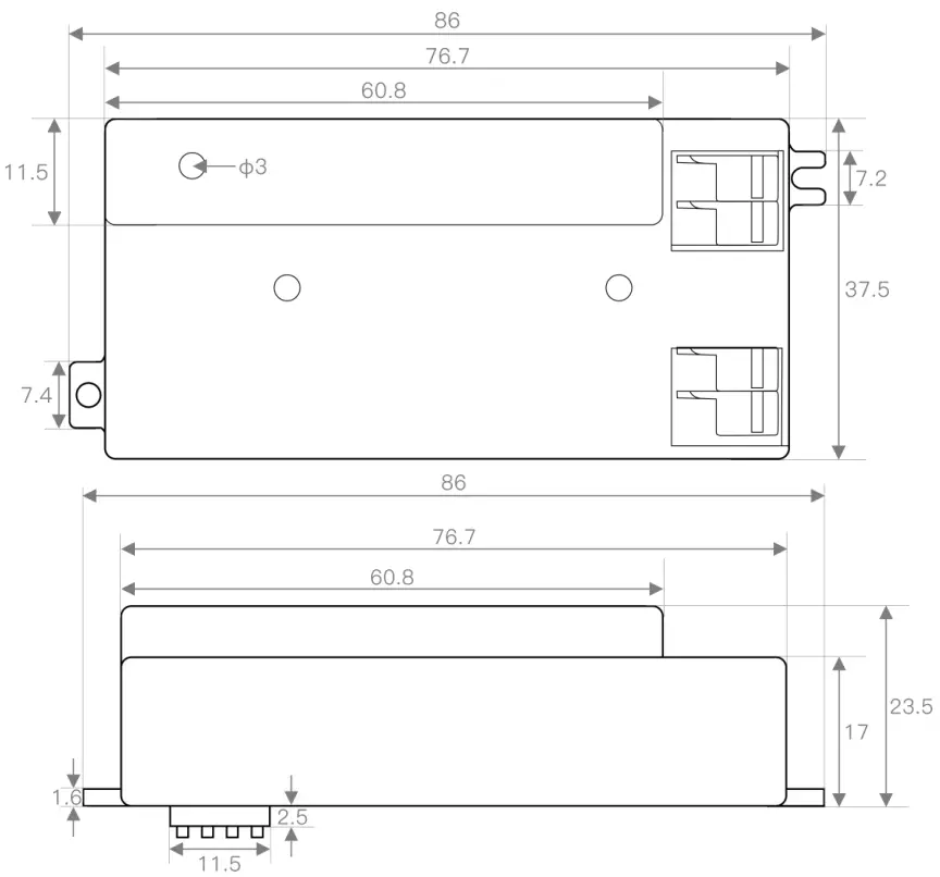
Product size chart
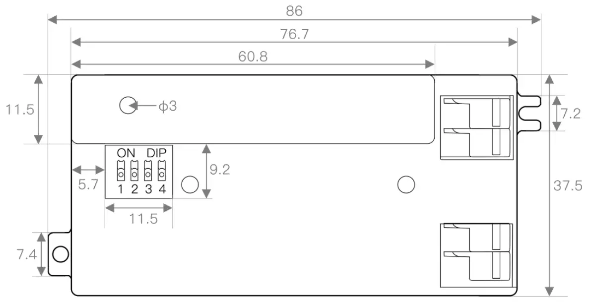
EDC212S-A Unit: (mm)
EDC212S-B Unit: (mm)
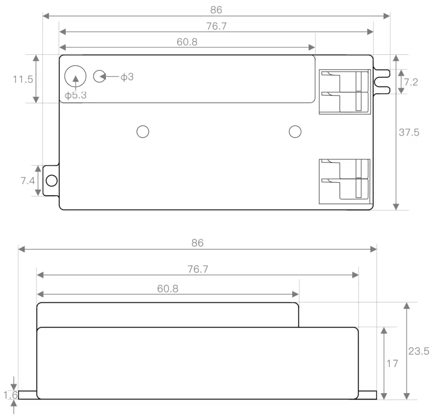
EDC212S-C Unit: (mm)
Function Description
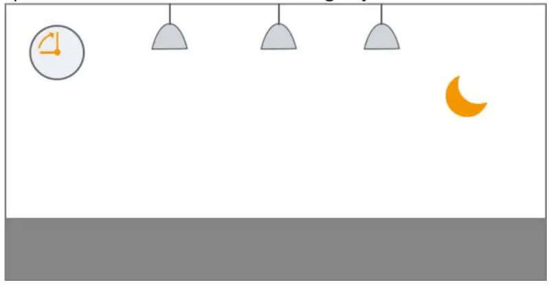
The photosensitive function is on
 |  |
| When the ambient light is bright enough, the light will not automatically light up even if a moving object is detected | When the ambient light is lower than the preset photosensitive threshold, the light will automatically light up when the sensor detects a moving object |
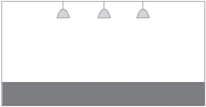
 |  |
| After the moving object leaves, the sensor will enter the delay time when it cannot detect the moving object and keep the light on | After the preset delay time, the light will automatically turn off |
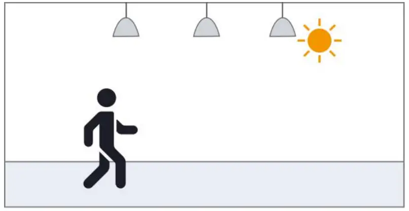
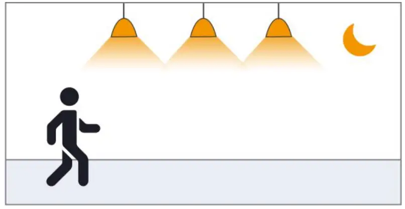
The photosensitive function is off
 | 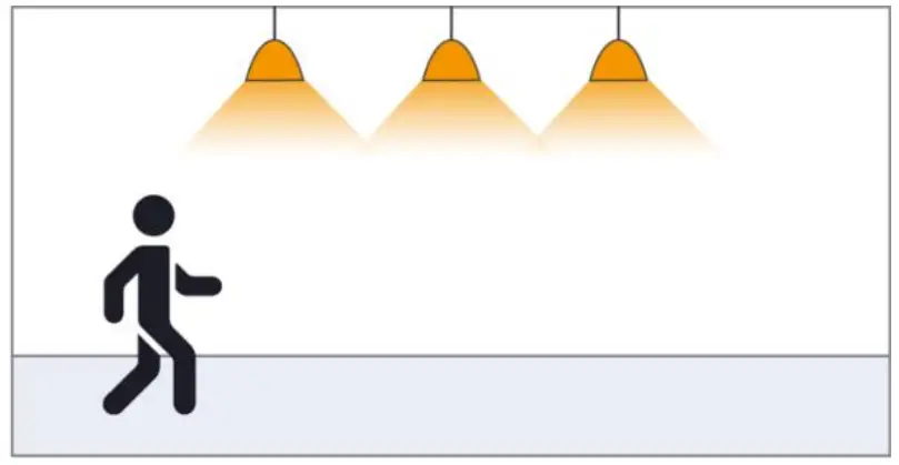 |
| No moving objects can be detected, and the lamp goes out | When the sensor detects a moving object, the light\ automatically lights up at 100% brightness and enters the set delay time |
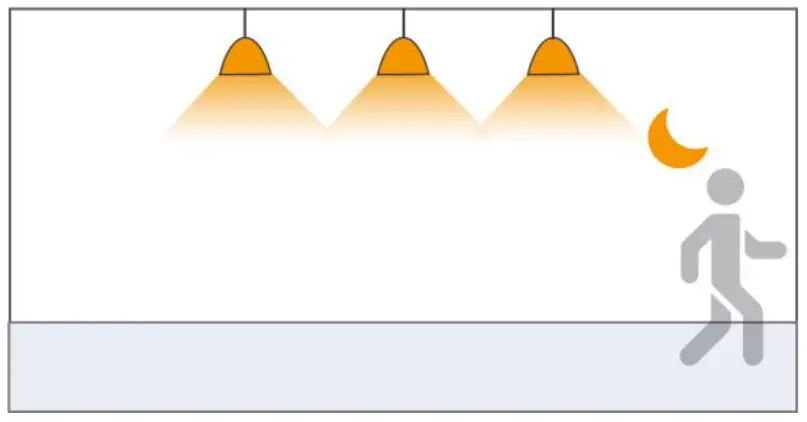
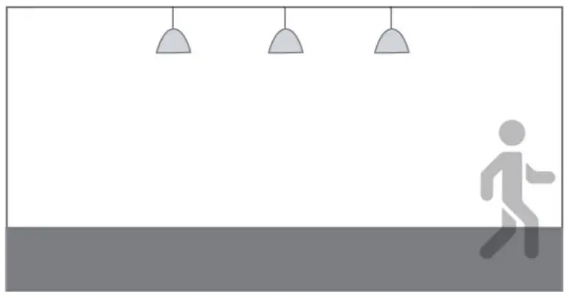 | |
| After the delay time, when the sensor cannot detect any moving objects, the lamp will be off |
Packaging Information
Support packaging: ![]() Blister packaging Bubble bag packaging PE bag packaging
Blister packaging Bubble bag packaging PE bag packaging
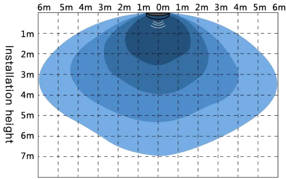
Detection diagram (distance can be adjusted according to actual application)
Detection sensitivity gear: ![]()
Ceiling installation diagram
Precautions
- When installing the product, the antenna board is required to maintain a certain height from the metal plane. It is recommended that the antenna board be kept at a distance of 5-12mm from the metal plane. It should not be close to or touch the metal plane, otherwise, the product may not work properly!
- The product has a better penetration effect on plastic and wood. At the same time, avoid metal shielding in front of the antenna, which will reflect microwaves and affect the actual sensing effect;
- Installing glass in front of the antenna will cause electromagnetic wave reflection and penetration attenuation, which will reduce the sensing distance of the sensor; installing ceramics in front of the antenna will also produce penetration attenuation, the greater the thickness, the more serious the attenuation;
- Please use a power supply with a small ripple for power supply, especially low-frequency ripples are likely to interfere with the operation of the sensor and cause false alarms. The recommended power supply capacitor is 470 uF; it is recommended that the power supply ripple be guaranteed within 100mV, and the ripple of 50mV is better;
- The signal output of the sensor, the load current capacity is weak, it may not be able to directly drive the back-end equipment.
- When multiple sensors are used in the same site, the spacing should be greater than 0.5m. It is recommended that the product installation spacing be greater than 1.5m. Too close installation distance may cause false alarms in individual cycles;
- Avoid high current circuit coverage on the antenna surface. The electromagnetic field generated by the circuit loop will interfere with the normal radiation of the antenna, causing false alarms or changing the sensing range;
- If the microwave sensor and wireless communication module (NB, Bluetooth, WIFI, 2.4G module) coexist in the application, the distance between the antenna of the Internet of Things module and the antenna of the microwave module should be increased in space. At the same time, try to shield or not receive the trigger signal of the microwave module when the Internet of Things module is communicating; microwave sensors or products with built-in microwave sensors will be interfered with by wireless routers. It is recommended to keep 1m away from high-power wireless communication equipment such as routers and wireless hotspots during installation. Above spacing
- The light sensor threshold is the test value in a sunny environment, with no shadows, and ambient light diffuse reflection conditions. The wavelength of light-sensing detection light covers 400nm~1100nm (including visible light, LED tube, infrared light band), the illuminance value detected by light-sensing may be different at different time periods and under different weather conditions;
- The antenna surface of the microwave sensor should be avoided facing the AC drive power supply, and at the same time as far away as possible from the rectifier bridge, transformer, switch tube, and other high-power devices of the drive power supply, so as to prevent the power frequency signal from interfering with the microwave module and causing false alarms;
- In the actual application environment of the electromagnetic wave emitted by the microwave sensor, the different reflectivity of the obstacle will bring about the different sensing range, which is a normal phenomenon;
- Product specifications and parameters may be upgraded without prior notice.
Product naming rules
| ED ED | Frequency band C | Product Category 2 | Product number 12 | Antenna type S | Characteristic- | Delay time 5Y | Customer Number – | Configuration 1 |
| □ S 3GHz □ F 6GHz ☑ C 5.8GHz □ Q 24GHz □ V 60GHz □ W 77GHz | □ 1 Microwave sensor ☑ 2 Microwave sensor switch □ 3 radar antenna □ 4 MCU □ 5 Microwave power supply □ 6 IC □ 7 other □ 8 networking | ☑ S Onboard antenna □ D Stacked antenna □ H high precision antenna □ C Ceramic antenna □ M Needle antenna | ☑ Y has photosensitive □ No photosensitive □ P programmable |
Configuration version description
【hardware】:
【software】:
History revision record
| version | time | description | Remarks |
| V1.0 | 2021-04-08 | first edition | – |
Federal Communications Commission (FCC) Compliance Statement for the USA
This device complies with part 15 of the FCC rules. Operation is subject to the following two conditions: (1)
This device may not cause harmful interference, and (2) this device must accept any interference received, including interference that may cause undesired operation.
could void the user’s authority to operate this equipment.
part 15 of the FCC Rules. These limits are designed to provide reasonable protection against harmful interference in a residential installation. This equipment generates, uses, and can radiate radio frequency energy and, if not installed and used in accordance with the instructions, may cause harmful interference to radio communications. However, there is no guarantee that interference will not occur in a particular installation. If this equipment does cause harmful interference to radio or television reception, which can be
determined by turning the equipment off and on, the user is encouraged to try to correct the interference by one or more of the following measures:
— Reorient or relocate the receiving antenna.
— Increase the separation between the equipment and receiver.
— Connect the equipment into an outlet on a circuit different from that to which the receiver is connected.
— Consult the dealer or an experienced radio/TV technician for help.
NOTE: THE GRANTEE IS NOT RESPONSIBLE FOR ANY CHANGES OR MODIFICATIONS NOT EXPRESSLY APPROVED BY THE PARTY RESPONSIBLE FOR COMPLIANCE. SUCH MODIFICATIONS COULD VOID THE USER’S AUTHORITY TO OPERATE THE EQUIPMENT.
RF exposure warning
This equipment complies with FCC radiation exposure limits set forth for an uncontrolled environment.
This product may not be collocated or operated in conjunction with any other antenna or transmitter.


