![]()
SS-955
Automatic Solder Feeder Soldering Station
User’s Manual
1st Edition, 2022
©2022 Copyright by Prokit’s Industries Co., Ltd.
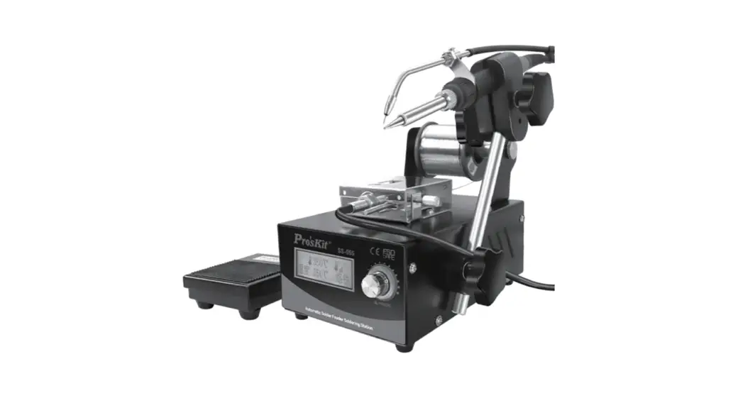
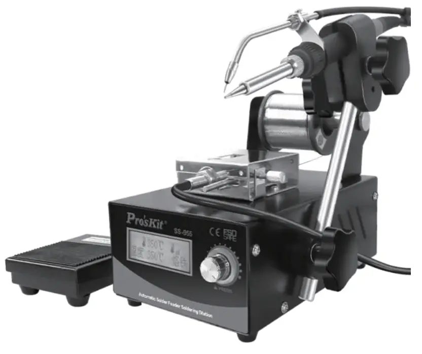
Product introduction
Thank you for purchasing the SS-955 Automatic Solder Feeder Soldering Station;
This product optimize the combination of automatic solder wire feed control device and soldering station; The solder wire output is accurate and can be flexibly adjusted, the feeding speed, time and return quantity can be controlled toachieve excel-lent effect, Suitable for all kinds of lead and lead-free operations, help you improve productivity.
Please read this manual carefully before use and operate in accordance with the instructions strictly. we will not bear any responsibility for product damage and other losses caused by incorrect use. Please keep it properly for future reference.
Safety precautions
![]() warning
warning
When the soldering iron is working, the tip of the soldering iron is at high temperature. If you want to replace the tip of the soldering iron or store the product, please turn off the power supply and unplug the wire plug, and then replace or store the soldering iron after it treturns to room temperature, so as to avoid personal injury and fire hazards.
![]() attention
attention
- Please use correct voltage source for this product.
- Do not operate in humid environment.
- Do not operate in flammable and explosive environment.
- Please keep the product clean and dry.
- Turn off the power supply when unused or leaving to prevent fire.
- Careful to prevent scalding when the soldering iron is working.
- Do not expose the product to the water or touch with wet hands, prevent electric leakage.
- Do not drop the product, or it may be damaged.
- Repaired and replaced must by professionals.
- Please use original parts when replacing.
Characteristic
- 2 in 1 design, soldering iron+ automatic solder wire feed, can be used separately.
- LCD display with backlight.
- Chinese simplified, traditional and English interface are optional.
- Encoder used conveniently, reliable and long service life.
- Temperature range: 200 ~ 480 ℃.
- The feeding mechanism adopts brushless stepping motor to control the solder wire output accurately.
- 60W copper transformer.
- Digital temperature calibration function, accurate and convenient.
- The soldering iron uses ceramic heating core (9SS-900N-HT), with long service life and fast heating up.
- The solder wire feed is controlled by handle or foot switch meet different require-ment.
- Adopt aviation plug connected reliably.
- Design for anti-static operation with anti-static socket, grounding port, metal case, etc.
3.1 Specification
| Model | SS-955B | |
| Automatic solder feeder | Voltage | 220V-240 V— 50Hz |
| Power | Soldering iron (60W) | |
| Soldering iron temperature | 200-480°C | |
| Shell | Steel sheet | |
| Display | LCD | |
| Setting | Encoder knob | |
| Calibration function | Y | |
| Password lock function | Y | |
| Restore settings | Y | |
| Sleep function | Y | |
| Transformer | 60W (copper wire) | |
| Fuse | 2A/250V (05*20mm) | |
| Anti static socket | 04.2mm (impedance 1Mc1) | |
| Power cord | VDE 1.5m(3*0.5mm2) | |
| Accessory | Foot switch • Soldering iron • Soldering • iron frame (with sponge) • Handle bracket solder wire support (Includ shaft) • elbow tube(‘ Ocm)/nozzle01.2mm &01.5mm each one • straight tube (17.5cm)/nozzle 01.8mm • screwdriver | |
| Dimension | 200*160*135mm (Including soldering Iron support) | |
| Weight | About 2.9kg | |
| Packing | Box | |
| Dimension /Weight | 270*230*175mm/ about 3.5kg | |
| Soldering Iron | Heating core | Ceramic heating core (955-900N-HT) |
| Working voltage | AC24V | |
| Transfor hose | 100cm (Anti scalding silicone pipe) | |
| Iron tip | 01.0mm (fi type ) (551-216N series available ) | |
| Sleeve of handle | Silica gel material | |
| Solder wire feed | Applicable solder wire | 00.5-1.5mm(0.5/0.6/0.8/1.0/1.2/1.5mm) |
| Control | Foot / hand | |
| Electric machinery | Stepper motor | |
| Solder wire feeding tube | 80cm(Intemal Teflon tube, outer anti scalding silicone hose) | |
| Working mode | Manual 0 / auto 1-9 | |
| Wire feeding length(LEN) | 0-99.5mm | |
| Wire feeding speed(SPD) | 1-40mm/s | |
| Interval tlme(INR) | 0-9.55 | |
| Return wire length(RET) | 0-19.5mm | |
※Any change without notice, please subject to the actual product.
※It is recommend not to set temperature than 450 ℃ for a long time use.
3.2 Soldering iron tips
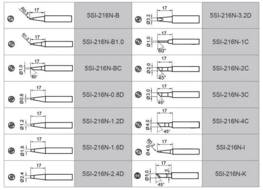
Soldering iron : 5SS-955-SI
Soldering iron heating core : 9SS-900N-HT
Foot switch : 5SS-955-TS
Packing list
Main device …………………… 1 set
Soldering iron…………………. 1 pc
Handle bracket……………….. 1 pc
Shaft……………………………. 1 pc
Foot switch …………………… 1 pc
Elbow tube ……………………… 3 pcs ti pc assembled on soldering iron)
Straight tube………………….. 1 pc
Power cord …………………… 1 pc
Screwdriver……………………. 1 pc
Instruction manual………….. 1 pc
Instructions
5.1 Function and display content
| Function setting 1. Language setting 2. Temperature unit setting 3. Password setting 4. Calibration function 5. Restore settings 6. Sleep time setting | Parameter settings 1. Working mode setting 2. Temperature setting 3. Wire feeding length setting 4. return wire length Setting 5. Wire feeding interval setting 6. Wire feeding speed settin |
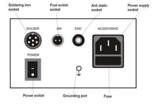
5.2 Schematic diagram of rear panel
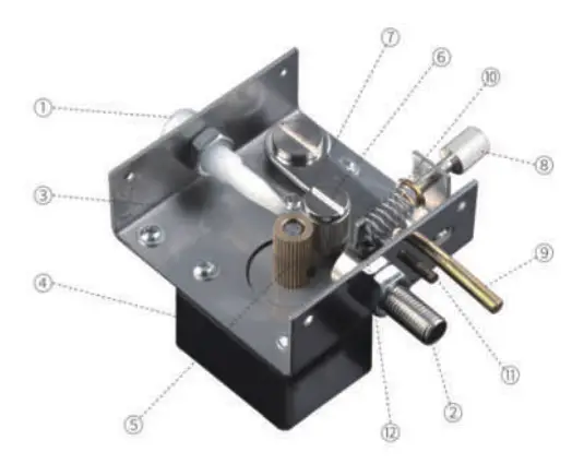
5.2.3 Structrue of feeding
| 1 | solder wire input port |
| 2 | outlet joint |
| 3 | Bottom case |
| 4 | Motor |
| 5 | drive gear |
| 6 | pressure gear |
| 7 | clutch iron plate |
| 8 | pressure adjusting nut |
| 9 | clutch lever |
| 10 | pressure regulating spring |
| 11 | gap adjusting screw |
| 12 | fixing screw |
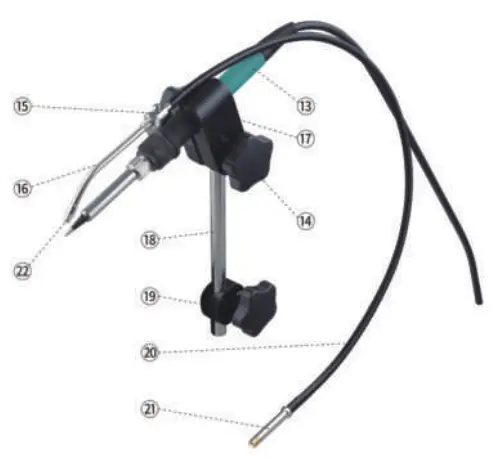
5.2.4 Structure of soldering iron part
| 13 | soldering iron |
| 14 | tight nut |
| 15 | handle tube separator |
| 16 | elbow tube |
| 17 | handle fixing clip |
| 18 | bracket |
| 19 | bracket fastener |
| 20 | transfer hose |
| 21 | hose connector |
| 22 | nozzle |
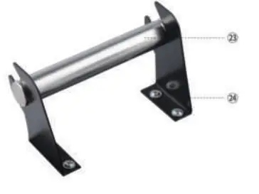
5.2.5 Solder wire support
| 23 | shaft |
| 24 | metal support |
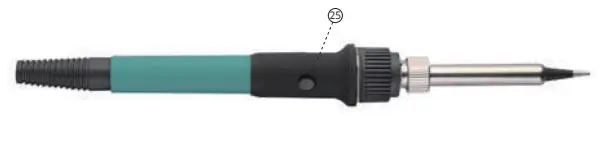
5.2.6 Soldering iron
25 button for solder wire feeding
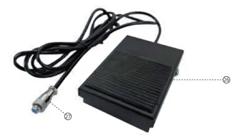
5.2.7 Foot switch
26 foot pedal
27 foot switch plug
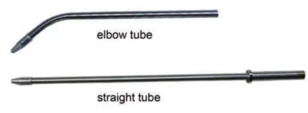
5.2.8 elbow and straight tube
5.3 Install and connection
5.3.1 Straight tube install: loosen the fixing screw 12 on the outlet joint 2, insert the straight tube to the outlet joint 2 and tighten the screw (D.
5.3.2 Elbow tube install: loosen the fixing screw 12 on the outlet joint Qz , insert the hose connector 2 into the outlet joint 2 and tighten the screw 12 . Loosen the locking screw on the handle tube separator 15 of the soldering iron, insert the other end of the hose into the elbow tube, cover the outer skin about 1 cm around the hose, and relock the screw.
Nozzle of the tube(Φ 1.8mm assembled), refer to the following:
| nozzle of elbow tube | corresponding solder wire |
| Φ1.2mm | 0.5-0.8mm |
| Φ1.5mm | 0.5-1.2mm |
| Φ1.8mm | 0.5-1.5mm |
| nozzle of straight tube | |
| Φ1.8mm | 0.5-1.5mm |
5.3.3 adjustment of the solder wire and the soldering tip position: rotate the handle tube separatorg 15 to change the combined position of the nozzle 22 and the tip, loosen the locking screw of the elbow tube, and pull the tube to change the length of its extension. 5.3.4 Foot switch install: insert the foot switch plug 27 into the SW jack on the back of the machine.
5.3.5 Solder wire install:
A Thread the shaft 23 into the solder wire , then put on the support 24.
B Pull out the solder wire and thread it through the solder wire input port Qat the back of the upper cover, push the clutch lever 1 to increase the gap between the two gears 5 and 6 to make the solder wire penetrate into the outlet joint, adjust the gap adjusting screw 9 and the pressure adjusting nut 11 , the solder wire between the drive gear and the pressure gear can be well fixed by the gear without slipping, and the solder wire is not deformed due to too much extrusion. C Loosen the fixing screw ©of the outlet joint > pull off the hose connector C), Insert the solder wire pass through the outlet joint 8 into the hose connector , fasten-ing the fixing screw
C) D Connect the power plug on the back of the machine to the power correctly, turn on the power switch, straighten the transfer hose 21 as possible, and press the switch of the foot switch 25 or handle button 26 until the solder wire is sent to the nozzle. 5.3.6 bracket installation: loosen the bracket fastener (Don the machine, install the bracket into the bracket seat hole, tighten the tight nut to fix it. 5.3.7 Solder iron installation: loosen the tight nut 14, remove the handle fixing clip, ,17 place the handle into the fixing clip, reinstall and tighten the tight nut is , insert the soldering iron aviation plug into the SOLDER socket on the back of the machine, and lock the screws. 5.3.8 Soldering iron position adjustment: the bracket fastener 0 can adjust the height of the handle, and the angle up or down (not too large to prevent the passage of the solder wire, keep the solder wire in the appropriate position).
Note:
When unscrewing the handle tube separator, be more careful not to damage the heating core; If the foot switch 26 is pressed and the solder wire cannot be sent out automatically, adjust the pressure adjusting nut 8 ; The outlet joint shall not be excessively bent or forcibly twisted to prevent the solder wire from blocking; If the soldering iron is installed, it will be heated when the power switch is turned on (the display screen will be on). Please pay attention to avoid scalding during installation.
5.3.9 operation mode: two operation modes can be selected as required, elbow mode and straight mode.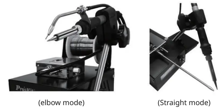
- Use of ESD socket for anti-static
This port provides the connection of anti-static working pad, wrist strap and other similar devices. - Use of Grounding port
1. This port provides a connection to a ground point.
2. Pay attention to the connection of power supply and grounding to ensure it is reliable.
5.4 Operating instructions
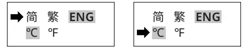
5.4.1 Language and temperature unit setting:
Turn on the power, long press the panel knob to enter the function setting menu first, rotate the encoder’s knob (here in after the knob). When the LCD interface appears on the display screen, select the “ENG” language and press the knob again to confirm.
Rotate the knob, and when the arrow indicator goes to the next column, it indicates to “℃ / ℉”, select the required temperature unit, and press the knob again to confirm.
5.4.2 Working parameter setting:
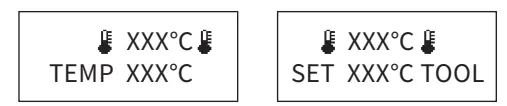
Rotate the knob, and “TOOL ” flashes on the right side of the second column (the “TEMP” is displayed on the left), or “FEED” (related to wire feeding), indicating that the working parameter setting state is entered. At this time, continue to rotate the knob to set the data, and press the knob to enter the corresponding parameter. On any parameter page, press the knob to directly enter the temperature setting before entering the setting state。
- Temperature setting: when “TEMP” is displayed in the second column on the left of the display screen, press the knob to enter the temperature setting state, rotate the knob to set the required temperature, adjustment range is 200 ~ 480 ℃, and press the knob to save the setting.

- Feeding length: rotate the knob, when “LEN” is displayed in the second column _ on the left, press the knob to set the feeding length, the adjustment range is _ 0 ~ 99.5mm, and press the knob to save the setting;
- Return length: rotate the knob, when “RET” is displayed in the second column _ on the left, press the knob to set the return length, the adjustment range is _ 0 ~ 19.5mm, and press the knob to save the setting;
- Interval time: rotate the knob, and when the “INR” is displayed in the second _ column on the left, press the knob to set the interval time, the adjustment range _ is 0 ~ 9.5s, and press the knob to save the setting;
- Feeding speed: rotate the knob, when the “SPD” is displayed in the second _ on the left, press the knob to set the output speed, with the adjustment range _ of 1 ~ 40mm / s, and press the knob to save the setting;
- Working mode: rotate the knob. When the “MODE” is displayed in the second _ column on the left, press the knob to enter the working mode. The adjustment _ range is 0 ~ 9. Press the knob to save the setting;
• “0” is the manual working mode. The feeding time is manually controlled by the foot switch or by the handle button.
• “1-9” is the automatic working mode. Just press the foot switch or handle button to automatically complete the feeding according to the set length. When the number is “1”, it completes one automatic control cycle, and when the number is set to “2”, it completes two control cycles. The pause between cycles is determined by setting the “interval time” parameter.
• set “1” and the feeding length is set “0”, once working it will continues till the foot switch or handle button press again to stop.
• The temperature set less than 200℃, the soldering iron will be closed , solder wire feeding function can be use seperatly.
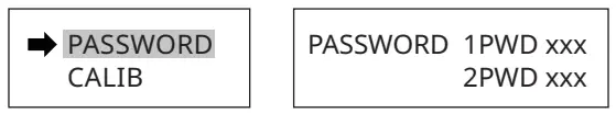
5.4.3 Password setting:
Long press the knob and turn it to “PASSWORD”. Press the knob to enter the password setting. only when “1 PWD” and “2 PWD” are the same number you can save the setting parameters and exit after “LOCKED!” displayed. If the number input are different, “FAIL!” will displayed.
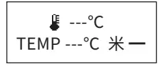
The LCD display show a symbol of “ ![]() ”under the Password Setting Mode, you can’t set parameters and there will be “ENTER THE PWD!” required, enter the Password setting and input the password to unlock, the symbol of “
”under the Password Setting Mode, you can’t set parameters and there will be “ENTER THE PWD!” required, enter the Password setting and input the password to unlock, the symbol of “![]() ” disappeared and then you can set parameters。 When “1PWD” input “0” and “2PWD” input “0”, press the knob can clear the password set before. once you forget password, you can input number “166” to unlock.
” disappeared and then you can set parameters。 When “1PWD” input “0” and “2PWD” input “0”, press the knob can clear the password set before. once you forget password, you can input number “166” to unlock.
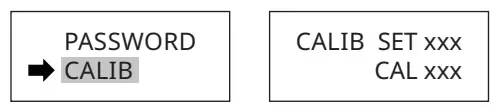
5.4.4 Temperature calibration:
First to measure the temperature of the soldering iron and record the reading used by temperature tester. then long press the knob to enter the parameter setting, select the “CALIB”, at SET position input the data which setting temperature, and CAL position
input the data which test value(reading), and click the knob to save the setting and exit. (temperature calibration set 2 points,one higher than 350℃,another one lower than 350℃ which can obtain the linearity of a wide temperature range).
5.4.5 Restore settings:
Long press the knob and rotated to “RESTORE DEFAULT”, press the knob again and the parameters setting will automatically return to the initial state.
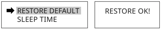
5.4.6 Sleep time setting:
Long press the knob and rotate to “SLEEP TIME”. Press the knob to enter the sleep setting, set turn off the sleep mode or sleep time from 1-240min according to needs ; no operation (foot pedal, handle button) for a long time arrived sleep time setting, the “SLEEPING” will be displayed on the LCD, the tip temperature is down to 200℃. turn the knob, touch foot switch or handle button can wake up directly, and the soldering iron will return to the working set quickly.
![]() Note:
Note:
It will not remember and exit automatically while no operations for 5 seconds of the knob.
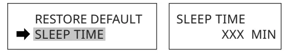
5.5 Fuse replacement
When fuse is blown, replace it with the same type of fuse(refer to the picture below).
1) Unplug the power cord from the power receptacle.
2) The fuse holder is located under the AC power receptacle. Use a slotted (–) _ screwdriver to open the fuse holder.
3) Replace the fuse with a new one (Φ 5*20mm 2A).
4) Put the fuse holder back in place.
5.6 Troubleshooting
| Faults | Causes | Solution |
| Not work | Fuse blown | Replace the fuse (2A/250V) |
| Power not connected reliably | Check the power connection and plug it in | |
| Shows”H-E” “S-E”on display | Loose connection | Reconnect the soldering iron plug or replace the heating core |
| The heating core is burned or the assembly wire is damaged | Reference the heating core connection circuit | |
| LCD display confusion | Chip failure | Return to dealer |
| Unable to set temperature | Password set | Enter password or clear it |
| Temperature deviation of soldering iron tip | Poor temperature calibration | Recalibration |
| The soldering iron tip can not adhere with tin | Soldering iron tip oxidized | Clean or replace tips |
| The temperature of soldering iron was set too high | Set temperature no more than 450°C for long use. | |
| Feeding failure | Chip or motor failure | Return to dealer |
| Transfer hose is blocked or deformed | Rearrange the hose and dredge it | |
| Button switch failure | Replace switch component or soldering iron | |
| Foot switch failure | Replace the Foot switch |
![]() warning
warning
Turn off the power and remove the power cord before maintenance, otherwise electric shock may occur.
Please contact the dealer beyond the above faults.
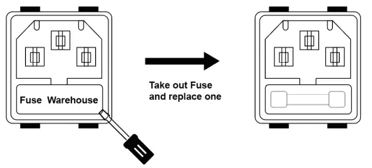
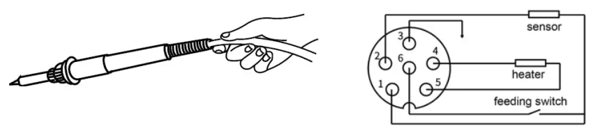
How to inspection the soldering iron
Check the resistance between the pins of the connecting plug as follows:
| 4~5 ( Heater ) | ≈4Ω |
| 1~2 ( Temperature sensor ) | ≈50Ω |
| 1~6 ( feeding switch ) | ON |
| 3~soldering iron tip( Earthing) | <2Ω |
- The resistance value between the plug pins is different from the resistance value in the table, disassembly the soldering iron to confirm whether the resistance value of the PCB is correct.
- The measured resistance value on PCB is correct, indicate that the soldering iron wire is damaged, refer diagram to check the wire connect situation as below.

- The resistance between the 3 pin of the plug and the soldering iron tip is greater than the table value, wipe the point of junction where oxidized with sandpaper.

https://www.prokits.com.tw/
PROKIT’S INDUSTRIES CO., LTD
http://www.prokits.com.tw
Email: [email protected]
©2022 Prokit’s Industries Co.. LTD. AI rights reserved 2022001(C)


