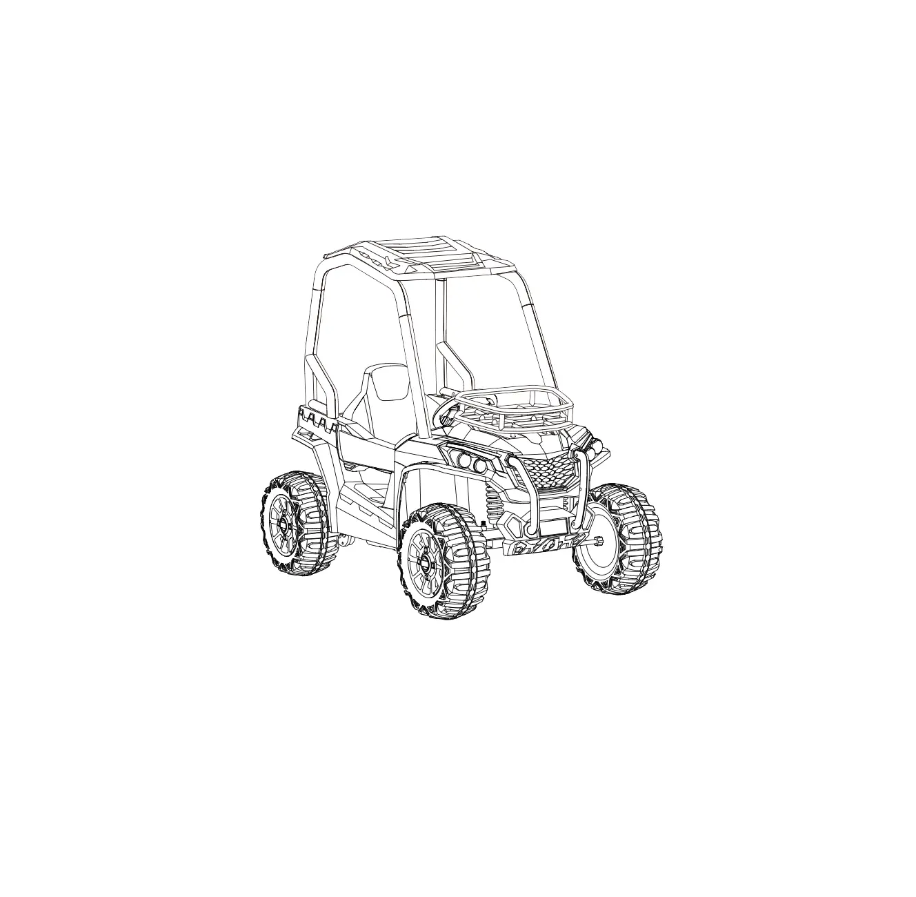
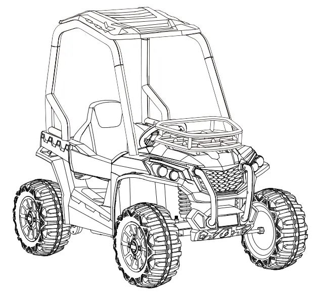
Supercheap Auto 616617 UTV Kids Ride On Explorer
 WARNING
Must be assembled by an adult.
- Suitable for for 37-96 months
- Maximum user weight: 30 kg
About Your New Ride-On
On the purchase of your new Ride-On.
This ride-on will provide your child with many miles of riding of enjoyment. To help assure you and your rider a safe ride we ask you to please read this manual carefully, and keep it for future reference. Follow the recommendations in this manual, they are designed to improve the safety and operation of your ride-on car and it’s rider.
SPECIFICATIONS:
| Battery | 12V10AH*1 |
| charger | Input: 100-240VAC 50-60Hz 0.56A |
| Output: 15.0VDC 1.0A |
Suitable age: 37-96 months
Load Capacity: 30kg
Speed: 3-6 km/h
Size of car: 118 * 76 * 104 cm
Power way: Charging type
Charge time: 8-12 hours
User Notice
![]() WARNING!
WARNING!
- CHOKING HAZARD – Small parts. Not suitable for children under 36 months. The product contains small parts, keep children away when assembling.
- ADULT ASSEMBLY REQUIRED.
- Always remove protective material and poly bags and dispose before assembly.
- Protective equipment should be worn. Always wear shoes and sit in the seat when operating the vehicle.
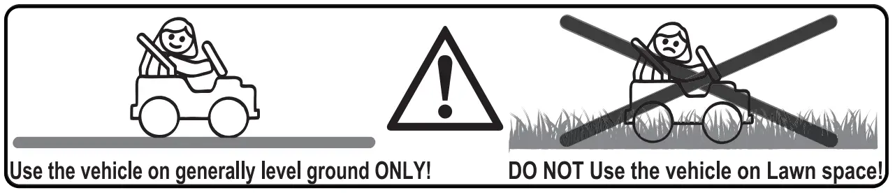
- Only drive on level ground. Never use on the lawn.
- Never leave a child unattended.
- Keep your hands, hair, and clothes away from moving parts .
![]() SAFETY
SAFETY
- The following safety hazards may result in serious injury or death:
- Never leave child unattended. Direct adult supervision is required. Always keep child in view when child is in vehicle.
- To reduce the risk of injury, adult supervision is required. Never use in roadways, near motor vehicles, on or near steep inclines or steps, swimming pools or other bodies of water, always wear shoes, and never allow more than 1 rider.
- Never use in unsafe conditions such as snow, rain, loose dirt, mud, sand, or gravel, otherwise may result in an unexpected accident such as tipping over, and could damage the electrical system or battery
- Not to be used in traffic.
- This toy should be used with caution since skill is required to avoid falls or collisions causing injury to the user or third parties.
- This toy is unsuitable for children under 36 months due to its maximum speed; Maximum user weight is 30kg.
- This toy has no brake.
![]() BATTERY INFORMATION
BATTERY INFORMATION
- Non-rechargeable batteries are not to be recharged.
- Rechargeable battery doesn’t need to be removed from the vehicle before charging.
- Rechargeable batteries are only to be charged under adult supervision.
- Different types of batteries or new and used batteries are not to be mixed.
- Batteries are to be inserted with the correct polarity.
- Exhausted batteries are to be removed from the toy.
- The supply terminals are not to be short-circuited.
Parts Diagram
HINT: Some parts shown are assembled on both sides of vehicle
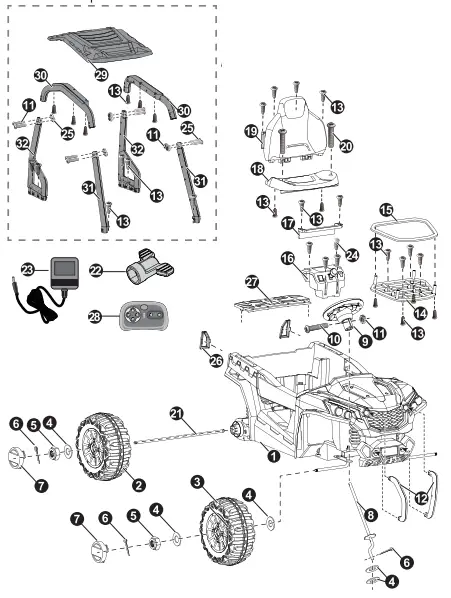
| PART NAME | Q’ty (pcs) | REMARKS | |||
| Vehicle body | 1 | ||||
| Rear wheel | 2 | ||||
| Front wheel | 2 | ||||
| 012 washer | 8 | ||||
| Lock nut | 4 | ||||
| Split pin | 5 | ||||
| Hubcap | 4 | ||||
| Steering column | |||||
| Steering wheel | |||||
| M5x35 machine screw | |||||
| 05 nut | 9 | ||||
| Front bumper | 2 | Left and right | |||
| 04×12 flat head screw | 28 | ||||
| Bakset base | |||||
| Bakset fence | |||||
| Shift lever assembly | |||||
| Protecting board | |||||
| Seat | |||||
| Seat back | |||||
| M5x16 machine screw | 2 | ||||
| Rear axle | |||||
| Spanner | 2 | ||||
| Charger | 1 | ||||
| 04×12 round head screw | 4 | ||||
| M5x25 machine screw | 8 | ||||
| Taillight cover | 2 | Left and right | |||
| Rear bed board | |||||
| Remote controller | |||||
| Roof | |||||
| Roof beam | 2 | Left and right | |||
| Roof front support | 2 | Left and right | |||
| Roof rear support | 2 | Left and right | |||
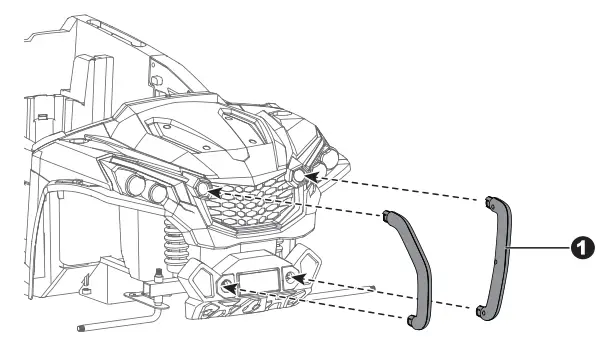
Attach the Front Bumpers & Tailight Cover
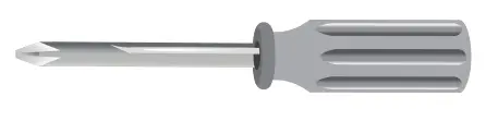
Assembly tools required (not included):
- Screwdriver
- Long nose pliers
- Insert the tabs on the front bumper into the holes on the front of the vehicle, push until you hear it “click” into place.
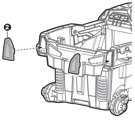
- Insert the left and right taillight covers and “snap” into place.
Attach the Steering Column
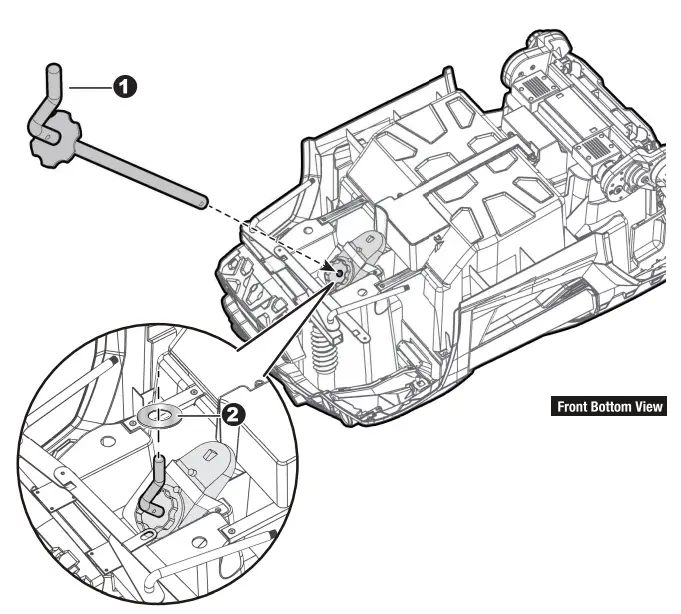
Turn the vehicle body downside up.
- Insert the straight end of the steering column through the hole on the steering gear box, the hole on the vehicle body, and out through hole on the dash. Ensure the gear part on the steering column matchs up with the steering gear box.
- Slide a Ø12 washer onto the steering column from the bent end.
Reset the Front axle
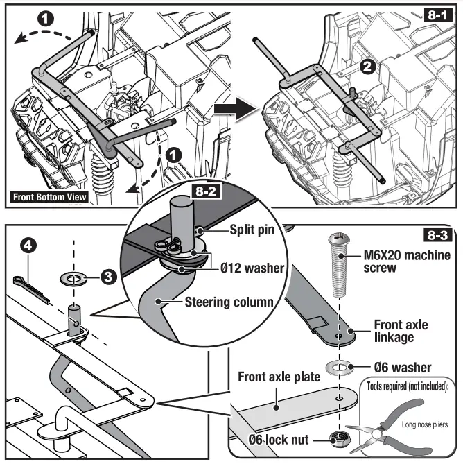
Cut off the plastic tie on the front axle with scissors.
1,2. Adjust the front axle plate so that the axle is in the correct position as shown (8-1);
3. Slide a Ø12 washer onto the steering column from the bent end.
4. Insert the split pin into the hole on the bent end of the steering column. Bend the ends of split pin back using a long nose pliers (not included).
5. Remove the M6x2Ø machine screw, Ø6 washer and Ø6 lock nut from the front axle linkage. Reinsert the M6x2Ø machine screw through the hole on the front axle linkage, the Ø6 washer and the hole on the front axle plate, then fasten the Ø6 lock nut to the opposite end of the screw with a Long Nose Pliers(Not included).
Attach the Rear Wheels
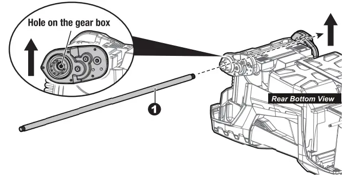
Cut off the plastic ties on the gear boxes. Remove all the parts from the rear axle.
- Insert the rear axle through the hole in the vehicl body, when inserting it half way, lift the another gear box so that the rear axle can go through it and protrude out. Make sure that the rear axle is centered with left and right ends exposed the same distance outside of the ride-on toy body.
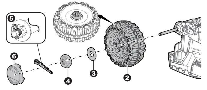
- Slide the rear wheel onto the rear axle .
- Slide the Ø12 washer onto the rear axle.
- Tighten a lock nut to the end of the rear axle with a spanner.
Repeat the 2-4 steps for the other rear wheel.
HINT: An extra spanner has been provided to hold the Lock Nut on the other side of the rear axle while tightening the Lock Nut on the other side. DO NOT over tighten. - Insert a split pin into the hole on the each end of the rear axle. Bend the ends of split pins back using a long nose pliers (not included).
- “Snap” a hubcap to each rear wheel.
Attach the Front Wheels
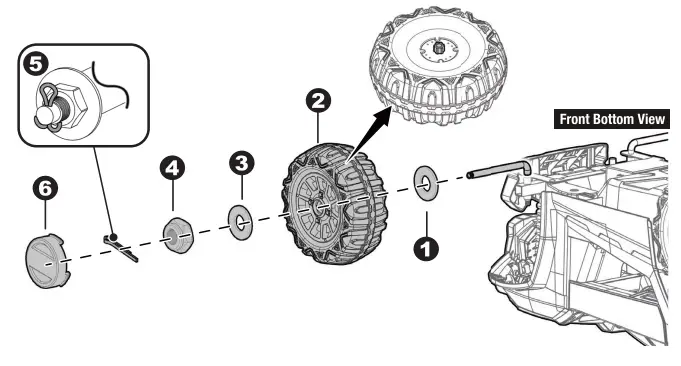
Remove all the parts from the front axle.
- Slide a Ø12 washer onto the front axle.
- Slide a front wheel onto the front alxe.
- Slide a Ø12 washer onto the front axle.
- Tighten a lock nut to the end of the front axle with a spanner. DO NOT over tgithen.
- Insert the split pin into the hole on the end of the rear axle. Bend the ends of split pin back using a long nose pliers (not included).
- “Snap” the hubcap to the wheel. Repeat the above procedure to assemble the other front wheel.
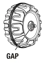 | After assembling any wheel to the axles, please check the gap between the screw thread and the collapsible (refer to below picture), if the gap is too big, please add two or three washers inside the wheel, but after tightening the nut outside the wheel, please turn the wheel by your finger to check if the wheel can run smoothly, this is very important, because if the wheel can run smoothly, it is ok, but if the nut press the wheel and the wheel can’t run smoothly, the motor will be broken easily! Then you need to decrease one or two washers to make sure the wheel can run smoothly! |
Attach the Steering Wheel
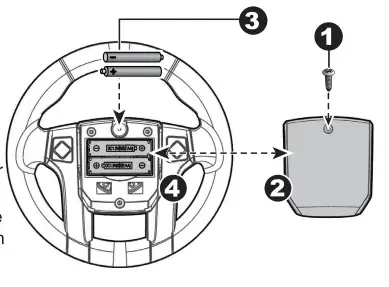
Pease follow the steps 1-4 to add the batteries (Not Included), and refer to the battery infonnation on page 2.
- With a screwdriver remove the screw on the battery cover located in the center of the steering wheel.
- Remove the battery cover from the top of the battery compartment.
- Insert 2×1 .5 AA batteries in their correct polarities.
- Place the battery cover over the battery compartment and fasten with the screw you removed in step one.
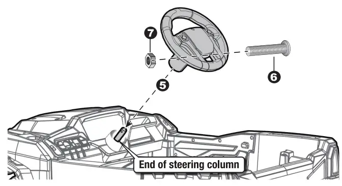
Attach the Steering Wheel
Remove the M5x35 machine screw and 05 nut from the steering wheel.
Turn the vehicle body upright. - Place the steering wheel over the the steering column, protruding from the middle of the steering wheel base.
- Align the holes on each side of steering wheel with the holes at the end of the steering column.
- Fasten a nut on the opposite end of the screw to secure the steering wheel to the steering column.
Attach the Shift Level Assembly & Protecting Board
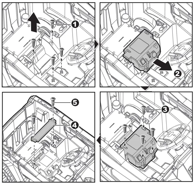
- Lift up the shift lever assembly and remove the four 04×12 round head screws with a screwdriver.
- Push the Shift Lever Assembly forward and locate it over the 4 screws mounting brackets as shown.
- Secure it by tightening the four removed screws.
- Fit the protecting board to the vehicle body.
- Tighten securely with two 04×12 flat head screws with a screwdriver.
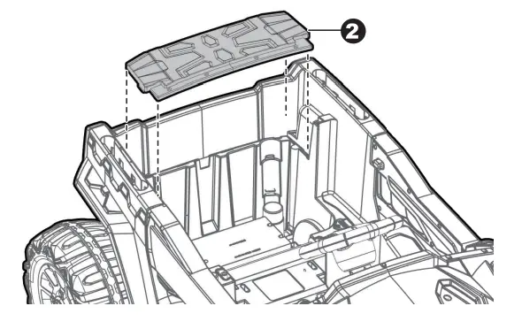
Connect the Power Supply & Attach the Rear Bed Board
- Plug the battery connector into the vechiel connector, push firmly.
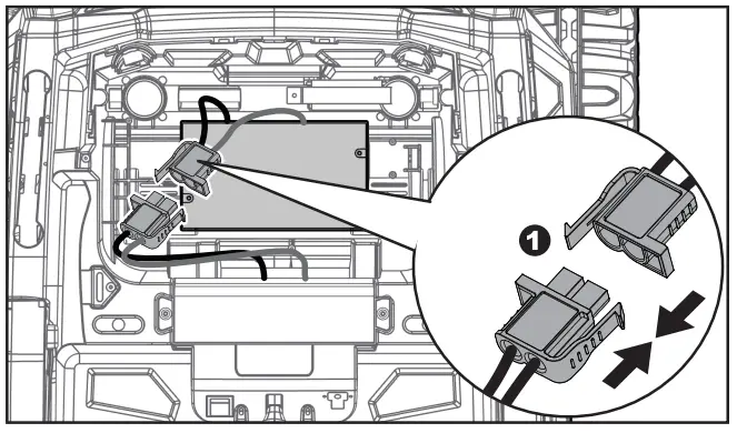
- Fit the tabs on the rear bed board into the slots located in the rear vehicle body, and press down until it “clicks” into place.
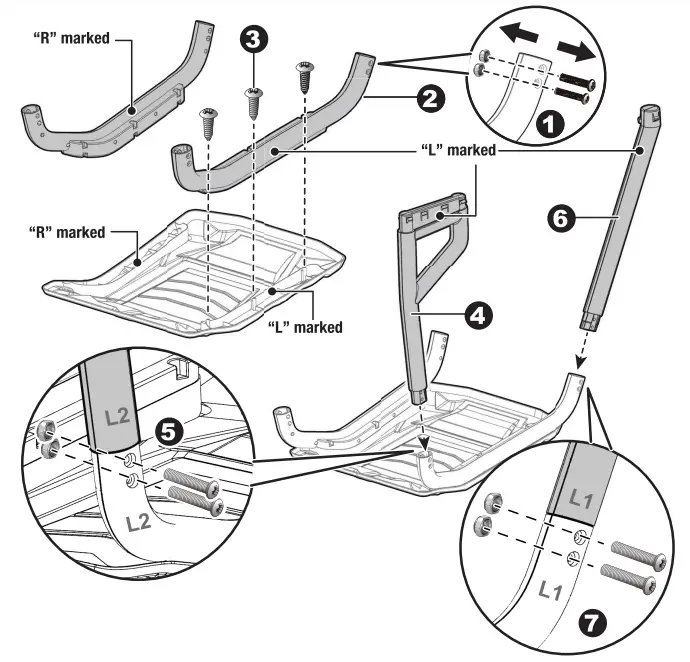
Attach the Seat & Attach the Basket
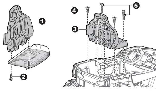
- Fit the seat back to the seat.
- Insert two 04×12 flat head screws from the the bottom side of the seat, through the seat and into the seat back, and tighten.
- Fit the seat assembly to the vehicle body.
- Insert four Ø4×12 flat head screws on the seat back and tighten.
- Insert two M5x16 machine screws through the seat and into the vehicle body, and tighten with a screwdriver.
6-7. Fit the basket fence to the basket base, insert four Ø4×12 flat head screws and tighten.
8-9. Fit the cargo basket to the bonnet. Insert four Ø4×12 flat head screws and tighten.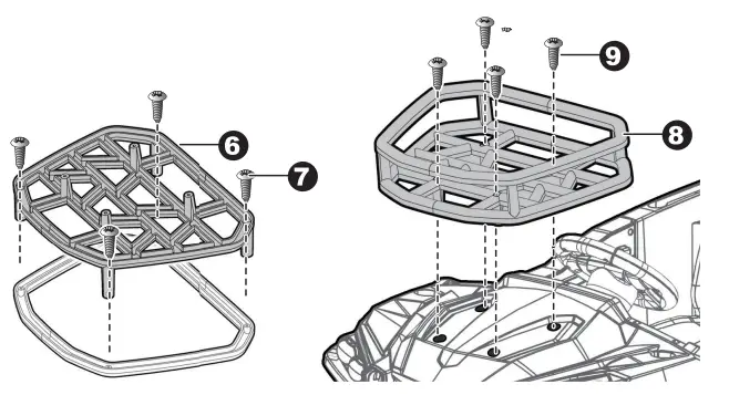
Attach the Roof(1)
HINT: The roof, roof beams, roof front supports and roof rear supports are marked “L” and “R”, aslo they are designed to assemble together in only one way. Please follow the guides: L to L (L 1 to L 1, L2 to L2), R to R (R1 to R1, R2 to R2)
- Using a screwdriver to remove the M5x25 machine screws and Ø5 nuts from the left and right roof beams.
- Fit the both roof beams to the roof.
- Insert three Ø4×12 flat head screws and tighten on each beam.
4-5. Fit the rear rollbar support to the roof beam, secure with M5x25 machines *2 and Ø5 nut *2 you removed in step one. Repeat for the other side. (L2 to L2, R2 to R2)
6-7. Fit the front rollbar support to the beam, secure with M5x25 machines *2 and Ø5 nut *2 you removed in step one. Repeat for the other side. (L 1 to L 1, R1 to R1)
Attach the Roof(2)
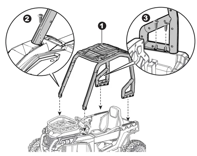
- Fit the roof assembly to the vehicle body.
- Insert a Ø4×12 flat head screw through the roof front support and into the bonnet, and tighten with a screwdriver. repeat for the other side.
- Insert two Ø4×12 flat head screws through the rear rollbar support and into the vehicle body. and tighten with a screwdriver. repeat for the other side.
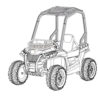
Assembly completed.
Use Your Ride-on
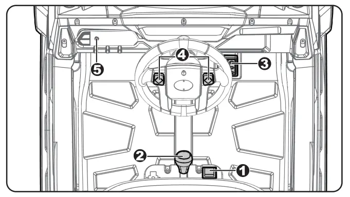
- Power button: Turns the vehicle on and off.
- Low speed forward/reverse shifter: Changes the direction that vehicle moves from forward to reverse.
• To move the vehicle forward, shift the lever to top position.
• To move the vehicle backward, shift the lever to down position. - Foot pedal: Applies power (speed) to the vehicle.
• To move the car, press the pedal down.
• To brake or slow down, release pressure from the pedal. - Sound buttons: Press for sound playing.
- 3.5mm AUX input: Allow the audio from your portable music player or phone to be played through the vehicle speakers. MP3 format ONLY.
![]() IMPORTANT
IMPORTANT
- Always stop vehicle when changing the speed (if equipped) or direction to avoid damage the gears and motor.
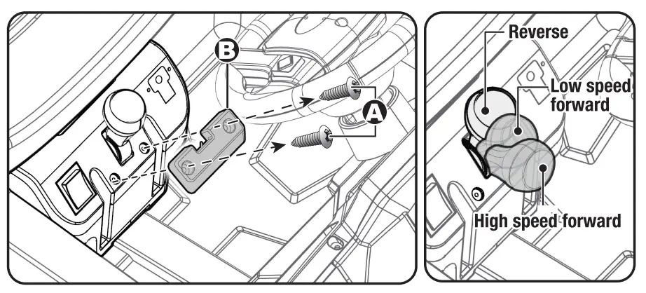
Using the High Speed
![]() IMPORTANT
IMPORTANT
- The High Speed Protective cover must be removed by an adult.
- Before remove the HIGH SPEED protective cover: Make sure your child knows how to steer, how to start and stop the product and knows the rules for safe driving.
A. Remove the two screws on the top of the high speed protective cover with a screwdriver.
B. Remove the high speed protective cover.
Then you can push the shifter into the “high speed” position.
C. Press down the foot pedal.
HINT: The product is designed to operate in low speed only in reverse.
Using the Media Player
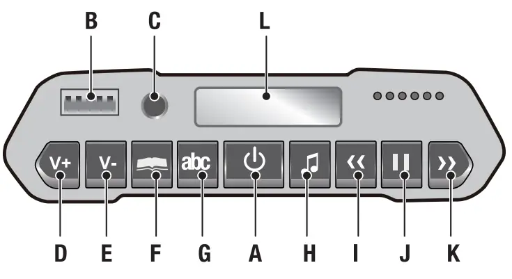
A. Player Power.
B. USB interface: Allow the audio from your portable device to be played through the vehicle speakers. MP3 format ONLY.
C. 3.5mm AUX input: Allow the audio from your portable music player or phone to be played through the vehicle speakers. MP3 format ONLY.
When use MP3 port to connect to phone, the volume only can be adjusted by phone, the control panel on car could not adjust the volume.
D. Increase volume
E. Decrease volume
F. Storytelling mode
G. English learning mode
H. Music mode
I. Previous
J. Play/pause
K. Next
L. Digital voltmeter: Check the power remaining of your battery. Please charge the battery when the display value is less than 12.5 V
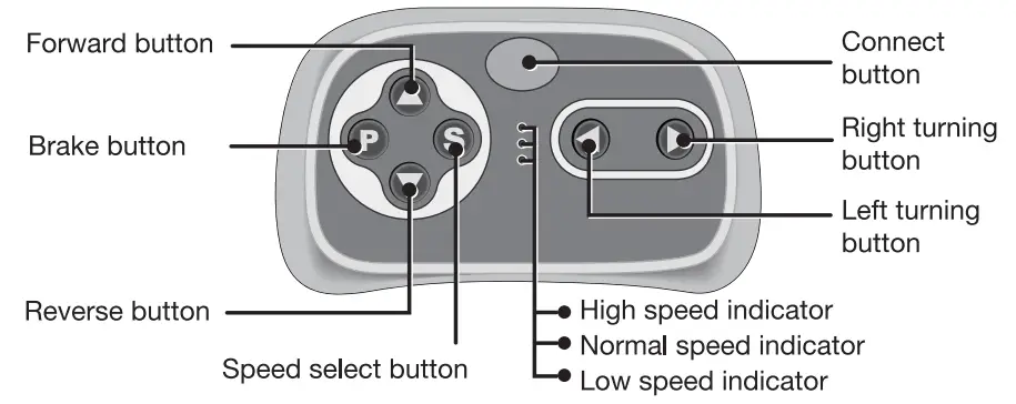
Use the 2.4G Remote Controller
![]() WARNING: ADULT OPERATING REQUIRED!
WARNING: ADULT OPERATING REQUIRED!
The remote control has precedence over foot pedal operation.
(The foot pedal won’t work while you operate the Remote Controller)
- Connect button (build connection)
Lift the battery compartment door on the back of the controller and insert two AAA (LR03) batteries. NOTE: Batteries not included. Refer to the battery information on page 2.
Press and hold the connect button for 3 seconds, the low-speed indicator flashes, mean that the remote controller is in the connected state. Then power on the vehicle:
The low-speed indicator goes to long bright, means the connection successful.
If the low-speed indicator no response, means the connection failed. Turn off the remote conntroller (by removing the batteries) and the vehicle. And try again. - Brake button
Press the button to stop the vehicle, press it again to release the brake. - Speed select button
The switch operates the vehicle to move in low, normal or high speed.
HINT: The vehicle is designed to operate in low speed only in reverse.
NOTE:
- Leave the remote controller idling for about 10 seconds, it will shut down automatically.
- After you replacing the batteries of the remote controller, please rebuild the connection. (step 1)
Charging
![]() WARNING!
WARNING!
- ONLY an adult is allowed charge and recharge the battery!
- This product with Charging Protection: when charging, all functions will be cut off.
- The POWER SWITCH (BUTTON) must be turned in OFF position when charging.
- Before the first use, you should charge the battery for 4-6 hours. Do not recharge the battery for more than 10 hours to avoid overheating the charger.
- When the vehicle begins to run slowly, recharge the battery.
- After each use or once a month minimum recharge time as 8 to 12 hours, less than 20 hours at most.
- Use the only rechargeable battery and charger supplied with your vehicle. NEVER substitute the battery or the charger with another brand. Using another battery or charger may cause a fire or explosion.
- Do not use the battery or charger for any other product.
- If your ride-on with a Digital voltmeter(IF EQUIPPED), the magnitude of voltage will tell you how much power is remaining in the battery when you must recharge the battery. Make sure the vehicle is stop!
| 12V product | less than 12.5V | The battery needs to be charge. |
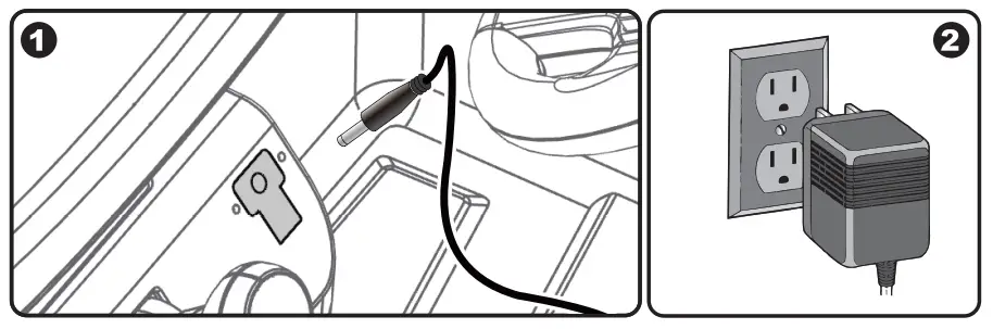
- Plug the charger port into the input socket (the socket below the seat).
- Plug the charger plug into a wall outlet. The battery will begin charging.
Battery Disposal 
The battery will eventually lose the ability to hold a charge. Depending on the amount of use, and varying conditions, the battery should operate for one to three years.
Important! Recycle the dead battery responsibly. The battery contains lead acid (electrolyte) and must be disposed of properly and legally. It is illegal in most areas to incinerate lead acid batteries or dispose of them in landfills. Take it to a federal or state-approved lead acid battery recycler, such as local automotive battery retailer.
Do not throw the battery away with your regular household waste!
| Problem | Possible Cause | Solution |
| Vehicle does not run | Battery low on power | Recharge battery. |
| Thermal fuse has tripped | Reset fuse, see <Fuse> | |
| Battery connector or wires are loose | Check that the battery connectors are firmly plugged into each other. If wires are loose around the motor contact your distributor please. | |
| Battery is dead | Replace battery, contact your distributor please. | |
| Electrical system is damaged | Contact your distributor please. | |
| Motor is damaged | Contact your distributor please. | |
| Vehicle does not run very long | Battery is under charged | Check that the battery connectors are firmly plugged into each other when recharging |
| Battery is old | Replace battery, contact your distributor please. | |
| Vehicle runs sluggishly | Battery low on power | Recharge battery, contact your distributor please. |
| Battery is old | Replace battery, contact your distributor please. | |
| Vehicle is overload | Reduce weight on vehicle. | |
| Vehicle is being used in harsh conditions | Avoid using vehicle in harsh conditions, see <Safety>. | |
| Vehicle needs a push to go forward | Poor contact of wires or connectors | Check that the battery connectors are firmly plugged into each other. If wires are loose around the motor, contact your distributor please. |
| “Dead Spot” on motor | A dead spot means the electric power is not being delivered to the terminal connection and the vehicle needs repair. Contact your distributor please. | |
| Difficult shifting from forward to reverse or vice-versa | Attempting to shift while the vehicle is motion | Completely stop the vehicle and shift, see <Use Your Ride-On> |
| Loud grinding or clicking noises coming from motor or gear box | Motor or gears are damaged | Contact your distributor please. |
| Battery will not recharge | Battery connector or adapter connector is loose | Check that the battery connectors are firmly plugged into each other. |
| Charger not plugged in | Check that the battery charger is plugged into a working wall outlet. | |
| Charger is not working | Contact your distributor please. | |
| Charger feels warm when recharging | This is normal and not a cause for concern |
Completely read through this manual and the troubleshooting guide table before calling. If you still need help resolving the problem Contact your distributor please.
Maintaining
- It is parents’ responsibility to check main parts of the toy before using, Must regularly examine for potential hazard, such as the battery, charge, cable or cord, plug, screws are fastening enclosure of other parts and that in the event of such damage, the toy must not be used until that damage had been properly removed.
- Park the vehicle indoors or cover it with! a tarp to protect it from wet weather.
- Recharge the battery after each use. Only an adult can handle the battery.
Recharge the battery at least once a month when the vehicle raider is not being used. - Do not wash the vehicle with a hose. Do not wash the vehicle with soap and water. Do not drive the vehicle in rainy or snowy weather. Water will damage the motor, electric system and battery.
- Clean the vehicle with a soft, dry cloth. To restore shine to plastic parts, use a non-wax furniture polish. Do not use car wax. Do not use abrasive cleaners.
- When not using, all the electrical source should be turn off. Turn off the power switch and disconnect the battery connection.
Fuse
The battery features a thermal fuse with a rest fuse that will automatically trip and cut all power to the vehicle if the motor, electric system or battery is overloaded. The fuse will reset and power will be restored after the unit is turned OFF for 20 seconds and then turned ON again. If the thermal fuse trips repeatedly during normal use, the vehicle may need repair. Contact your distributor please.
To avoid losing power, follow these guidelines:
- Do not overload the vehicle.
- Do not tow anything behind the vehicle.
- Do not drive up steep slopes.
- Do not drive into fixed objects, which may cause the wheels to spin, causing the motor to overheat.
- Do not drive in very hot weather, components may overheat.
- Do not allow water or other liquids to come in contact with the battery or other electric components.
- Do not tamper with the electric system. Doing so may create a short, causing the fuse to trip.
![]() RISK OF FIRE. Do not bypass. Replace only with a new fuse.
RISK OF FIRE. Do not bypass. Replace only with a new fuse.
The owner’s manual contains important safety information as well as assembly, use and maintenance instructions.
The Ride-on Car must be assembled by an adult who has read and understands the instructions in this manual. Keep the package away from children and dispose of properly before use.
Keep this manual for future reference.
any parts are missing or damaged, please contact with our CUSTOMER SERVICE representative on: Hunter Leisure pty Ltd
Tel.: 1800632792 {Australia){Monday to Friday 8:30am to 4:00pm) E-mail: [email protected]
Web: www.hunterservice.com.au Business address: 94 Keilor Park Drive, Tullamarine, Vic 3043
If any parts are missing or damaged, please contact with our CUSTOMER SERVICE representative on: Hunter Leisure
Tel.: 1800632792 (Australia) E-mail: [email protected]