UNI-T UT305A/B/C Infrared Thermometer
Introduction
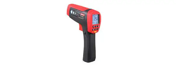
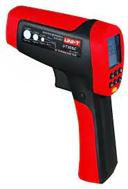
The Model UT305A/B/C and UT306A/B/C Infrared Thermometers (hereafter, the “Thermometer”) can determine the surface temperature by measuring the amount of infrared energy radiated by the target’s surface. They have different Distance to Spot(D:S) ratios and different temperature ranges, read the manual for details.
The Thermometer is a non-contact infrared instrument designed with low power consumption, which can make the measurements much faster and easier and meanwhile save you the amount of time from frequent battery replacement. It can be powered by the battery or the source with USB connected to. This Manual uses UT305A as illustration.
Safety Information
Warning
A warning identifies conditions and actions that pose hazards to the user. To avoid electrical shock or personal injury, follow these guidelines:
- Do not point the laser toward anyone’s eye or allow the laser to strike the eye from a reflective surface.
- Before using the Thermometer inspect the case. Do not use the Thermometer if it appears damaged. Look for cracks or missing plastic.
- Replace the battery as soon as the battery indicator appears.
- Do not use the Thermometer if it operates abnormally. Protection may be impaired. When in doubt, have the Thermometer serviced.
- Do not operate the Thermometer around explosive gas, vapor, or dust.
- To avoid a burn hazard, remember that highly reflective objects will often result in lower than actual temperature measurements.
- Do not use in a manner not specified by this manual or the protection supplied by the equipment may be impaired. To avoid damaging the thermometer or the equipment under test protect them from
- EMF (electromagnetic fields) from arc welders, induction heaters, etc; static electricity; thermal shock (caused by large or abrupt ambient temperature changes – all 30 minutes from the Thermometer to stabilize before use); placed on or near objects of high temperature.
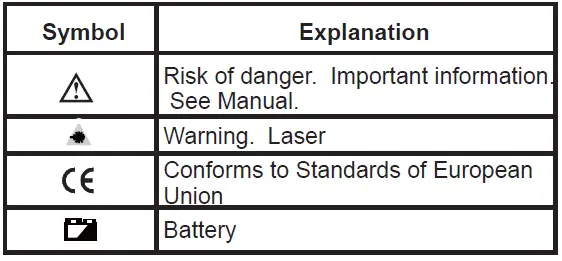
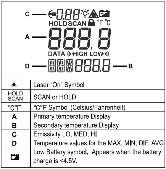
Table 1. Symbols
Features
The Thermometer includes:
- Single Laser Pointer USB-Powered
- Level 2 White Backlight (With USB connected, this feature will be on automatically).
- Current Temperature Plus MIN, MAX, DIF, AVG Display Functions
- Adjustable Emissivity
- Trigger Locked
- Selectable
- Tripod mount
- One 9V Battery
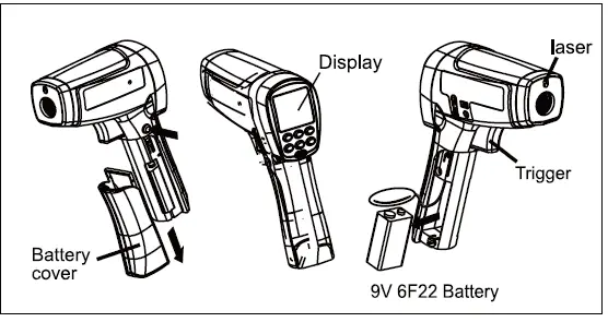
Display
The primary temperature display reports the current or last IR temperature reading until the 8-second hold time elapses. The secondary temperature display reports a choice of maximum, minimum, difference between maximum and minimum temperature or average value.
You can toggle through the maximum, minimum, difference and average IR temperatures anytime the display is on by pressing the yellow button. The MAX,MIN, DIF and AV temperatures are constantly calculated and updated when the trigger is pressed. After the trigger is released, the MAX, MIN, DIF and AV temperatures are held until the Thermometer is auto power off.
Notes
When the battery is low , appears on the display. The last selection (MAX/MIN/DIF/AVG) is maintained on the secondary display even after the Thermometer has been turned off, providing the batteries have not failed.
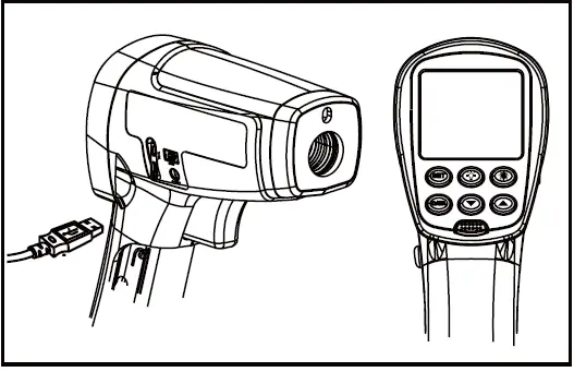
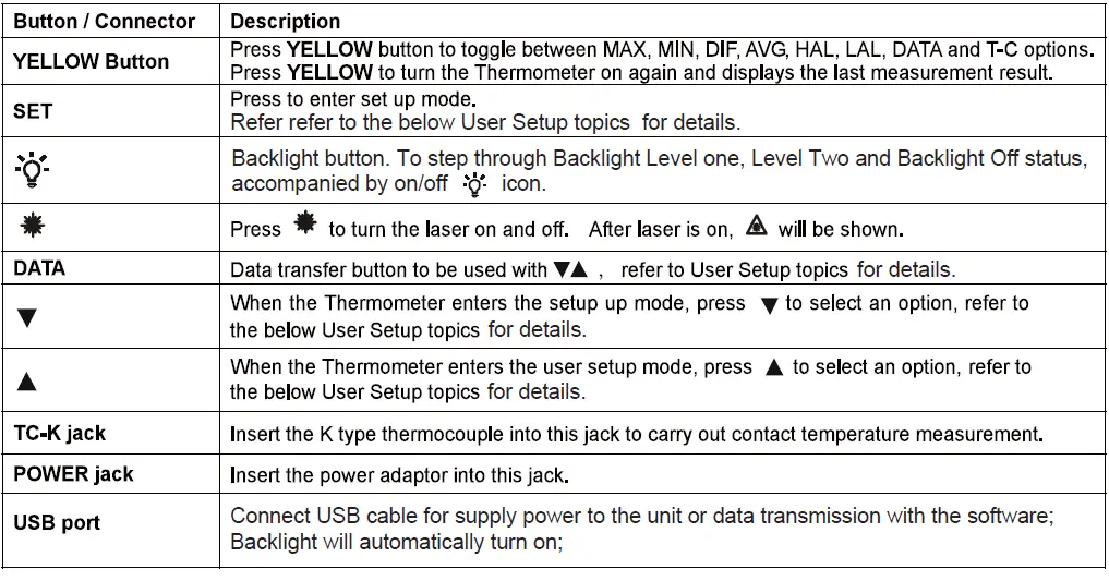
Buttons and Connector
How the Thermometer Works
Infrared thermometers measure the surface temperature of an opaque object. The Thermometer’s optics sense infrared energy, which is collected and focused onto a detector. The Thermometer’s electronics then translate the information into a displayed temperature reading which appears on the display. The laser is used for aiming purposes only.
Operating the Thermometer
The Thermometer turns on when you press the trigger. The Thermometer turns off when no activity is detected for 8 seconds. To measure temperature, aim the Thermometer at the target, pull and hold the trigger. Release the trigger to hold a temperature reading. Be sure to consider the distance-to-spot size ratio and filed of view. The laser is used for aiming only.
Locating a Hot or Cold Spot
To find a hot or cold spot, aim the Thermometer outside the target area. Then, slowly scan across the area with an up and down motion until you located the hot or cold spot. See Figure 5.
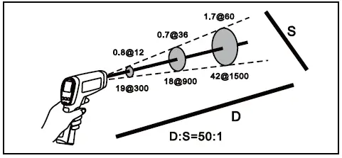
Distance and Spot Size
As the distance (D) from the target being measured increases, the spot size (S) of the area measured by the unit becomes larger. The spot size indicates 90% encircled energy. The maximum D:S is obtained when the Thermometer is 1000mm (100in) from the target resulting in a spot size of 20mm (2 in). See Figure 6.
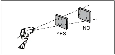
Field of View
Make sure that the target is larger than the spot size. The smaller the target, the closer you should be to it. See Figure 7.
Emissivity
Emissivity describes the energy-emitting characteristics of materials. Most organic materials and painted or oxidized surfaces have an emissivity of about 0.95. If possible, to compensate for inaccurate readings that may result from measuring shiny metal surfaces, cover the surface to be measured with masking tape or flat black paint (<150 / 302 ) and use the high emissivity setting. Allow time for the tape or paint to reach the same temperatures as the surface beneath it. Measure the temperature of the tape or painted surface.
If you cannot use paint or use tape, then you could improve the accuracy of your measurements with the emissivity selector. Even with an emissivity selector, it can be difficult to get a completely accurate infrared measurement of a target with a shiny or metallic surface.
User Setup
Press SET button to step through Emissivity Setup→ Trigger Lock→Switching → / Normal Measurement. Press YELLOW button to save and exit Setup.
Emissivity Setup
This feature is to change the value of emissivity. To adjust values for emissivity, follow the below procedure:
- Press SET to select emissivity set up, icon E=0 on the display is blinking.
- Press to increase the value by 0.01 or press and hold to access quick setting. The maximum value is 1.00.
- Press to decrease the value by 0.01 or press and hold to access quick setting. The minimum value is 0.10.
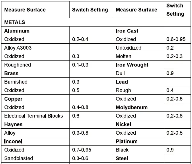
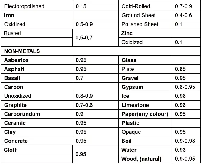
The Thermometer allows you to adjust the unit’s emissivity for the type of surface before measured. Refer to Table 2. But it is only a typical case. You could base on your own case and materials to have different setting.
Trigger Lock Setup.
This feature is to set trigger lock or unlock To lock or unlock the trigger, follow the below procedures:
- Press SET to select trigger lock setting, the is blinking.
- Press or to select ON or OFF.
When the trigger is locked, the Thermometer is on for continuous measurement, there is no need to pull the trigger. When the trigger is unlocked, user needs to pull the trigger for measurement. When you release the trigger, the Thermometer will keep hold the measurement result automatically.
Switching C/F
This feature is to select C or F.
- Press SET to choose C/F selection mode,
- Press or to select C or F.
HAL Setup
This feature is to set up the high limit. When carrying out measuring, the Thermometer beeps continuous if the temperature is over this limit.
- Press YELLOW button to toggle to HAL mode.
- Press to increase the value by 0.1 or press and hold to access quick setting until the maximum value is reached. The thermometer stops and beeps.
- Press to decrease the value by 0.1 or press and hold to access quick setting until the minimum value is reached or it lower than LAL value. The thermometer stops and beeps.
- Press SET to confirm this setting, the LCD displays
- This feature is not valid when carrying out measurement with TC-K type thermocouple
- HAL value cannot set below the LAL value.
LAL Setup
This feature is to set up the low limit. When carrying out measuring, the Thermometer beeps continuous if the temperature is below this limit.
- Press YELLOW button to toggle to LAL mode.
- Press to increase the value by 0.1 or press and hold to access quick setting until the maximum value is reached or higher than HAL value. The thermometer stops and beeps.
- Press to decrease the value by 0.1 or press and hold to access quick setting until the minimum value is reached. The thermometer stops and beeps.
- Press SET to confirm this setting, the LCD displays
- This feature is not valid when carrying out measurement with TC-K type thermocouple
- HAL value cannot set higher than the LAL value.
DATA
This feature is to store the data measuring under infrared mode.
- The maximum number of data to be stored is 99.
- When the storage is empty, it displays “— . —“
- Under non-measurement mode, press and hold DATA and for 8 seconds to clear the stored data, the Thermometer beeps.
- Under measurement mode, press YELLOW button to toggle to DATA mode.
- Press or to select the location of storing the data.
- Press DATA to store the value.
TC-K Thermocouple Measurement
This feature is to measure temperature with K type thermocouple.
- Press YELLOW button to toggle to T-C mode. The LCD display shows OL before the thermocouple is connected.
- Connect the K type thermocouple, press the trigger to start measuring. The LCD display shows the reading.
- Release the trigger, the reading is kept, LCD shows T-C. The temperature reading is shown on the bottom of right hand side.
HOLD
The display will remain activated 8 seconds after the trigger is released. HOLD appears in the upper middle of the display. When the trigger is pulled again, the Thermometer will begin measuring in the last function selected.
Typical Measurements
This section describes a variety of measurements often performed by technicians.
Operation Tips:
- User could select to turn on or off the backlight and laser whenever you are making readings with the Thermometer. But if you are using USB to power up the Thermometer, the two levels white colour backlight will be on automatically.
- Relatively high emissivity normally means emissivity setting of about 0.95.
- Relatively low emissivity normally means emissivity setting of about 0.30.
- When user cannot identify the emissivity of the object to be measured, user could cover the surface to be measured (temperature >150 ) with black electric tape (emissivity of about 0.95). Allow time for the tape to reach the same temperature as the object to be measured. Measure and record the temperature of the tape. Target the Thermometer to the object to be measured, adjust the emissivity setting to make it as the same temperature as the tape. At this time, the Thermometer emissivity setting is close to the emissivity of the object to be measured, the measurement could be started.
Testing Contactors (Starters)
- Press SET to select emissivity. Press / to select relatively low emissivity for bright contacts, or 0.7 mid level for darkened contacts.
- Press YELLOW button to select MAX.
- Measure line and load side of one pole without releasing trigger
- A temperature difference between the line and load sides of a pole indicate increased resistance of one point and a contactor may be failing.
Testing Enclosed Relays
- Press SET and then press / to set emissivity to relatively low for uninsulated connectors or relatively high for plastic encased relays or for bakelite enclosed relays or insulated connectors.
- Press YELLOW button to select MAX.
- Start to scan.
- Measure the relay casing, looking for hot spots.
- Measure electrical connections on relay terminals looking for hot spots.
Testing Fuses and Buss Connections
- Press SET and then press / to set emissivity to relatively high for paper-covered fuse body or insulated connections.
- Press YELLOW button to select MAX.
- Scan the paper-covered length of fuse.
- Without releasing the trigger, scan each fuse. Unequal temperatures between fuses may indicate voltage or amperage imbalance.
- Press SET and then press / to set emissivity to relatively low, for metal fuses and caps and insulated buss connections.
- Press YELLOW button to select MAX.
- Scan each end cap on each fuse/
Note
Unequal temperatures or a high temperature indicates loose or corroded connection through the fuse buss spring clip.
Testing Electrical Connections
- Press SET and then press / to set emissivity to relatively low for uninsulated connectors or buss connections or relatively high for insulated connections.
Note
Conductors are typically smaller than the Thermometer’s spot size. If the spot size is bigger than the connector, the temperature reading is the average within the spot. - Scan the conductor, moving toward direction of electrical connector (quick connect, wire nut, buss connection, or lug).
Scanning Walls for Air Leaks or Insulation Deficiencies
- Turn off heating, cooling, and blower.
- Press SET to select emissivity. Press / to select emissivity relatively high for painted surfaces or window surfaces.
- Press YELLOW button to select MIN when opposite side of wall is at lower temperature and or select MAX when opposite side of wall is at higher temperature.
- Measure an interior partition wall surface temperature. Do not release the trigger. Record this temperature as your baseline (or benchmark) for a “perfectly” insulated wall.
- Face the wall to be scanned. Stand 1.2m away to scan a 10cm spot on the wall.
- Scan horizontal rows of wall from top to bottom, or horizontal rows of ceiling from wall to wall. Look for greatest deviations from baseline temperature to identify problems. This completes the insulation test scan. Turn on the blower (no heat, no cooling) and retest. If test results with the blower on are different than results with the blower off, this may indicate air leaks in conditioned envelope walls. The air leaks are caused by duct leaks that create a pressure differential across the conditioned space envelope.
Testing Bearings
Warning
To avoid injury when testing bearings:
- Do not wear loose clothing, jewelry, or anything around neck when working around moving parts such as motors, belts, blower, and fans.
- Make sure an electrical disconnect is within reach and operating correctly and freely.
- Do not work alone.
Note
It works best to compare two similar motors operating similar loads.
- Press SET and then press / to select relatively high emissivity.
- Press YELLOW button to select MAX.
- Enable motor and allow it to reach steady-state operating temperatures.
- Disable the motor if possible.
- Measure the two motor bearing temperatures
- Compare the two motor-bearing temperatures. Unequal temperatures or a high temperature can indicate lubrication or other bearing problem that is resulting from excess friction.
- Repeat the sequence for the blower bearings.
Testing Belts and Sheaves
- Press SET and then press / to select relatively high emissivity.
- Press YELLOW button to select MAX.
- Enable the motor and allow it to reach steady-state operating temperatures.
- Aim the thermometer at the surface to be measured.
- Start recording temperature
- Slowly move the Thermometer up the belt toward second sheave.
- If belt is slipping, sheave temperature will be high from friction.
- If belt is slipping, belt temperature will remain high between sheaves.
- If belt is not slipping, belt temperature will reduce between sheaves.
- If inner surfaces of sheaves are not a true “V” shape, this indicates belt slippage and will continue to operate at elevated temperatures until sheave is replaced.
- Sheaves must be properly aligned (include “pitch & yaw”) for belt and sheaves to operate at appropriate temperatures. A straight edge or taut string, can be used to check alignments.
- Motor sheave should operate at a temperature consistent with blower sheaves.
- If motor sheave is at a higher temperature at motor shaft than at outer circumference, belt is probably not slipping.
- If outer circumference of sheave is at higher temperature than sheave at motor shaft, then belt is probably slipping and sheaves may be misaligned.
Checking Hydronic Radiant Heat Applications
Radiant heat tubes in the floor will normally run parallel to the outside walls. Starting at the floor wall juncture, scan parallel to the wall while moving into the room away from the wall. Parallel to the outside wall you should find parallel isothermal rows indicating the location of heat tubes below the surface. Perpendicular to the outside wall, you should find rising and falling temperatures at equal distances. High temperatures indicate you are scanning a heat tube beneath the floor surface, low falling temperatures indicate a space between the heat tubes.
- Press SET and then press / to select relatively high emissivity.
- Press YELLOW button to select MAX.
- To locate radiant heat tubes in floor, temporarily elevate the loop temperature to create hotter spots for identifying tubing runs.
- Before releasing trigger, press YELLOW button to toggle between MIN, MAX, DIF floor temperatures and record the temperature for future comparison and trending under similar conditions.
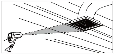
Measuring Grille, Register, or Diffuser Discharge Temperature
- Press SET and then press / to select relatively high emissivity.
- Aim the Thermometer at the discharge air grille, register, or diffuser.
- Measure discharge temperature.
- Release trigger to freeze the temperature reading for 8 seconds and record this temperature.
- Grille, register, or diffuser temperature should be equivalent to discharge temperature at the air handler.
Checking for Blockage in Air-To-Air Evaporators or Condensers
- Remove panels to gain access to coil return bends or hairpins.
- Press SET and then press / to select relatively high emissivity for copper tube.
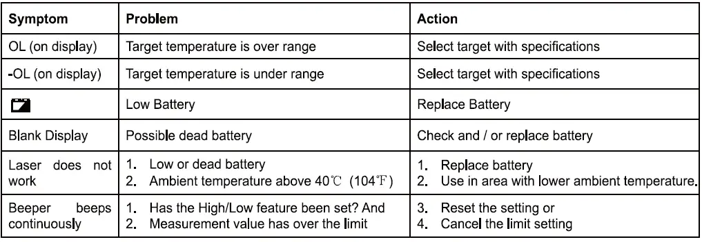
Troubleshooting