Lift Shift HHQD-5 Hydraulic Swivel Toe Jack
INTRODUCTION
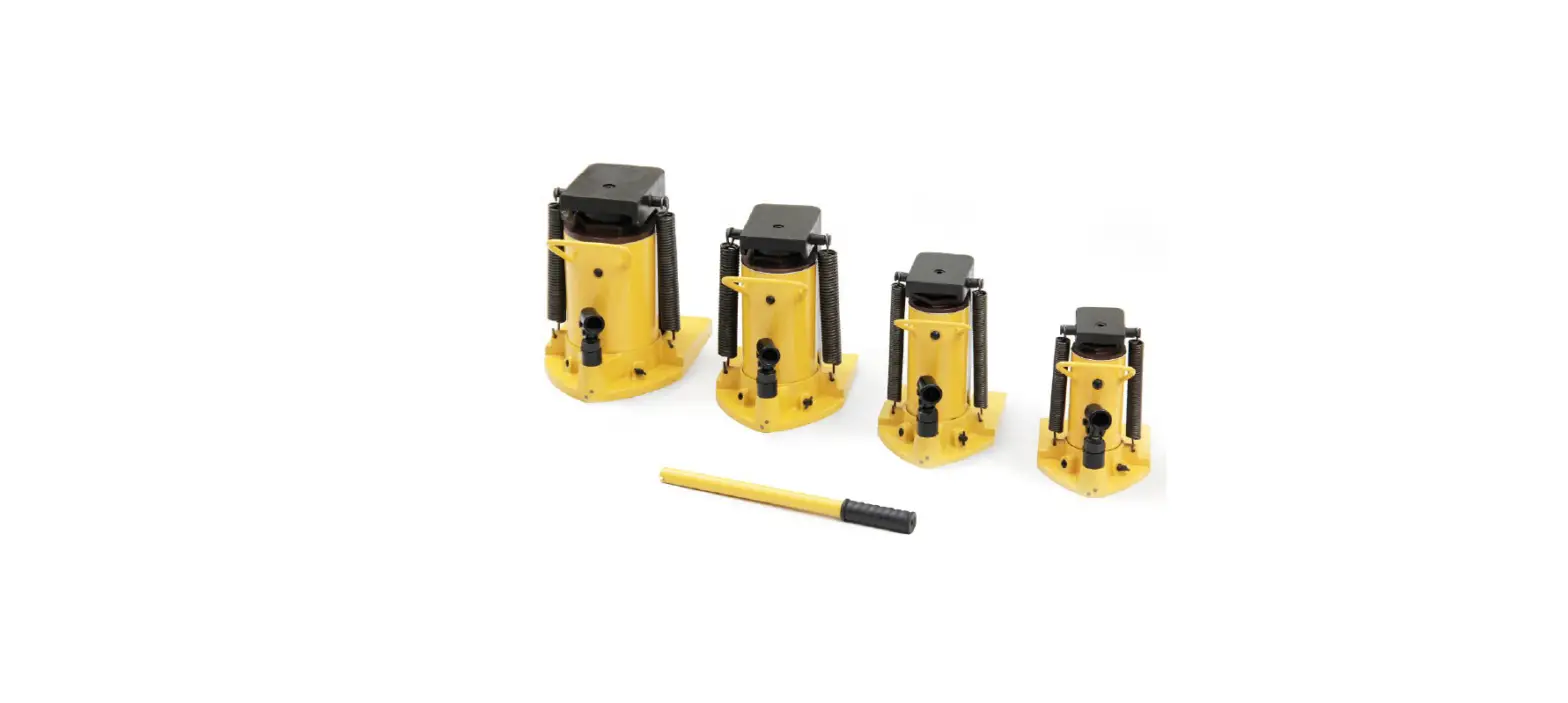
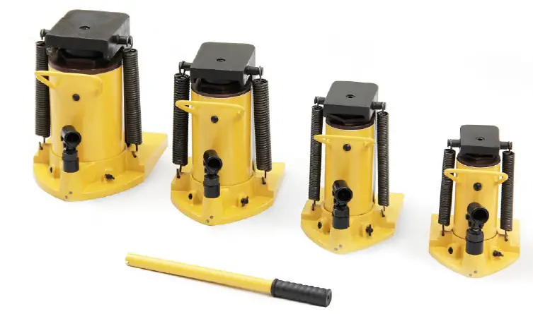
- Hydraulic toe jack with multi-function head and toe lifting mechanisms
- Quick, smooth effortless operation by hand
- Lifting points on the toe and head allow for a versatile lifting
- Ideal for lifting low-weight points and working in confined spaces
- Toe constructed from strong mold casted alloy steel with no welded or bent parts to weaken the material
- High-strength return spring enables rapid ram retraction
- Swiveling pump handle assembly allows the operator to access and pump the unit from a variety of positions
- Built-in safety valve prevents over-pressurization
- The internal overflow valve functions as a stroke limiter
- Convenient carry handle
SPECIFICATIONS
| Model Number: | HHQD-5 | HHQD-10 |
| Lifting Capacity (Toe): | 2.5 Tonne | 5 Tonne |
| Lifting Capacity (Head): | 5 Tonne | 10 Tonne |
| Stroke: | 120mm | 130mm |
| Closed Height: | 222mm | 265mm |
| Jaw Height: | 16mm | 18mm |
| Net Weight: | 12.1kg | 18.5kg |
| Model Number: | HHQD-20 | HHQD-30 |
| Lifting Capacity (Toe): | 10 Tonne | 15 Tonne |
| Lifting Capacity (Head): | 20 Tonne | 30 Tonne |
| Stroke: | 130mm | 140mm |
| Closed Height: | 285mm | 305mm |
| Jaw Height: | 20mm | 20mm |
| Net Weight: | 29kg | 43.4kg |
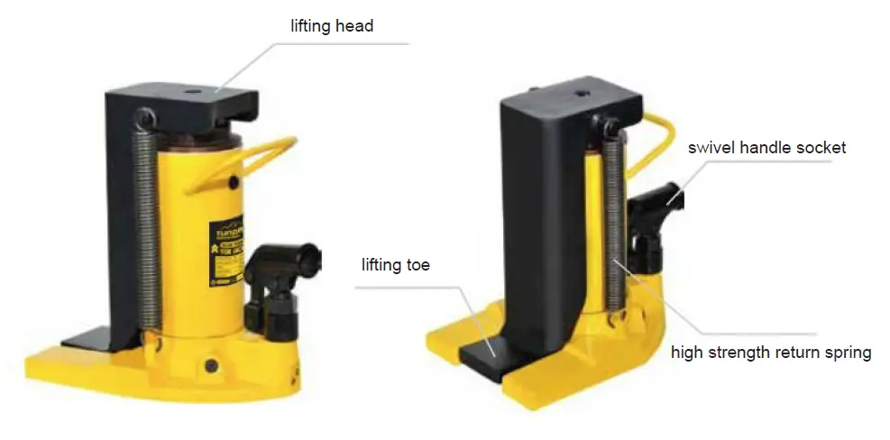
EQUIPMENT IDENTIFICATION
SAFETY GUIDELINES
- Read these instructions carefully before use and wear the appropriate safety equipment during operation.
- Inspect this equipment regularly and check for damage before use.
- Never use this equipment if any damage or fault is detected. Immediately repair or replace damaged parts.
- Only use Manufacturer’s original replacement parts when repairing the jack.
- The use of unapproved parts may be dangerous and will invalidate your warranty.
- Lubricate and clean the jack regularly to maintain the equipment and keep it in safe working condition.
- Use a qualified person to lubricate and maintain the jack. Only use hydraulic oil.
- Ensure the work area is clean, tidy, well lit and free from clutter. Keep children and animals away from the working environment.
- Always use the jack on solid, level ground, preferably concrete.
Avoid soft materials such as tarmacadam as the jack may sink and become unstable under load. - Do not modify jack in any way. Do not use the jack for any other purpose other than that for which it was designed.
- Keep hands etc. clear of moving parts during raising and lowering of the load.
- If being used to lift a vehicle, park the vehicle and apply hand brake. Switch off the engine and place chocks under the wheels.
- Ensure a minimum distance of 0.5m between load and static objects such as doors, walls, etc. to allow for tilting during jacking.
- Check that the lifting point is centred and stable on the jack saddle (off centre loads can slip).
- Always position jack so as to avoid operating it from under the load.
- Only use the jack for lifting only, this equipment is not designed to supporting the lifted load.
- Always use adequately rated mechanical supports.
- Never exceed the rated capacity of the jack and do not operate the jack beyond its maximum pump stroke.
- If lifting a vehicle, do not allow the vehicle to move, or try to start the engine, when the vehicle is jacked up.
- Do not jack a vehicle if it may result in the spillage of fuel, battery acid, or other dangerous substances.
- Do not place any part of your body under load whilst it is supported by the jack.
- Wait until adequately rated supports have been correctly positioned.
- Do not use jack to support extensions or cradles.
- Do not adjust the safety overload valve.
- Ensure there are no persons or obstructions beneath the load before lowering.
- Clean and stow the jack in a secure and dry environment with the ram in the down position after use.
- Never leave the ram extended.
OPERATING INSTRUCTIONS
Before Use:
Before using the jack, ensure that the hydraulic system is fully purged to eliminate any air that may have accumulated during transit:
- Fit jack handle over release valve and turn anti-clockwise to open the valve.
- Insert jack handle into the sleeve and pump several times to ensure full internal lubrication and to bleed any excess air from the system.
- Fit jack handle back over the release valve and turn clockwise to close.
Lifting:
- Always use the jack on solid, level ground, preferably concrete.
- Place either toe or head beneath load to be lifted, depending on the application and clearance available.
- If using the toe, ensure that it is inserted beneath the load fully to ensure maximum stability.
- Pump the handle up and down using full strokes until the required lifting height is achieved.
- If the jack becomes overloaded, the safety overload valve will open, and prevent the load from lifting any further.
MAINTENANCE
Important: Inspect this equipment regularly and check for damage before use.
- Never use this equipment if any damage or fault is detected. Immediately repair or replace damaged parts.
- Only use Manufacturer’s original replacement parts when repairing the jack.
- The use of unapproved parts may be dangerous and will invalidate your warranty.
- Do not use brake fluid or any fluid other than hydraulic jack fluid, as to do so may cause serious damage to the jack and will invalidate the warranty.
- Periodically check the pump piston and piston rod for signs of corrosion. Clean exposed areas with a clean oiled cloth.
Storage:
When the jack is not in use, the ram and piston must be placed in their lowest positions to minimise corrosion.
Lubrication:
- Remove the handle to render the jack inoperable and store in a secure dry environment.
- Keep the jack clean and lubricate all moving parts with acid free oil on a regular basis.
Checking Hydraulic Oil Level / Refilling Oil
- Fully lower the jack.
- Remove the filler plug.
- The correct oil level is indicated to the bottom of the filler opening.
- We recommend that you should replace the hydraulic oil after every year of extensive use. Drain the oil through the filler plug opening.
- Ensure that no dirt or debris is allowed to enter the jack or the fresh oil during this process.
- To replace the oil fill as required.
- Pump (the unloaded jack) 5 or 6 times to expel any excess air.
- Pump jack to full height and pour off excess oil before refitting the filler plug.
Note: Ensure waste oil is disposed of in accordance with local authority regulations.
De-commissioning:
Draw off the oil into an approved container and dispose of the jack and the oil according to local regulations.
TROUBLESHOOTING
| Problem | Possible Causes | Solution |
| Jack will not lift the load | 1. Jack has been overloaded 2. Low oil level 3. Release valve is open or only partially closed 4. Excess air in the system 5. Packing worn or defective | 1. Check and confirm jack has rated capacity for the load and application (head & toe capacity) 2. Top up hydraulic oil level 3. Check and close the release valve 4. Open release valve and air valve (if fitted) and pump the handle a few times to purge the air. Close the release valve & retry. 5. Contact the Seller or the nearest service center for advice. |
| Jack will not lift high enough or feels “spongy” | 1. Low oil level 2. Worn or damaged seals 3. Excess air in the system 4. Release valve is open or only partially closed | 1. Top up hydraulic oil level 2. Contact the Seller or the nearest service center for advice. 3. Open release valve and air valve (if fitted) and pump the handle a few times to purge the air. Close the release valve & retry. 4. Check and close the release valve |
| Jack lifts but will not hold the load | 1. Release valve is open or only partially closed 2. Excess air in the system 2. Worn or damaged seals | 1. Check and close the release valve 2. Open release valve and air valve (if fitted) and pump the handle a few times to purge the air. Close the release valve & retry. 3. Contact the Seller or the nearest service center for advice. |
| Jack will not lower completely | 1. Ram is damaged 2. Excess air in the system 3. Release valve is open or only partially closed | 1. Contact the Seller or the nearest service center for advice. 2. Open release valve and air valve (if fitted) and pump the handle a few times to purge the air. Close the release valve & retry. 3. Check and close the release valve |
PARTS DIAGRAM
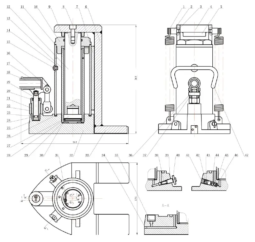
PARTS LIST
| # | Description | Qty | # | Description | Qty |
| 1. | Spring | 2 | 25. | Gasket | 1 |
| 2. | Spring Pin | 2 | 26. | Trapezoid sealing ring | 1 |
| 3. | Side Plate | 2 | 27. | Piston | 1 |
| 4. | Roof | 1 | 28. | Bowl shaped pad | 1 |
| 5. | Fix Ring | 1 | 29. | Trapezoid sealing ring | 1 |
| 6. | Vertical Plate | 1 | 30. | O-ring | 1 |
| 7. | Guide Plate | 1 | 31. | Steel ball retaining ring | 1 |
| 8. | Socket cap screw | 1 | 32. | Pedestal | 1 |
| 9. | O-ring | 1 | 33. | Plate | 1 |
| 10. | Top Cap | 1 | 34. | Screw | 2 |
| 11. | Backup ring | 1 | 35. | Steel ball | 3 |
| 12. | Piston Rod | 1 | 36. | Pin B8x28 | 3 |
| 13. | Cylinder | 1 | 37. | Pin 2×12 | 3 |
| 14. | Cover | 1 | 38. | Rectangular seal ring | 1 |
| 15. | Oil Plug | 1 | 39. | Oil return valve stem | 1 |
| 16. | Connecting Rod | 1 | 40. | Pin D4x22 | 1 |
| 17. | Handle Connector | 1 | 41. | Safety valve cover | 1 |
| 18. | Handle | 1 | 42. | Safety valve stem | 1 |
| 19. | Pump Core | 1 | 43. | O-ring | 1 |
| 20. | J Shape Dustproof Ring | 1 | 44. | Safety valve spring | 1 |
| 21. | Pump Body | 1 | 45. | Head | 1 |
| 22. | Connector | 1 | 46. | Steel ball | 1 |
| 23. | Retaining Ring | 1 | 47 | Handle | 1 |
| 24. | O-ring | 1 |


