
![]() IMX12-DI01-2S-2T-0 Isolating Switching Amplifier
IMX12-DI01-2S-2T-0 Isolating Switching Amplifier
User Guide
Other documents
Besides this document the following material can be found on the Internet at www.turck.com:
- Datasheet
- Instructions for use
- Safety manual
- Device approvals
- EU Declaration of Conformity (current version)
For your safety
Intended use
These devices are designed solely for use in industrial areas.
The IM12-DI01… switching amplifiers transfer galvanically isolated binary signals. The devices are also suitable for operation in zone 2. Sensors according to EN 60947‐5‐6 (NAMUR) or potential-free contacts can be connected to the devices. The devices also enable the creation of safety-related applications up to and including SIL2 (high demand and low demand as per IEC 61508; hardware fault tolerance HFT = 0).![]() DANGER
DANGER
These instructions do not provide any information on use in safety-related applications.
Danger to life due to misuse!
- When using the device in safety-related systems: Observe the instructions contained in the associated safety manual without fail.
The devices must only be used as described in these instructions. Any other use is not in accordance with the intended use. Turck accepts no liability for any resulting damage.
General safety instructions
- The device must only be fitted, installed, operated, parameterized, and maintained by trained and qualified personnel.
- The devices only meet the EMC requirements for industrial areas and are not suitable for use in residential areas.
Notes on Ex protection
- Only use the device in Ex areas when installed in the appropriate protective enclosure.
- Observe national and international regulations for explosion protection.
- When using the device in Ex circuits, the user must also have additional knowledge of explosion protection (EN 60079-14, etc.).
- Only use the device within the permissible operating and ambient conditions (see certification data and Ex approval specifications).
ATEX approval requirements for use in Zone 2
- Install the device in an enclosure according to EN 60079-0 with a degree of protection of at least IP54 per IEC/EN 60529.
- Install the device only in areas with a pollution degree of no more than 2.
- Connect and disconnect circuits only when no voltage is present.
- Press the DIP switches only if no explosive atmosphere is present.
Product description
Device overview
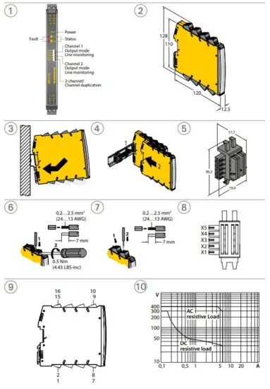
See fig. 1: Front view, fig. 2: Dimensions, fig. 5: Power-Bridge connector, fig. 10: Relay load curve Functions and operating modes
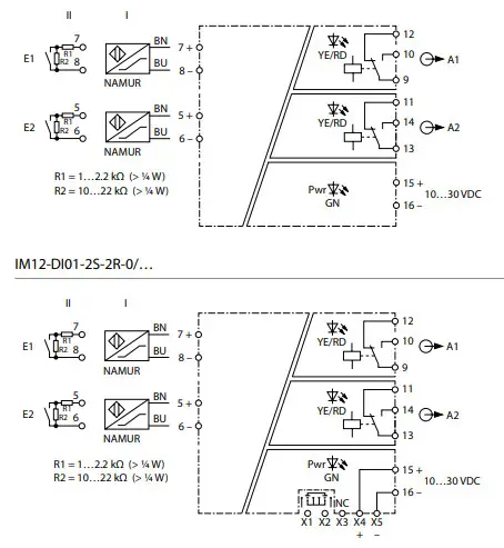
The IM12-DI01…-2R switching amplifiers are equipped with two relay outputs (changeover) and transmit galvanically isolated input signals from the sensors or the potential-free contacts.
Depending on the respective input level, input signals are interpreted as low or high levels and made available as a corresponding output signal. The devices with a Power-Bridge connector also offer the option of transmitting a collective fault message.
Installing
![]() DANGER
DANGER
Potentially explosive atmosphere
Risk of explosion through spark ignition!
When used in zone 2:
- Mounting and connection are only permissible if there is no potentially explosive atmosphere present.
- Install the device in an enclosure in accordance with EN 60079-0 with a degree of protection of at least IP54.
- When installing, ensure that the permissible operating temperature for the device will not be exceeded in the enclosure, even in unfavorable ambient conditions.
Mounting on DIN Rail without a Power-Bridge connector
- Fasten the device as shown in fig. 3.
- Mounting on DIN Rail with a Power-Bridge connector
- Mount the device as shown in fig. 4.
Connection
Refer to fig. 8 and 9 for the numbering of the terminals.
- Connect the devices with screw terminals as shown in fig. 6.
- Connect the devices with cage clamp terminals as shown in fig. 7.
Commissioning
The device automatically becomes operational once the cables are connected and the power supply is switched on.
Operation
LEDs
| Color | Meaning |
| Green | Device is operational |
| Yellow | Output A1 is ON (high signal) |
| Off | Output A1 is OFF (low signal) |
| Red flashing (NE44) | Wire break/short circuit at input E1 |
| Off | No error |
| Yellow | Output A2 is ON (high level) |
| Off | Output A2 is OFF (low level) |
| Red flashing (NE44) | Wire break/short circuit at input E2 |
| Off | No error |
With Power-Bridge applications: When the power supply is switched on, the group fault output is energized momentarily for 120 ms and the red LEDs are lit.
Setting and parameterization
Setting via DIP switches
| DIP switch | Meaning |
| NC/NO1 | Channel 1: Operating mode setting: Closed current (NC)/ working current (NO) |
| LM/off1 | Channel 1: switching on/switching offline monitoring (LM) |
| NC/NO2 | Channel 2: Operating mode setting: Closed current (NC)/working current (NO) |
| LM/off2 | Channel 2: switching on/switching offline monitoring (LM) |
| 22-Dec | Configuring output A2: two-channel operation with the transmission of the input signal E2 to output A2 (22)/one-channel operation with signal duplication of input E1 (12) |
Repair
The device must be decommissioned if it is faulty. The device may only be repaired by Turck.
Refer to our return acceptance conditions when returning the device to Turck.
Disposal![]() The devices must be disposed of correctly and must not be included in general household garbage.
The devices must be disposed of correctly and must not be included in general household garbage.
Wiring Diagrams
EU Declaration of Conformity
Certification Data
Approvals and markings
| Approvals | Marking parts in acc. with ATEX-directive | EN 60079-0/-15 |
| ATEX | Ex ec nC IIC T4 Gc |
![]() Certificate number:
Certificate number:
TURCK Ex-17004HX
Permissible ambient temperature range Tamb: -25…+70 °C
Electrical data
| Supply circuit non intrinsically safe | Contacts 15+ and 16- resp. Contacts X4+ and X5- (power bridge) | U = 10…30 VDC |
| Output circuits – relays non intrinsically safe | Make contacts (n. o.): Contacts 9 and 10 Contacts 13 and 14 Break contacts (n. c.): Contacts 9 and 12 Contacts 13 and 11 Contact X1(X2) (Failure signal output) | per relay contact: U = 250 VAC, I = 2 A, S = 500 VA U = 125 VDC, I = 0.5 A resp. U = 30 VDC, I = 2 A P = 60 W |
Hans Turck GmbH & Co. KG | Witzlebenstraße 7, 45472 Mülheim an der Ruhr, Germany | Tel. +49 208 4952-0 | Fax +49 208 4952-264 | [email protected] | www.turck.com
Additional information see![]()
 https://www.turck.de/en/search.php?q_simple=IM12-DI01*2R


