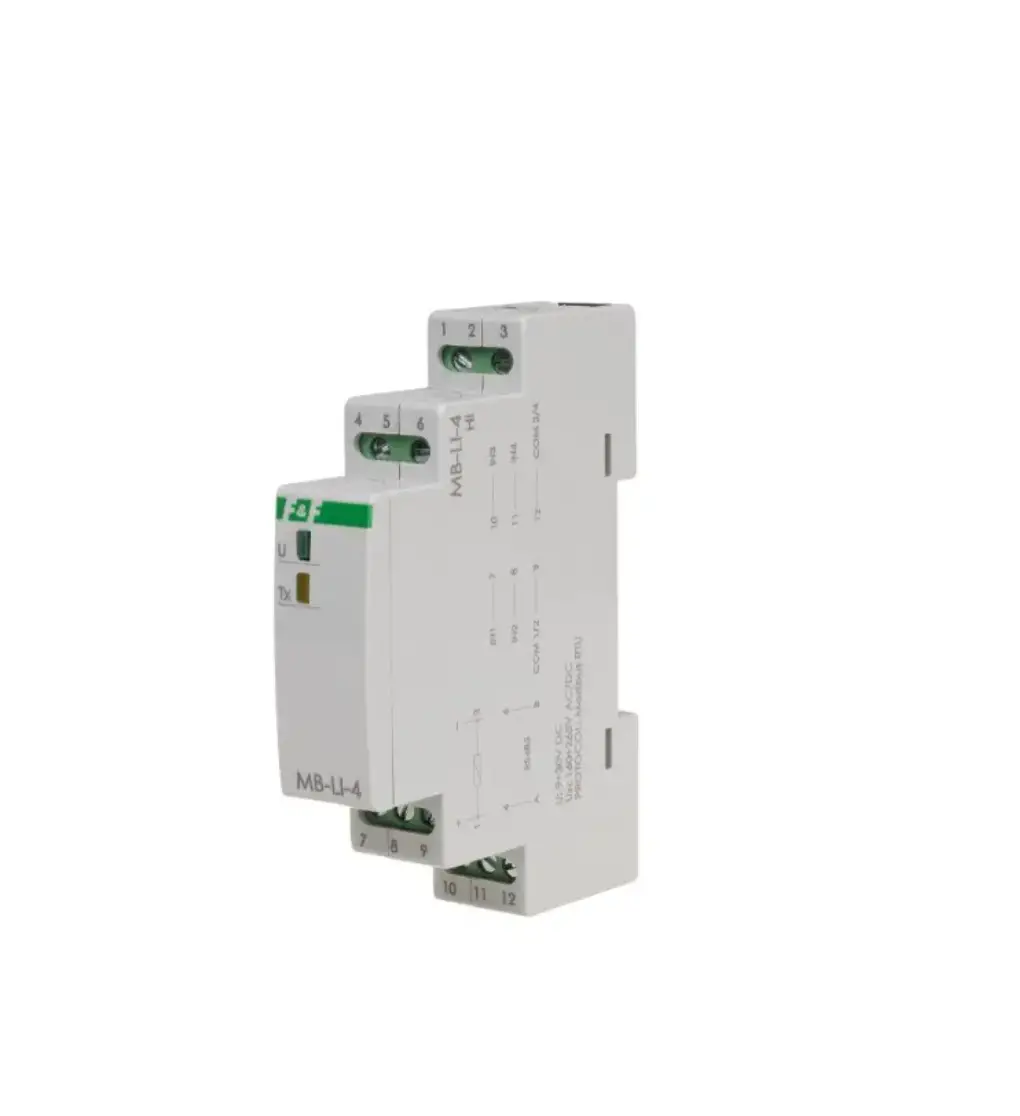
F F MB-LI-4 Lo 4-channel Pulse Counter
MB-LI-4 Lo Pulse counter, 4-channel, with Modbus RTU output
Do not dispose of this device in the trash along with other waste! According to the Law on Waste, electro coming from households free of change and can give any amount to up to that end point of collection, as well as to store the occasion of the purchase of new equipment (in accordance with the principle of old-for-new, regardless of brand). Electro thrown in the trash or abandoned in nature, pose a threat to the environment and human health.
Purpose
The MB-LI-4 pulse counter is used for counting the AC/DC signals generated by external devices to determine the number of completed work cycles and for exchanging the data via RS-485 port in accordance with the Modbus RTU protocol.
Functions
- 4 independent counters;
- Counter input designed to work with AC/DC signals;
- Factor adjustment (a floating-point value);
- Rescaled value (Number of pulses × factor);
- Selecting a mode of state 1 trigger: high or low voltage;
- Selecting an input pulse edge (leading or trailing);
- Frequency filter that allows you to limit the maximum frequency of counted pulses (to eliminate interferences on the input of the counter);
- Memory of counter status after power failure;
- Digital input.
Functioning
The MB-LI-4 module is a four-channel one-way counter. Each channel is independent and counts the impulses in accordance with individual settings.
The results are presented in the form of a Number of pulses and rescaled value in a range from 0 to ~4,29 billion. Reading of the counter can be reset independently for each channel. Once the maximum Number of pulses (overflow) is reached, counter automatically resets and counts from 0.
The module has configurable options of counting pulses with low (0 V) or high (V+) signal and with leading or trailing edge.
In addition, counting input can be used as a DI digital input with the ability to read its state.
Reading the values of counted pulses, a rescaled value, adjustment of all counting parameters, communication and data exchange is carried out via RS-485 port using Modbus RTU communication protocol. Power is indicated by a green LED “U” light. Correct data exchange between the module and other device is indicated by the LED yellow “Tx” light.
Mounting
![]() The use of anti-interference and surge filters (such as OP-230) is recommended.
The use of anti-interference and surge filters (such as OP-230) is recommended.
![]() It is recommended to use shielded twisted-pair cables to connect the module to another device.
It is recommended to use shielded twisted-pair cables to connect the module to another device.
![]() When using shielded cables, ground the screens only on one side and as close to the device as possible.
When using shielded cables, ground the screens only on one side and as close to the device as possible.
![]() Do not route signal cables in parallel in close proximity to high and medium voltage lines.
Do not route signal cables in parallel in close proximity to high and medium voltage lines.
![]() Do not install the module in the immediate vicinity of high-power electric receivers, electromagnetic measuring instruments, phase power control devices and other devices that may cause interference.
Do not install the module in the immediate vicinity of high-power electric receivers, electromagnetic measuring instruments, phase power control devices and other devices that may cause interference.
- Before installing the module, set the selected Modbus communication parameters and measurement options.
- Disconnect the power supply in distribution box.
- Install the module on the rail.
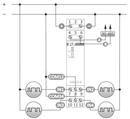
- Connect the module power supply to terminals 1-3 as indicated.
- Connect the A-B signal output (RS-485 port) to the Master device output.
- Connect the signal wires to the counter inputs according to the selected trigger option (low or high signal).
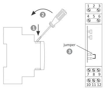
Wiring diagram
Terminal description
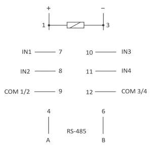
1-3 9÷30 V DC power supply
4-6 RS-485 serial port
7 IN1 counter input
8 IN2 counter input
9 COM input (common) for IN1 and IN2
10 IN3 counter input
11 IN4 counter input
12 COM input (common) for IN3 and IN4
Communication settings reset
A configuration jumper is available under the module casing. Starting the controller with the jumper closed restores the factory settings of the communication parameters. To do this, remove the casing of the module and put the jumper on both pins. After the reset is done, remove the jumper.
Examples of connection of counter and digital inputs
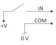
Triggering level high voltage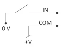
Triggering level low voltage
Security
- Galvanic isolation between the IN…, COM… contacts and the rest of the circuit (min. 2.5 kV). and the rest of the system (min. 2.5 kV).
- No galvanic isolation between module power supply and RS485 lines.
- Overcurrent protection for power supply and communication inputs (up to a maximum of 60 V DC) with automatic return function.
![]() An external control voltage is needed to trigger the input in any case. If the module’s supply voltage is used for this, the galvanic separation between the control inputs and the power supply and communication is lost.
An external control voltage is needed to trigger the input in any case. If the module’s supply voltage is used for this, the galvanic separation between the control inputs and the power supply and communication is lost.
Modbus RTU protocol parameters
Communication parameters
| Protocole | Modbus RTU |
| Operating mode | Slave |
| Port settings (factory settings) | Number of bits per second: 1200, 2400, 4800, 9600, 19200, 38400, 57600, 115200 Data bits: 8 Parity: NONE, EVEN, ODD Start bits: 1 Stop bits: 1/1,5/2 |
| Network address range (factory settings) | 1÷245 (1) |
| Command codes | 1: Read inputs status (0×01 – Read Coils) 3: Read the values of a group of registers (0×03 – Read Holding Register) 6: Set the value of a single register (0×06) – Write Single Register) |
| Max. frequency of queries | 15 Hz |
Communication registers
Address | Description | Function | Type | atr. |
| 256 | Read current and write new base address: 1÷245 | 03 06 | Int | R/W |
| 257 | Read current and write the baud rate: 0:1200/1:2400/ 2:4800/3:9600/4:19200/ 5:38400/6:57600/7:115200 | 03 06 | Int | R/W |
| 258 | Read current and write new parity value: 0:NONE/1:EVEN/2:ODD | 03 06 | Int | R/W |
| 259 | Read current and write new number of stop bits: 0:1 bit/1:1,5 bita/2:2 bity | 03 06 | Int | R/W |
| 260 | Restore the factory settings: Set the value 1. | 06 | Int | W |
| Note! Changes in communication parameters (baud rate, number of stop bits, parity) are only taken into account only after the power is restarted. | ||||
| 1024 ÷ 1025 | Module working time [s] R1024×256²+R102 | 03 | Int | R |
| 1026 ÷ 1027 | Serial number R1026×256²+R1027 | 03 | Int | R |
| 1028 | Production date: 5 bits – day; 4 bits – month; 7 bits – year (without 2000) | 03 | Int | R |
| 1029 | Software version | 03 | Int | R |
| 1030 | Execution: 0 – Lo; 1 – Hi | 03 | Int | R |
| 1031 ÷ 1035 | Identifier: F& | F | MB | -4 | LI | 03 | Int | R |
| 1039 | Configuration jumper: 0 – open; 1 – close | 03 | Int | R |
| Converter does not support broadcast commands (address 0) | ||||
Digital input registers
Address | Description | func. | Type | Atr |
| 0 | Read inputs status: 0/1 – 4 bits (e.g. 1001) Order: | In4 | In3 | In2 | In1 | | 01 | Int | R |
| 16 | In1: Input status 0/1 | 03 | Int | R |
| 32 | In2: Input status 0/1 | 03 | Int | R |
| 48 | In3: Input status 0/1 | 03 | Int | R |
| 64 | In4: Input status 0/1 | 03 | Int | R |
Counters registers
| Address | Description | Func | Type | atr. |
| 17÷18 | In1: Number of pulses R18×256²+R17 | 03 | Int | R |
| 33÷34 | In2: Number of pulses R34×256²+R33 | 03 | Int | R |
| 49÷50 | In3: Number of pulses R50×256²+R49 | 03 | Int | R |
| 65÷66 | In4: Number of pulses R66×256²+R65 | 03 | Int | R |
| S | S | S | S | s |
| 19÷20 | In1: Scaled value | 03 | Float | R |
| 21÷22 | In1: Scaled value – integer part | 03 | Int | R |
| 23÷24 | In1: Scaled value – fractional part: 6 digits ×0.000001 (250000 -> 0.25) | 03 | Int | R |
| 31 | In1: Counter reset. Enter value 0. | 06 | Int | W |
| 35÷36 | In2: Scaled value | 03 | Float | R |
| 37÷38 | In2: Scaled value – integer part | 03 | Int | R |
| 39÷40 | In2: Scaled value – fractional part: 6 digits ×0.000001 (250000 -> 0.25) | 03 | Int | R |
| 47 | In2: Counter reset. Enter value 0. | 06 | Int | W |
| 51÷52 | In3: Scaled value | 03 | Float | R |
| 53÷54 | In3: Scaled value – integer part | 03 | Int | R |
| 55÷56 | In3: Scaled value – fractional part: 6 digits ×0.000001 (250000 -> 0.25) | 03 | Int | R |
| 63 | In3: Counter reset. Enter value 0 | 06 | Int | W |
| 67÷68 | In4: Scaled value | 03 | Float | R |
| 69÷70 | In4: Scaled value – integer part | 03 | Int | R |
| 71÷72 | In4: Scaled value – fractional part: 6 digits ×0.000001 (250000 -> 0.25) | 03 | Int | R |
| 79 | In4: Counter reset. Enter value 0. | 06 | Int | W |
| S | S | S | S | S |
| 512 | In1: Pulse time minimum [ms]. Range 1÷15000. | 03 06 | Int | R/W |
| 513 | In1: Logic. 0: Falling slope 1: Rising slope | 03 06 | Int | R/W |
Configuration registers
| address | description | func | type | atr. |
| 514 | In1: Multipier. Range 1÷10000. | 03 06 | int | R/W |
| 515 | In1: Divisor. Range 1÷10000. | 03 06 | int | R/W |
| 528 | In2: Pulse time minimum [ms]. Range 1÷15000. | 03 06 | int | R/W |
| 529 | In2: Logic. 0: Falling slope 1: Rising slope | 03 06 | int | R/W |
| 530 | In2: Multipier. Range 1÷10000. | 03 06 | int | R/W |
| 531 I | In2: Divisor. Range 1÷10000. | 03 06 | int | R/W |
| 544 | In3: Pulse time minimum [ms]. Range 1÷15000. | 03 06 | int | R/W |
| 545 | In3: Logic. 0: Falling slope 1: Rising slope | 03 06 | int | R/W |
| 546 | In3: Multiplier. Range 1÷10000 | 03 06 | int | R/W |
| 547 | In3: Divisor. Range 1÷10000. | 03 06 | int | R/W |
| 560 | In4: Pulse time minimum [ms]. Range 1÷15000. | 03 06 | int | R/W |
| 561 | In4: Logic. 0: Falling slope 1: Rising slope | 03 06 | int | R/W |
| 562 | In4: Multiplier. Range 1÷10000. | 03 06 | int | R/W |
| 563 | In4: Divisor. Range 1÷10000. | 03 06 | int | R/W |
The ratio setting for the scaled value is the result of multiplying and dividing the set values of the registers (e.g. for In1, registers R514 and R515) Example:
Factor 2: multiplier =2; divisor=1 (2/1=2)
Factor 1.68: multiplier =168; divisor=100 (168/100=1.68)
Factor 0.68: multiplier =68; divisor=100 (68/100=0.68)
Default values:
logic = 1; pulse time = 5 ms; multiplier = 1; divisor = 1
Technical data
| power supply | 9÷30 V DC |
| number of counting inputs | 4 |
| counting input voltage | 6÷30 V AC/DC |
| maximum counting frequency | 100 Hz |
| maximum number of pulses | 232 (4.294.967.295) |
| input circuit impedance | ≥10 kΩ |
| port | RS-485 |
| communication protocol | Modbus RTU |
| operating mode | Slave |
| power indication | green LED |
| communication indication parametry komunikacji | yellow LED |
| baud rate (adjustable) | 1200÷115200 bit/s |
| data bits | 8 |
| stop bits | 1/1.5/2 |
| parity bit | EVEN/ODD/NONE |
| address | 1÷247 |
| power consumption | 0.3 W |
| working temperature | -20÷50°C |
| terminal | 2.5 mm² screw terminals |
| tightening torque | 0.4 Nm |
| dimensions | 1 module (18 mm) |
| mounting | on TH-35 rail |
| ingress protection | IP20 |
Warranty
The F&F products are covered by a warranty of the 24 months from the date of purchase. Effective only with proof of purchase. Contact your dealer or directly with us.
CE declaration
F&F Filipowski sp. j. declares that the device is in conformity with the essential requirements of The Low Voltage Directive (LVD) 2014/35/EU and the Electromagnetic Compatibility (EMC) Directive 2014/30/UE.
The CE Declaration of Conformity, along with the references to the standards in relation to which conformity is declared, can be found at www.fif.com.pl on the product page.