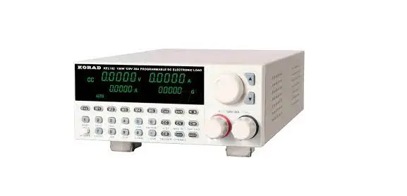
KORAD KEL102 DC Electronic Load
SAFETY INSTRUCTION
Safety Guidelines
- Do not block or obstruct the cooling fan vent opening
- Avoid severe impacts or rough handling that leads to damage.
- Do not discharge static electricity.
- Do not disassenble unless you are qualified as service personnel
ACINPUT
- AC I nut Voltage: 110V / 120V / 220V / 230V, 50 / 60 Hz
- Connect the protective grounding conductor of the AC power cord to an earth ground, to avoid electrical shock.
Operation Environment
- Location: Indoor, no direct sunlight, dust free, no conductive pollution
- Relative Humidity:< 80%
- Altitude:< 2000m
- Temperature: 0-40°C
Storage environment
- Location: Indoor
- Relative Humidity:< 70%
- Temperature: -10-70°C
FUSE
| Model | 110V/120V | 220V/230V |
| KEL102 | Tl.25A/250V(20X5mm) | T0.5A/250V(20x5mm) |
| KEL103 | Tl.25A/250V(20X5mm) | T0.5A/250V(20x5mm) |
- To ensure fire protection,replace the fuse only with the specified type and rating.
- Disconnect the power cord before fuse replacement.
- Make sure the cause of fuse blowout is confirmde before fuse replacemen
Introduction
KEL series (1sow~3oow), single-channel programmable DC electronic loads, are designed for middle & high-end applications. They can be offered as multiple solutions according to customer’s need. The online voltage measurements and adjustments or simulating short circuit test using the simple keypad on the front panel, can be used by the end users. KEL series DC loads are a versatile instrument for static and dynamic testing of power supplies, batteries, DC – DC converters, and battery chargers, which provides users the best testing solution.
Main Features
- Highlight LED display
- 5-digit display, and accurate outputs
- Resolution of voltage and current: 0.1 mV / 0.1 mA
- Over-voltage Protection
- 100 groups of memories for fast recall
- Four working modes: CV/CC/CR/CP
- Remote Compensation Function
- Battery Test Function
- Keyboard Lock
- Power off memory function
- Short-circuit function
- External Trigger Function
- Setting Function of Baud Rate
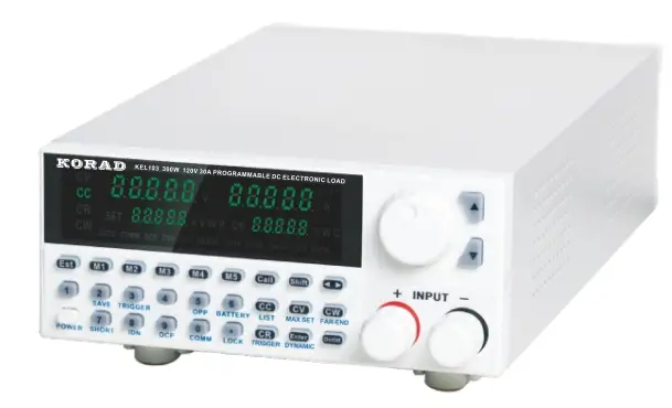
Front Panel Overview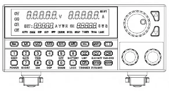
Rear Panel Overview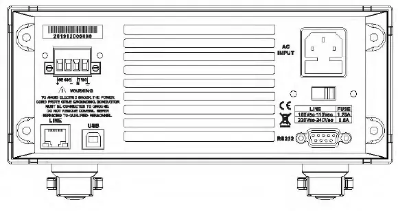
Operation
Keyboard Operation
- Esc: Cancel key which can return to the initial mode.
- Ml-MS: quickly recalling the Ml-MS stored value oft he steady state.
- Recall: Recall Key, such as, recalling the steady storage with Call+2.
- Shift: Setting or Storage Function Keys, such as storing the stationary content with Shift+2.
- Left-Rotating Key, moving to where needs to be adjusted and will flash.
- 0-9 Entering numbers.
- CC-Constant Current Mode Button.
- CC-Constant Voltage Mode Button.
- CW-Constant Power Mode Button.
- CR-Constant Resistance Mode Button.
- Confirmation Button.
- On/Off: Turning On/Off the load output.
- A.-Adjusting the number or selecting add.
- T-Adjusting the number or selecting subtract.
- Knob: Adjusting the number or selecting it.
Setting the maximum value of load
Description: Setting low voltage (18V), low current (3A) and below them the alwracy will be improved. Method of operation: Taking the max current 3A, max voltage 18V an max power 100W for example, the max resistance is l000ohms.
| Procedures | Operation | Description | Device Displays | |||
| 1 | Press |
II | + | ,, to operate | o.oooov SE T:30 .000 A | 0.000A 00000G |
| 2 | Setting the max current value and then press 11 “ | o.oooov SE T:3.0000 A | 0.000A 00000G | |||
| 3 | Press” II to operate | 0.0000V 0.000A SET: 120.00V 00000G |
| 4 | Setting the max voltage value and then press” “ | 0.0000V 0.000A SET:18.000V 00000G |
| 5 | Press” ” to operate | 0.0000V 0.000A SET:300.00W 00000G |
| 6 | Setting the max power value and then press” 11 | o.oooov 0.000A SET:100 . 00W 00000G |
| 7 | Press” ” to operate | 0.0000V 0.000A SET:7500.0R 00000G |
| 8 | Setting the max resistance value and then press” 11 | 0.0000V 0.000A SET:1000.0R 00000G |
| 9 | After the setting is finished, press {I rm II to exit . | The steady-mode status is displayed. |
The Operation Function of Steady State
Note: The electronic load can work in the following 4 steady-state modes.
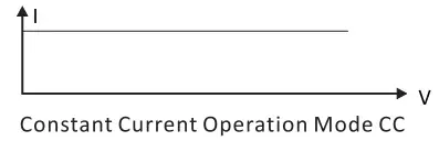
Constant Current Operation Mode CC
Note: In constant current mode, the load makes the tested equipment on the set voltage no matter how the input voltage changes.
Operation Method:
- Press the CC button on the keyboard to enter constant current operation mode.
- Setting the desired constant current through the keyboard.
- Turn on the ON/OFF button to start the electronic load. Load Current

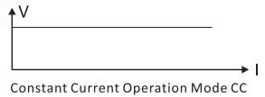
Constant Voltage Operation Mode CV
Note: In constant voltage mode, the load makes the tested equipment on the set voltage no matter how the input current changes.
Operation Method:
- Press the CV button on the keyboard to enter constant voltage operation mode.
- Setting the desired constant voltage through the keyboard.
- Turn on the ON/OFF button to start the electronic load. Load Voltage

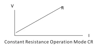
Constant Resistance Operation Mode CR
Note: In constant resistance mode, the load makes the tested equipment on the set resistance no matter how the input voltage and current change.
- Press the CR button on the keyboard to enter constant resistance operation mode.
- Setting the desired constant resistance through the keyboard.
- Turn on the ON/OFF button to start the electronic load.

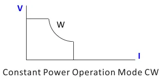
Constant Power Operation Mode CW
Note: In constant power mode, the load makes the tested equipment on the set resistance no matter how the input voltage and current change.
Operation Method:
- Press the CW button on the keyboard to enter constant power operation mode.
- Setting the desired constant power through the keyboard.
- Turn on the ON/OFF button to start the electronic load.

The Storage Function of Steady State and Recalling
Note: The load can save and recall 100 sets of stationary setting values. And to set the values, the number keys, knob and up & down buttons all can be used.
Storage function
Operation Method: Taking 10.000V stored to 99 as example.
| Procedures | Operation Description | Device Displays |
| 1 | Setting the steady state value to be stored{l0.000V) | 0.0000V 0.0000A 10.000V 00000G |
| 2 | Press” + “to enter the memory function. | 0.0000V 0.0000A 10.000V 00001G |
| 3 | Using the button input or the knob to 99 and then press ENTER to store | 0.0000V 0.0000A 10.000V 00001G |
Recall Function
Operation method: taking recalling the stored steady-state value in 99 As example.
| Procedures | Operation Description | Device Displays | |||
| 1 | Press” recall function | “to | enter the | 0.0Q00V lQ.Q00V | 0.0000A 0Q0Q0G |
| 2 | Using the button input or the knob to 99 and then press ENTER to store | 0.QQQ0V 10.000V | 0.Q0Q0A 00099G | ||
Ml-MS Fast Recall and Storage Function
Ml-MS Fast Recall Function
Note: By pressing Ml-MS, the steady state content stored in Ml-MS can be quickly recalled.
Ml-MS Fast Storage Function
Note: You can change the content of Ml-MS by selecting Ml-MS button; and then press the currently selected Ml-MS button to fast save the value to the currently selected M key. For example, the previous content of Ml is CV+lS.00lV and now needing to modify as CV+l4.000V, you can press Ml to recall the content and then modify to 14.000V through rotating the knob andthen pressing the number keys to select the value you want. After
that, press Ml again to save it in Ml.
Short Circuit Function
Note: the load will make the tested equipment output the max current.
Operation Method:
| Procedures | Operation Description | Device Displays |
| 1 | Press II + ,, to enter the short circuit testing mode | 0.0000V 0.000OA 10.000V 00000G |
Dynamic Test Function
Note: There are 6 setting functions in this mode: Dynamic CV, Dynamic CC, Dynamic CR, Dynamic CW, Dynamic Pulse and Dynamic Flip. And this mode has no storage function, so it can be only set first and then run.
Dynamic CV, Dynamic CR, & Dynamic CW
Description: used for the different duty cycle output of 2 different voltages at a certain frequency. Operation Method: Taking the first voltage 1 V, the second voltage 2V, the cycle frequency lHZ and the duty cycle 40% as example; a for Dynamic CR and Dynamic CW, just need to change the setting voltage into resistanceor power. And Dynamic CR selects mode while Dynamic CW selects mode 4.
| Procedures | Operation Description | Device Displays | ||
| 1 | Press the buttons II + to enter the setting mode of dynamic selection | ,, | 0.0000V 0.0000 | 0.0000A 00001 G |
|
2 | 11 “1 through the knob or buttons and then press ENTER to enter the dynamic CV setting mode | o.oooov 0 .0000 A 0V 1-001G | ||
| Using buttons or the knob to enter | ||||
| 3 | the first voltage lV and then press the button II mom ,, to enter the | 0.0000V 0.0000A 0V 1-002 G | ||
| next parameter setting | ||||
| Using buttons or the knob to enter | ||||
| 4 | the second voltage 2V and then press the button II mom ,, to enter | 0.0000V 0.0000A 0 1-003 G | ||
| the next parameter setting | ||||
| Using buttons or the knob to enter | ||||
| 5 | the frequency lHZ and then press the button II mom ,, to enter the | 0.0000V 0.0000A 0 1-004 G | ||
| next parameter setting | ||||
|
6 | Using buttons or the knob to enter the duty cycle 40% and then press II mm II to finish the settings | 0.0000V 0.0000A 00000 1-000 G TRIG |
| 7 | Press the button” “to start or pause |
Remarks: After pressing ON/OFF to start, the LED display on the right bottom is the count running once.
Dynamic CC
Note: used for the different duty cycle output of 2 different currents at a certain frequency.
Operation Method:
taking it as example that the change slope of the first current is 0.00lA/Us, that of the second current is 0.002A/Us, the first current is lA, the second current is 2A, the cycle frequency is lH and the duty cycle is 40%.
| Procedures | Operation Description | Device Displays |
| 1 | Press the buttons + II to enter the setting mode of dynamic selection | 0 . 0 000 V 0.0000A 0.0000 00001 G |
|
2 | II II l through the knob or buttons and then press ENTER to enter the dynamic CC setting mode | o.oooov 0.0000A QA 2-001 G |
|
3 | Using buttons or the knob to enter the first current change rate 0.00l A/ us and then press the button“ 11 to enter the next parameter setting | o.oooov 0.0000A 0A 2-002 G |
|
4 | Using buttons or the knob to enter the second current change rate 0.002A/ us and then press the button “mm” to enter the next parameter setting |
0.0000V 0.0000A 0A 2-003 G |
|
5 | Using buttons or the knob to enter the first current lA and then press the button II mm ,, to enter the next parameter setting | 0.0000V 0.0000A 0A 2-004 G |
|
6 | Using buttons or the knob to enter the second current 2A and then press the button 11mm to enter the next parameter setting |
0.0000V 0.0000A 0A 2-005 G |
|
7 | Using buttons or the knob to enter the cycle lHZ and then press the button II mm ,, to enter the next parameter setting |
0.0000V 0.0000A 0A 2-006 G |
|
8 | Using buttons or the knob to enter the duty cycle 40% and then press the button II mm ,, to finish the settings | 0.0000V 0.0000A 00000 2-000 G TRIG |
|
9 | Press the button 11 “to start or pause | 0.0000V 0.0000A 00001 2-000 G TRIG |
Remarks: After pressing ON/OFF to start, the LED display on the right bottom is the count running once.
Dynamic Pulse
Note: at the beginning, it is the first setting current. And every time when receiving a trigger signal, the load will switch to the second setting current After maintaining the setting time, it will switch to the first current.
Operation method:
taking it as example that the change slope of the first current is 0.00lA/Us, that of the second current is 0.002A/Us, the first current is lA, the second current is 2A, and the second current maintenance time is set as ls.
| Procedures | Operation Description | Device Displays | |
| 1 | Press the buttons II mm,, to enter the setting mode of dynamic select i o n. | 0.0000V 0.0000A 0 . 00 00 00001 G | |
| 2 | Enter 5 through or buttons and then press II “to enter the setting mode of pulse. | 0. 00 00 V 0. 000 0 A
OA 5-001G | |
|
3 | Using buttons or the knob to enter thefirst current change rate 0.00lA/us andthen press the button II mm,, to enter the next parameter setting. | o.oooov 0.0000A 0A 5-002 G | |
| Using buttons or the knob to enter | |||
| 4 | the second current change rate 0.002A/us and then press the button II mm II to enter the next | 0.0000V 0.0000A 0A 5-003 G | |
| parameter setting. | |||
|
5 | Using buttons or the knob to enter the first current lA and then press the button II mm ,, to enter the next parameter setting. | 0.0000V 0.0000A 0A 5-004 G | |
| Using buttons or the knob to enter the | |||
| 6 | second current 2A and then pressthe button II ” to enter the next | 0.0000V 0.0000A 0 5-005 G | |
| parameter setting. | |||
| Using buttons or the knob to enter | 0.0000V | 0.0000A | |
| 7 | the pulse width and then press 11 mm ” t o finish the settings. | 0 TRIG | 5-000 G |
| Press the button 11 “to start | 0.0000V | 0.0000A | |
| 8 | or pause and then press the button | 0 | 5-000 G |
| 3 to trigger once. | TRIG | ||
Dynamic Toggle
Note: Every time when receiving a trigger signal, the load will toggle between the first and second setting current. Operation method: taking it as example that the change slope of the first current is 0.00lA/Us, that ofthe second current is 0.002A/Us, the first current is lA, and the second current is 2A.
| Procedures | Operation Description | Device Displays |
| 1 | Press the buttons II + mm II to enter the setting mode of dynamic selection. | 0.0000V 0.0000A 0.0000 00001 G |
| 2 | Enter 6 through the knob or buttons and then press ” to enter the setting mode of the dynamic pulse. | o.oooov 0.0000A QA 6-001 G |
|
3 | Using buttons or the knob to enter the first current change rate 0.00lA/usand then press the button II mm II to enter the next parameter setting. | 0.0000V 0.0000A 0A 6-002 G |
|
4 | Using buttons or the knob to enterthe second current change rate 0.002A/us and then press the butt on” mm II to enter the next parameter setting. | 0.0000V 0.0000A 0A 6-003 G |
|
5 | Using buttons or the knob to enter the first current lA and then press the button II mm II to enter the next parameter set t i ng. | 0.0000V 0.0000A 0A 6-004 G |
|
6 | Using buttons or the knob to enter the second current 2A and then press the button II mm II to finish the settings. | 0.0000V 0.0000A 0 6-000 G TRIG |
| 7 | Press the button ” 11 to start or pause and then press the button 3 to trigger and toggle once . | 0.0000V 0.0000A 0 5-000 G TRIG |
Remarks: press ON/OFF to start and then the LED display on the right bottom is the count of triggers.
Sequential Operation Function
Sequential Setting Function
Note: It can save 7 groups at most and every set it can at most set 84 dynamic currents. And the set current can be toggled in sequence.
Operation description:
taking it as example that the setting is saved in group 1, the max current is 4A, there are 3 dynamic currents, the first dynamic current is lA, the change rate is 0.00lA/us, the time is ls, the second dynamic current is 2A, the change rate is 0.002A/us, the time is 2s, the first dynamic current is 3A, the change rate is 0.003A/us, the time is 3S and the repetition times is 5 times.
| Procedures | Operation Description | Device Displays | |
| 1 | Press the button 11 ” and enter the storage mode of the sequence setting. | 0.0000V 0 | 0.0000A L1001 G |
| 2 | Enter 1 through the knob or buttons and then press II mom ,, to enter the first group of setting mode. | o.oooov 0 | 0.0000A L1002 G |
|
3 | Using buttons or the knob to enter the max current 4A and then press the button II mom ,, to enter the next parameter setting. | o.oooov 0 | 0 .0000 A L1003 G |
|
4 | Enter 3 currents of dynamic changes by pressing the knob or buttons and then press II mom” to enter the next parameter settings. | 0.0000V 0 | 0 .0000 A L1004 G |
|
5 | Enter the first dynamic current lA by pressing the knob or buttons and then press II mom ,, to enter the next parameter settings. | 0.0000V 0 | 0.0000A Ll00S G |
|
6 | Enter the change rate 0.00l A/ us by pressing the knob or buttons and then press II ,, to enter the next parameter sett ing s. | 0.0000V 0.0000A 0 L1006 G |
| 7 | Enter the time ls by pressing the knob or buttons and then press II II to enter the next parameter settings | 0.QQQQ V Q.QQQQA QA L1QQ7 G |
|
8 | Enter the second dynamic current2A by pressing the knob or buttonsand then press II am,, to enter the next parameter settings. | Q.QQQQV Q.QQQQA QA L1QQ8G |
|
9 | Enter the change rate 0.002A/us by pressing the knob or buttons and then press II am ,, to enter the next parameter settings. | Q. QQQQ V Q. QQQQ A Q L1QQ9G |
| 10 | Enter the time 2s by pressing the knob or buttons and then press II ,, to enter the next parameter settings. | Q. QQQQ V Q. QQQQ A QA LlQlO G |
|
11 | Enter the third dynamic current3A by pressing the knob or buttons and then press II am,, to enter the next parameter settings. | Q.QQQQV Q.QQQQA QA LlQllG |
|
12 | Enter the change rate 0.003A/us by pressing the knob or buttons and then press II am ,, to enter the next parameter settings. | Q. QQQQ V Q. QQQQ A Q L1Q12G |
| 13 | Enter the time 3s by pressing the knob or buttons and then press II ,, to enter the next parameter settings. | Q. QQQQ V Q. QQQQ A Q L1Q13G |
| 14 | Enter the times S by pressing the knob or buttons and then press II am II to finish the settings and storage. | Q. QQQQ V Q. QQQQ A S L1Q13G |
Remarks:During the operation,one press Esc and it will exit the mode. If there are some wrong entering, you can rotate the knob.When the complete value appears, enter again.
Sequence Recall Function
Note: recall one group of storage and use it.
Operation Description:
recall the first group of storage and use it.
| Procedures | Operation Description | Device Displays |
| 1 | Press” “and enter the mode of recalling the setting sequence. | 0.0000V 0.0000A CALL L-00lG |
| 2 | ” ” 1 by pressing the knob or buttons to recall. | 0.00O0V 0.00O0A CALL L-00lG |
| Press” 11 to start or pause. | ||
| 3 | When the repetition times finish, theload output will be closed automatically. And then press II 11 again to st art . | 0.00O0V 0.00O0A 00005 L-00lG |
Remarks: press ON/OFF to start and then the LED display on the right bottom is the times of repetition
Battery Test Function
The Setting Function of the Battery Test
Note: It can at most set 10 groups of battery test parameters. According to the set current, voltage, capacity and time, it tests the battery. And the test will be turned off automatically once it meets any one of the conditions.
Operation Description: taking it as example that the setting is saved in group 1, the current range is lOA, the discharge current is lA, the discharging end-off voltage is 2A, the discharging end-off capacity is 0.SAH and the discharging time is 200s.
| Procedures | Operation Description | Device Displays |
| 1 | Press 11 + II and the enter the storage mode of the sequence settings. | 0.0000V 0.0000A 0 b000l G |
| 2 | Enter 1 through mthemknob or buttons andthen press II II to enter the first group of setting mode. | 0.0000V 0.0000A 0A b0102 G |
|
3 | Enter the current range l0A by then press II mm II to enter the pressingthe knob or buttons and next par am et er set t ings . | o.oooov 0 . 0000 A 0A b0103 G |
|
4 | Enter the discharging current lA by pressing the knob or buttons and then press II II to enter the next parameter settings. |
0.0000V 0 . 0000 A ov b0104 G |
|
5 | Enter the discharging end-off voltage 2V by pressing the knob or buttons andthen press 11 II to enter the next parameter settings. |
0.0000V 0.0000A 0 b0105 G |
|
6 | Enter the discharging end-off capacity 0.SA Hby pressing the knob or buttons and then press 11 11 to enter the next parameter set t ings. | 0.0000V 0.0000A 0 b0106 G |
|
7 | Enter the discharging end-off time and then press II mm II to finish 200s by pressing the knob or buttons the settings and storage. | 0.0000V 0.0000A 200.00 b0106 G |
Remarks: During the operation, once press Esc and it will exit the mode. If there are some wrong entering, you can rotate the knob. When the complete value appears, enter again.
The Recall Function of the Battery Test
Note: Recall one group of the storage and use it.
Operation Description:
Recall the first group of storage and use it.
| Procedures | Operation Description | Device Displays |
| 1 | Press” II and enter the recall mode of the setting sequence. | 0.0000V 0 . 0000 A CALL b-00lG |
| 2 | II l by pressing the knob or buttons to recall. | 0.0000V 0.0000A CALL b-00lG |
|
3 | Press” 11 t o st a r t o r repe at . When meeting one of the conditions, the output will close automatically. Andthen press ” “to start again. |
0.0000V 0.0000A 1.0000 0.5000 |
Remarks: Press ON/OFF to start and then the LED display on the left bottom is the running time and the LED display on the right bottom I the consumption of capacity.
OCP Test Function
Note: when the voltage reaches the VON value, it will delay for some time, and the current outputs; at intervals, the step value will decrease progressively until it reaches the cutoff current, or the voltage is higher than that set by OCP, and then the output ends. After that, if the voltage is higher than the OCP voltage and meanwhile the current value is between the maximum and the minimum set currents, it passes; otherwise, it fails.
Function of OCP Test Settings
Note: It can set at most 10 groups of test parameters.
Operation description:
taking it as example that the setting is saved in group 1, VON voltage is 10V, time delay of VON voltage is Ss, the current range I 3A, the beginning current is 2A, the step reduction value is 0.1A, the reduction time is ls, the ending current is lA, OCP voltage is 8V, the maximum current is 1.9A and the minimum current is 1.1A.
| Procedures | Operation Description | Device Displays |
| 1 | Press II ” and then enter the storage mode of OCP settings. | 0.0000V 0.0000A 0 C000l |
| Enter 1 by pressing the knob or | ||
| 2 | buttons and then press 11 ” to enter the storage mode of the first | 0.0000V 0.0000A av co102 |
| group. | ||
| Enter VON voltage 10V by pressing | ||
| 3 | the knob or buttons and then press 11 ” to enter the next parameter | 0.0000V 0.0000A 0V C0103 |
| settings. | ||
| Enter the VON time delay Ss by | ||
| 4 | pressing the knob or buttons and then press 11 “to enter the | o.oooov 0.0000A av co104 |
| next parameter settings. | ||
|
5 | Enter the current range 3A by pressing the knob or buttons and then press 11 “to enter the next parameter settings. |
o.oooov 0.0000A av co10s |
|
6 | Enter the beginning current 2A by pressing the knob or buttons and then press 11 “to enter the next parameter settings. |
0.0000V 0.0000A av co106 |
Remarks: press ON/OFF to start and then the LED display on the right bottom is the count of triggers.
|
7 | Enter the step current 0.1A by pressing the knob or buttons andthen press II ” to enter the next parameter settings. | o.oooov 0.0000A ov (0107 |
|
8 | Enter the reduction time ls by pressing the knob or buttons and then press” “to enter the next parameter settings. |
0.0000V 0.0000A ov (0108 |
|
9 | Enter the ending current lA by pressing the knob or buttons and then press II “to enter the next parameter settings. | o.oooov 0.0000A ov (0109 |
|
10 | Enter the OCP voltage 8V by pressing the knob or buttons and then press ” to enter the next parameter settings. |
0.0000V 0.0000A 0V C01010 |
|
11 | Enter the maximum current 1.9A by pressing the knob or buttons and then press” “to enter the next parameter settings. | o.oooov 0.0000A ov (0111 |
|
12 | Enter the minimum current 1.lA by pressing the knob or buttons and then press” “to finish the settings. |
Return to the steady state mode. |
Remarks: During the operation, once press Esc and it will exit the mode If there are some wrong entering, you can rotate the knob. When the complete value appears, enter again.
The Recall Function of OCP Test
Note: recall one group of storage and use it.
Operation Description:
recall the first group of storage and use it.
| Procedures | Operation Description | Device Displays | |
| 1 | Press 11 11 and enter the mode of recalling the setting seq uence . | o.oooov CALL | 0.0000 A C-00lG |
|
2 | 11 11 1 by pressing the knob or buttons to recall. | o.oooov CALL | 0.0000A C-00lG |
|
3 | Press 11 11 to start or repeat. When it meets one of the conditions, the load output will be closed automatically. And then press II 11 again to start. |
0.0000V PASS |
0.0000A 2.0000 |
Remarks: press ON/OFF to start and then the LED display on the left bottom I whether it passes or not; and that on the right bottom is the set current value at present.
OPP Test Function
Note: when the voltage reaches the VON value, it will delay for somtime, and the power outputs; at intervals, the step value will decre progressively until it reaches the cutoff power, or the voltage is highethan that set by OPP, and then the output ends. After that, if the voltage is higher than the OPP voltage and meanwhile the power value is between the maximum and the minimum set powers, it passes; otherwise, it fails.
The Setting Function of OPP Test
Note: It can set at most 10 groups of test parameters.It can set at most 10 groups of test parameters.
Operation description:
taking it as example that the setting is saved in group 1, VON voltage is lOV, time delay of VON voltage is Ss, the current range is 3A, the beginning power is 20W, the step reduction value I lW, the reduction time is ls, the ending power is l0W, OPP voltage is 8V, the maximum power is lSW and the minimum power is l0W.
| Procedures | Operation Description | Device Displays |
| 1 | Press II + “and enter the storage mode of OPP settings. | 0.00O0V 0.0000A 0 P0O0l |
|
2 | Enter 1 by pressing the knob or buttons and then press 11 mlD3” to enter the storage mode of the first group. |
0.0000V 0.0000A 0V P0102 |
|
3 | Enter VON voltage l0V by pressing the knob or buttons and then press 11 mom ” to enter the next parameter settings. |
0.00O0V 0.0000A av P0103 |
|
4 | nter the VON time delay Ss by pressing the knob or buttons and then press II mom ,, to enter the next parameter settings. |
0.00O0V 0.0000A av Po104 |
|
5 | Enter the current range 3A by pressing the knob or buttons and then press 11 mom “to enter the next parameter settings. |
0.00O0V 0.0000A av P0l0S |
|
6 | Enter the beginning power 20W by pressing the knob or buttons and then press II mom ” to enter the next parameter settings. |
0.00O0V 0.0000A av P0106 |
|
7 | Enter the step power lW by pressing the knob or buttons and then press ” to enter the next parameter settings. | 0.0000V O.OOOOA 0V P0107 |
|
8 | Enter the step reduction time ls by pressing the knob or buttons and then press II mm II to enter the next parameter settings. | O.OOOOV O.OOOOA av P0108 |
|
9 | Enter the ending power l0W by pressing the knob or buttons and then press II mm II to enter the next parameter settings. | o.oooov O.OOOOA av Po109 |
|
10 | Enter the OPP voltage 8V by pressing the knob or buttons and then press II mm II to enter the next parameter settings. | o.oooov O.OOOOA av P0ll0 |
|
11 | Enter the maximum power 15W by pressing the knob or buttons and then press II mm II to enter the next parameter settings. | O.OOOOV O.OOOOA av P0ll0 |
|
12 | Enter the minimum power l0W by pressing the knob or buttons and then press II mm II to finish the settings. |
Return to the steady state mode. |
Remarks: During the operation, once press Esc and it will exit the mode. If there are some wrong entering, you can rotate the knob. When the complete value appears, enter again.
The Recall Function of OPP Test
Note: recall one group of storage and use it.
Operation Description:
recall the first group of storage and use it.
| Procedures | Operation Description | Device Displays |
| 1 | Press 11 ” mode of recalling the setting sequence. | o.oooov O.OOOO A CALL P-OOlG |
| 2 | 11 “1 by pressing the knob or buttons to recall . | o.oooov O.OOOOA CALL P-OOlG |
|
3 | Press 11 ” to start or repeat. When it meets one of the conditions, the load output will be closed a ut om at i cal l y. And then press II ON/OFF “again to sta rt . |
O.OOOOV O.OOOOA PASS 12.000W |
Remarks: press ON/OFF to start and then the LED display on the left bottom is whether it passes or not; and that on the right bottom is the set power value at present.
External Trigger Function
Note: Press Shift+CR to switch the external trigger function. Through the remote control, the steady state mode can be opened; the test mode of the dynamic state, the sequence operation mode and the batter test mode can be triggered.
Remarks: when LED GRAP on the display lights on, it can be triggeredexternally. And here there is the memory function, that is, the trigger will be saved.
Remote Compensation Function
Note: Press Shift+CW to enter the switch of the remote compensation function.
Remarks: When there is the remote compensation, the LED COMM will light on. And there is no memory function.
Keyboard Lock Function
Note: Press Shift+ 0 to make the keyboard lock.
Remarks: After the keyboard is lock, there are only ON/OFF and Shift which are valid. And during the dynamic pulse mode and dynamic toggling mode, the button 3 is valid. And there is no memory function.
Baud Rate Setting Function
Note: Manually modify the baud rate.
Operation Description:
taking changing the baud rate 57600 into 11520 as example.
| Procedures | Operation | Description | Device Displays | |
| 1 | Press” setting | + II to enter the baud rate. | 0.0000V Bsp-0 | 0.0000A 57600G |
|
2 | Rotate the knob or press the up and down buttons to adjust the display as 115200. | 0.0000V 0.0000A Bsp-1 15200G | ||
|
3 | Press II | II to confirm. | Returning to the steady state mode | |
Remarks: please modify when there are no communications. Here there is memory function.
Buzzer ON/OFF Function
Note: press Shift+(!) to switch the buzzer on and off.
Remarks: there are memory function here.
Communication with PC
Please refer to the communication protocol.
Remarks: When the keyboard is not locked, press Esc at any time to return to the steady state mode. From one mode switched to another mode, press Esc to enter the steady state mode and then switch the modes.
Specifications
Note: The specifications below are tested under the conditions of temperature 25 ·c +-5 ·c and the warm-up for 20 minutes.
| Models | KEL102 | KEL103 | |||
| Input Rating | Power Voltage Current | 150W 0-120V 0-30A | 300W 0-120V 0-30A | ||
| CC Mode | Range | 0-3A | 0-30A | 0-3A | 0-30A |
| Resolution | 0. lmA | lmA | 0. lmA | lmA | |
| Accuracy | ±( 0.05%of set +0 .045%off.s) | ±(0.05%of set +0.045%off.s) | |||
| CV Mode | Range | 0-18V | 0-120V | 0-18V | 0-120V |
| Resolution | 0.lmV | lmV | 0.lmV | lmV | |
| Accuracy | ±(0.0S%of set+0.025%off.s) | ±(0.05%of set +0 .025%off.s) | |||
| CR Mode | Range | 0.050-7. 5KO | 0.050-7. 5KO | ||
| Resolution | 16 bit | 16 bit | |||
| Accuracy | ±( 0.05%of set +0 .025%off.s ) | ±(0.05%of set +0 .025%off.s) | |||
| CW Mode | Range | 150W | 300W | ||
| Resolution | 0. 01W | 0. 01W | |||
| Accuracy | ±( 0.1%of set+0.1%off.s) | ±( 0.1%of set+0.1%off.s) | |||
| Slope | Range | 0-3A | 0-30A | 0-3A | 0-30A |
| Rising | 0.0001 -0.3A/ us | 0.001-1.5 A/ us | 0.0001 -0.3A/ us | 0.001 -1.5A/ us | |
| Falling | 0.0001-0.3A/us | 0.001-1.5A/us | 0.0001-0.3A/us | 0.001-1.5A/us | |
| Voltage measurement | Range | 0·18V | 0·120V | 0·18V | 0-120V |
| Resolution | 0.lmV | lmV | 0.lmV | lmV | |
| Accuracy | ±(0 .03%of set+0.025%off.s) | ±(0 .03%of set+0.025%off.s) | |||
| Current measurement | Range | 0-3A | 0-30A | 0-3A | 0-30A |
| Resolution | 0. lmA | lmA | 0. lmA | lmA | |
| Accuracy | ±( 0.0S%of set +0 .045%off.s) | ±(0.0S¾of set+0.045 %off.s) | |||
| Power measurement | Range | 150W | 300W | ||
| Resolution | 0. 01W | 0. 01W | |||
| Accuracy | ±( 0.1%of set+0.1%off.s) | ±( 0.1%of set+0.1%off.s) | |||
| Over power protection | 160W | 320W | |||
| Over current protection | 32A | 32A | |||
| Over voltage protection | 125V | 125V | |||
| Over temperature protection | 85°C | 85°C | |||
| Input impedance | 150KO | 150KO | |||
| Dimension(W*D*H) | 214mm*354mm*88. 5mm | ||||


 Power Control User Manual")

