SEMTECH SX1272LM1CEP North America LoRa Mote
Introduction
- This document describes how to use the SX1272LM1CEP North America LoRa Mote (NAMote-72) Device. This device represents a completely programmable LoRa end device solution with a built in mbed compatible programming interface and a LiOn battery and charger. This device provides the user with a number of built in sensors including a GPS receiver, pressure transducer, touch sensor, accelerometer, and thermometer. The intent is to provide the user with a platform to demonstrate the capabilities of LoRa and LoRaWAN in both private and public networks when used with a LoRaWAN concentrator. With mbed, users can easily download and install existing code examples as well as develop their own custom code.
- The heart of the device is the SX1272 LoRa transceiver chip. It is configured to allow the user to select the PA_Boost port output providing from approximately 0dBm to 19dBm transmit power at the antenna port, or to select an on board power amplifier output, driven from the SX1272’s RFO port that can provide between 23 dBm to 30 dBm. A printed circuit board antenna is also included, as well as an RF connector that permits the use of an external antenna.
- The NAMote-72 can operate over a wide frequency range, including the 868 MHz European and the 902-928 MHz North American ISM bands. An appropriate antenna must be used for the selected operating band. Although primarily intended for LoRa applications, the user can also enable FSK mode for conventional or legacy applications. Coupled with a link budget in excess of 135 dB in FSK and in excess of 155 dB in LoRa, the NAMote-72 really offers the possibility of two modems in one single package. The device can comply with both ETSI and FCC regulatory requirements.
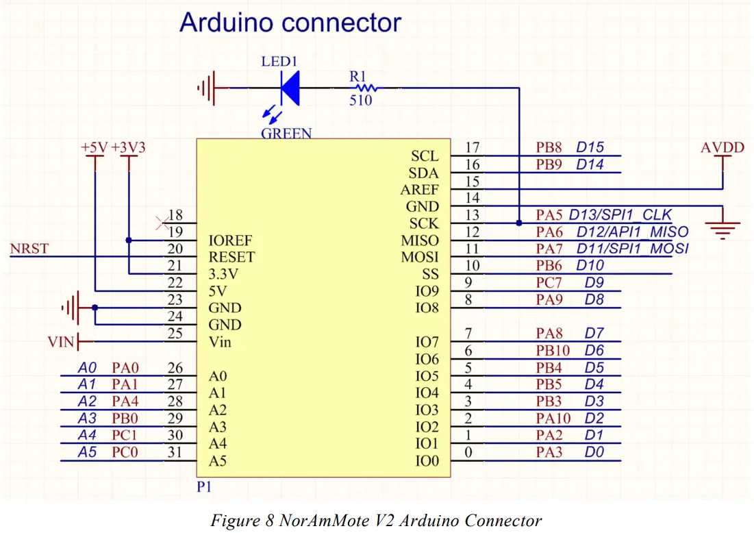
- An Arduino compatible interface is provided which enables the user to incorporate any of the widely available shields into their application.
- The SX1272LM1CEP NAMote-72 requires only a PC with a USB interface for programming and a USB compatible charger to recharge the internal battery.
Getting Started
Evaluation Kit Contents
The SX1272LM1CEP evaluation kit consists of:
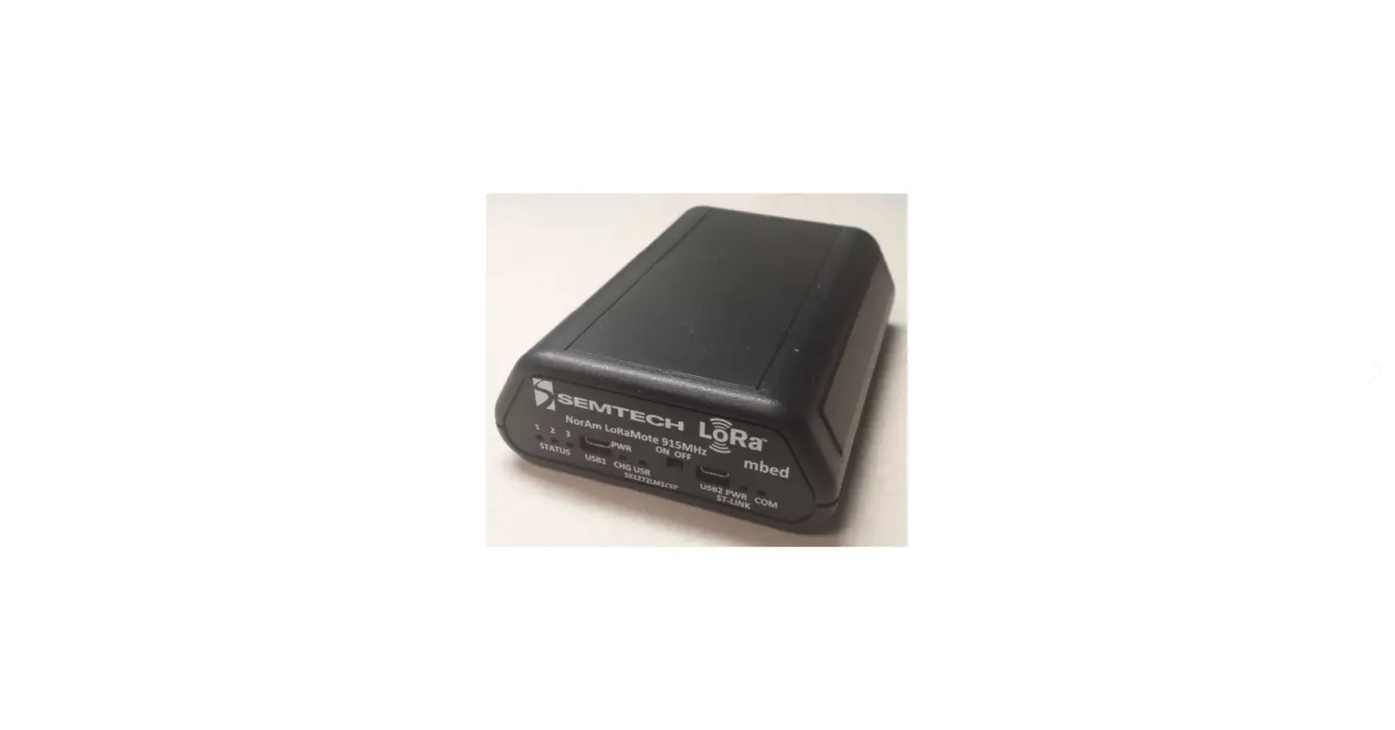
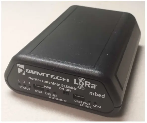
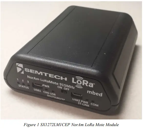
- SX1272LM1CEP – NAMote-72 NorAm LoRa Mote Device (shown below in Figure 1)
- USB type-A to USB micro-B cable

Ordering Information
| Part # | Description |
| SX1272LM1CEP | NAMote-72 – 915MHz North America LoRa Mote w/o SMA |
Connecting to the NorAm LoRa Mote (NAMote-72)
User Interface
The SX1272LM1CEP NorAm LoRa Mote is intended to enable a quick and easy range test of the SX1272 modules. Figure 2 below shows the Lora Mote endplate.
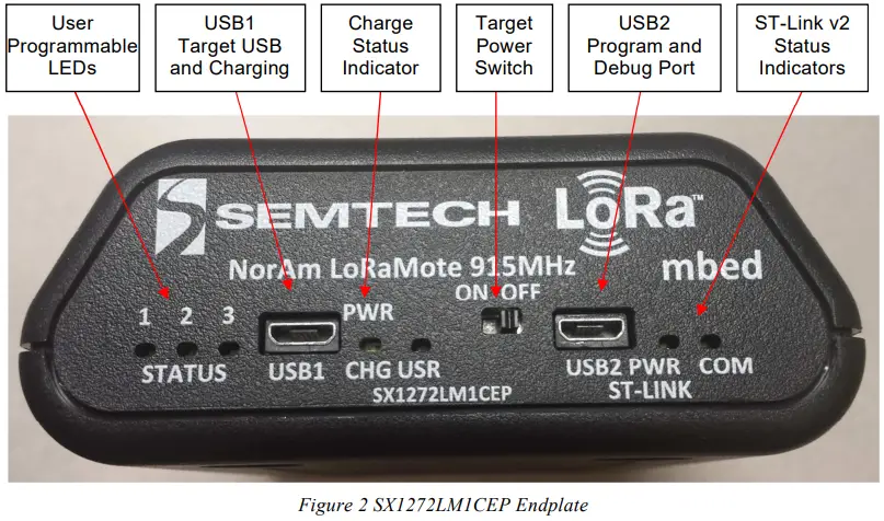
- USB1 Charge Port
The USB1 Charger port connects to an external USB wall charger or host computer USB port. Under low battery conditions, the charger can supply up to 700mA to recharge the battery while also powering the module. This charge status indicator LED will illuminate orange when the battery is charging and green when fully charged. - User Configurable LEDs
There are four LEDs provided, which under user control can be used to provide module status. The MCU ports for these LEDs are shown in the appendix. LED1 is red, LED2 is yellow, LED 3 is green and LED USR is red. Additional details can be found in the Appendix. - Power Switch
This switches on the battery to power the module. When this switch is in the OFF position, and a charger is connected to USB1, all charge current is directed to the battery. When a charger is connected and the switch is on, a portion of the charge current charges the battery and a portion helps power the module. - USB2 Program and Debug port
This port serves two functions. When connected to the Host PC through the USB cable, a mbed mass storage device will appear on the Host PC, permitting the user to program the module. In addition, a virtual com port will also appear, enabling serial communication with user firmware. The ST-Link status indicators show programming status. Green indicates successful download.
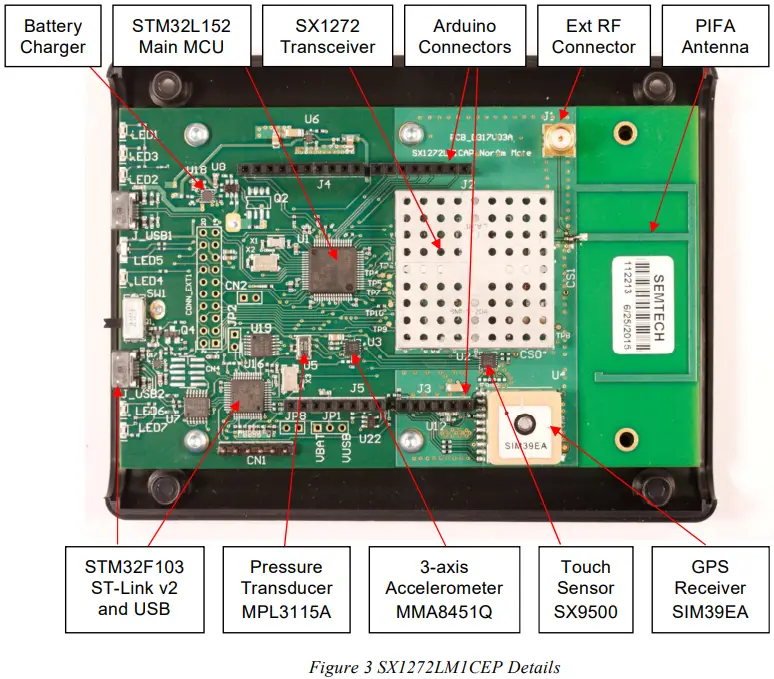
SX1272LM1CEP Device Hardware
The SX1272LM1CEP major component location is shown in
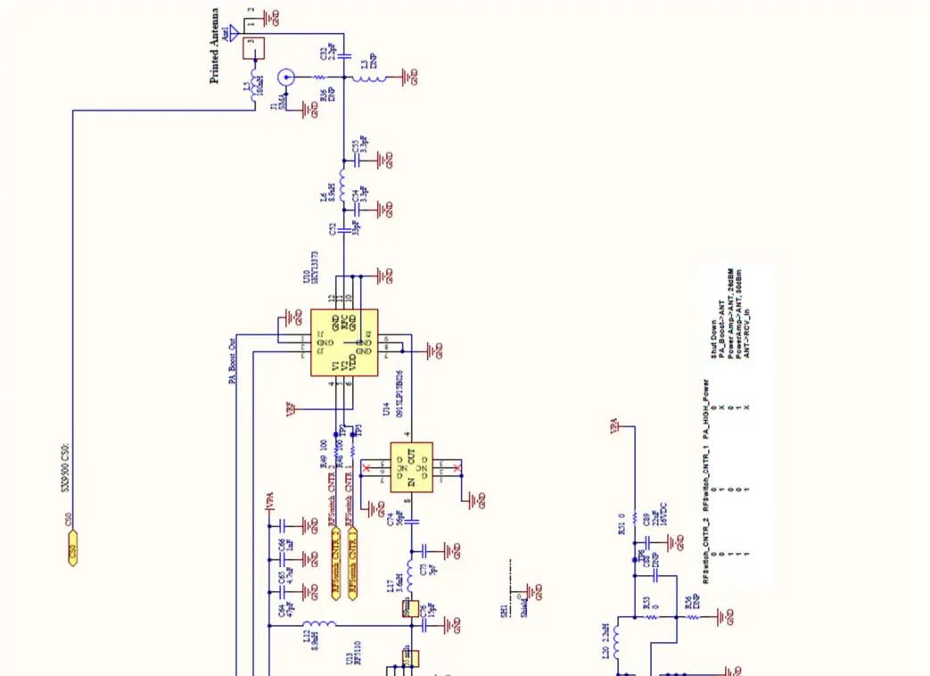
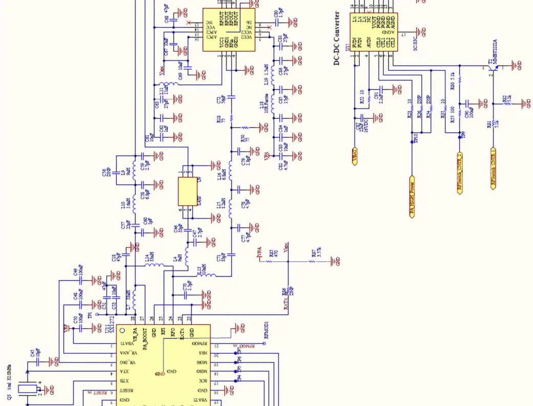
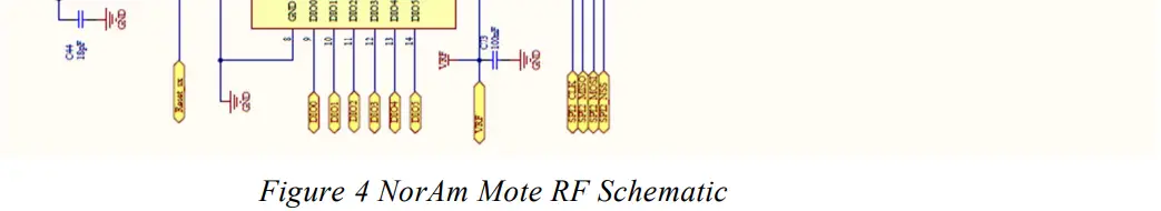
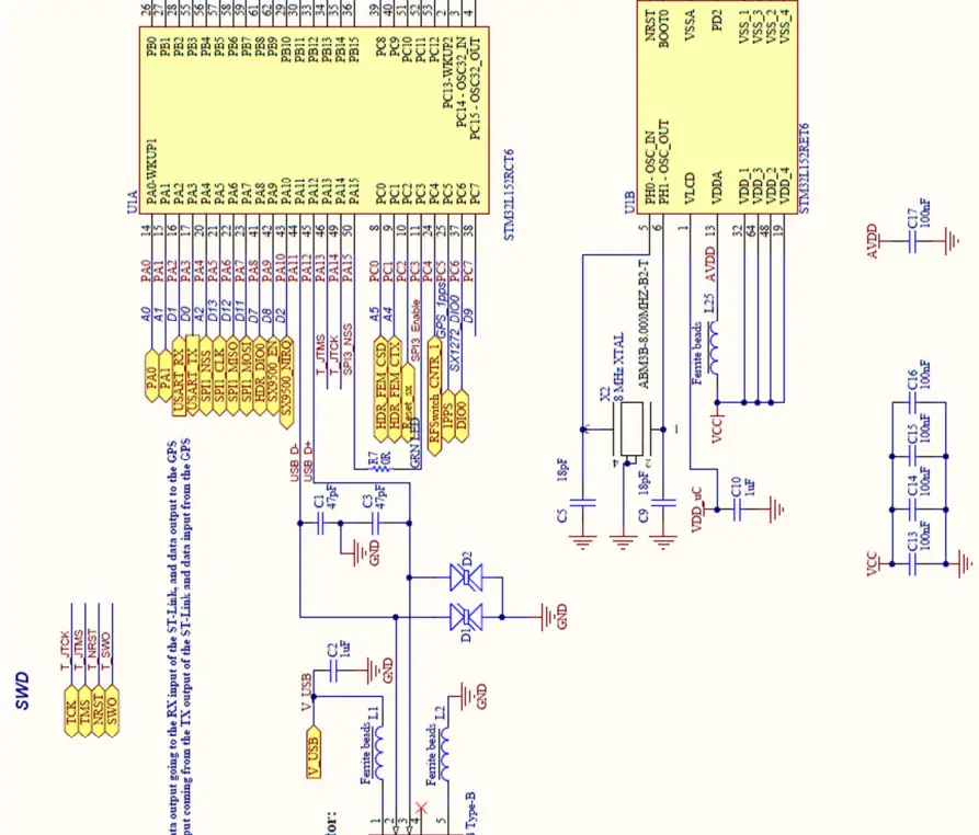
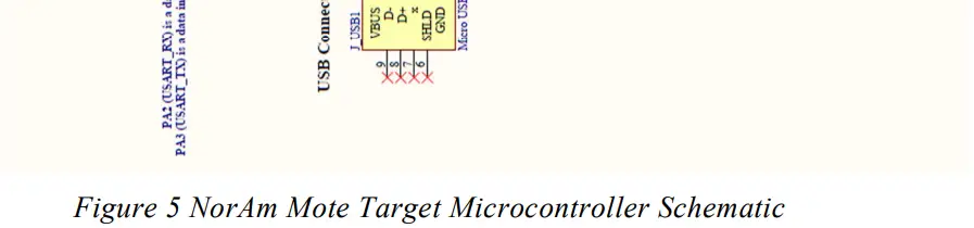
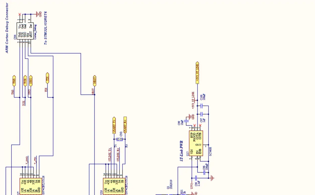
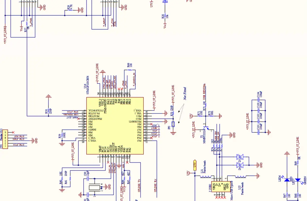
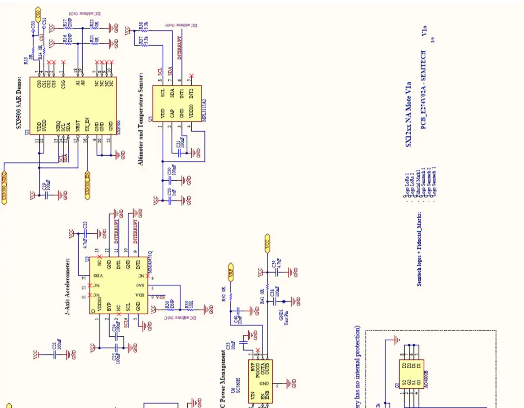
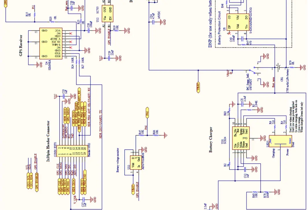
Figure 3 SX1272LM1CEP Details. The schematics are shown in Figure 4 NorAm Mote RF Schematic to Figure 7 NorAm Mote Peripherals Schematic
- NorAm Mote RF


- NorAm Mote RF


- NorAm Mote ST-Link


- NorAm Mote Peripherals


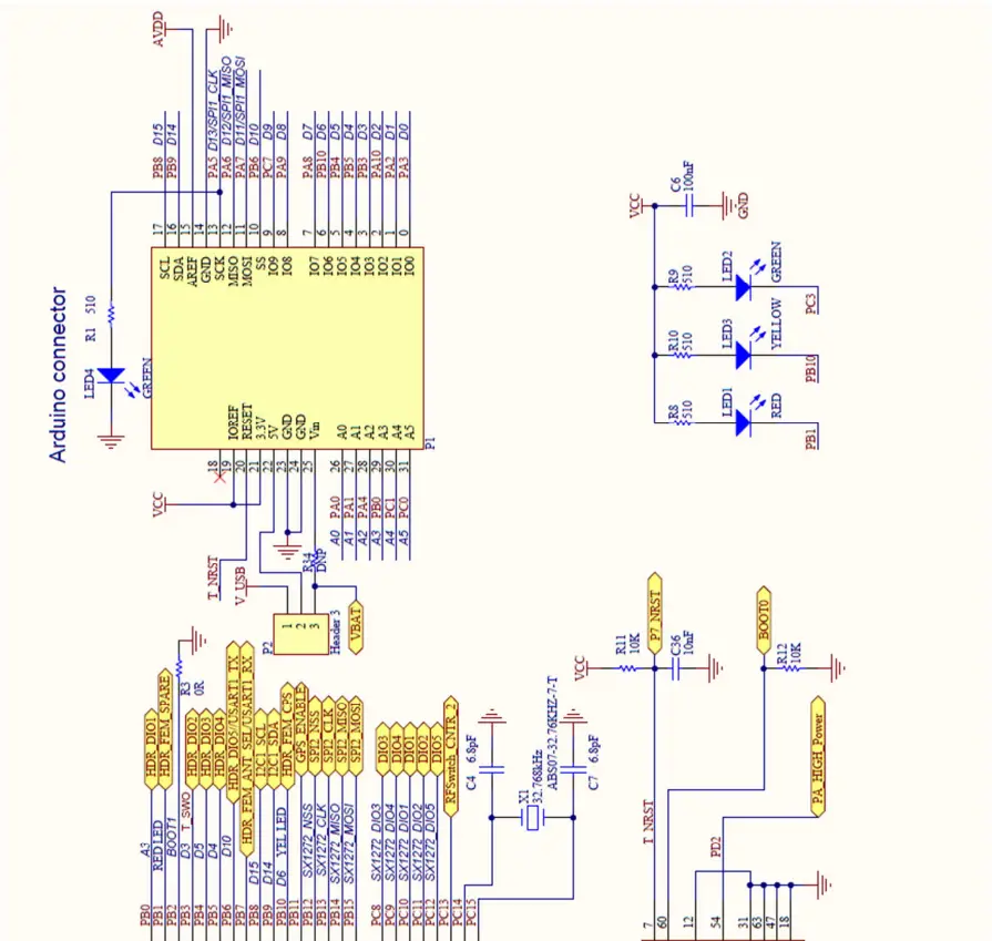


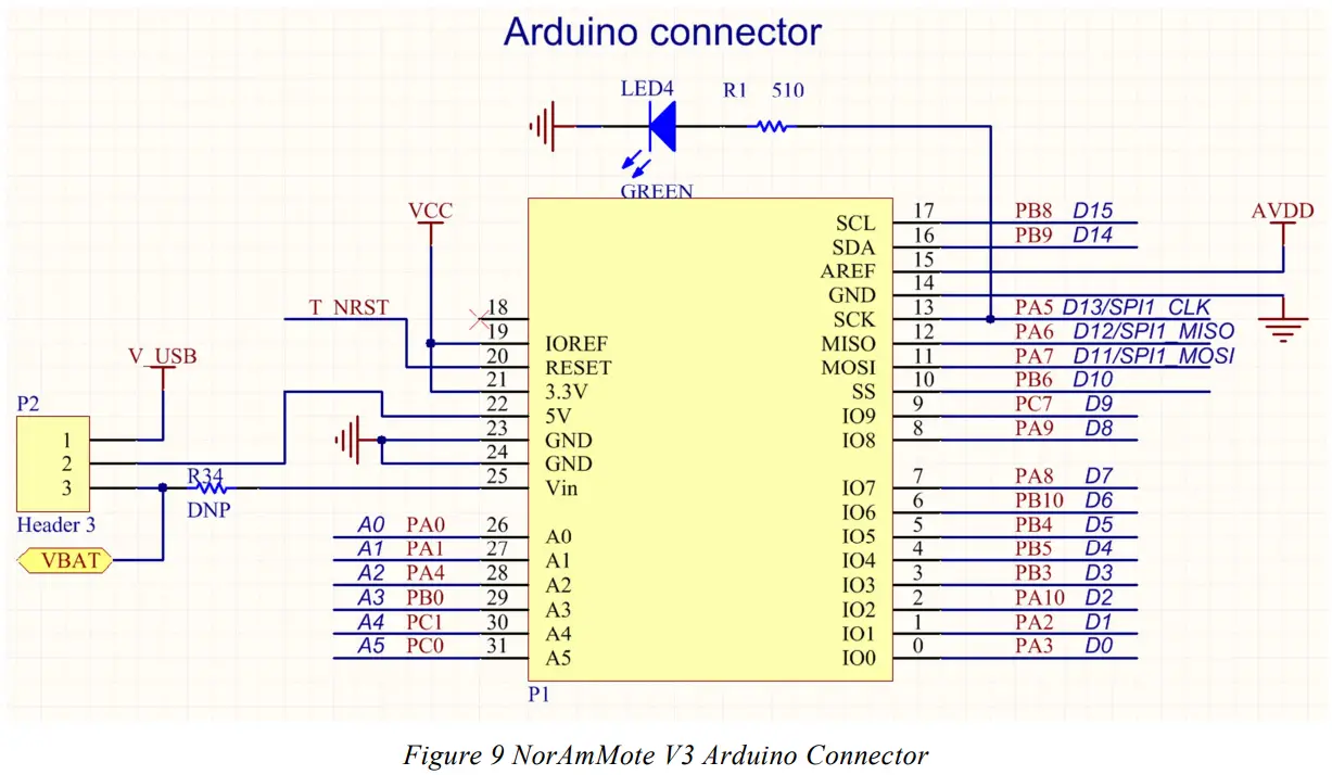
Arduino Connector
Using mbed to program the NorAm Mote
With mbed capability, there is no need to install firmware development tools or purchase a programmer.
Connecting to PC
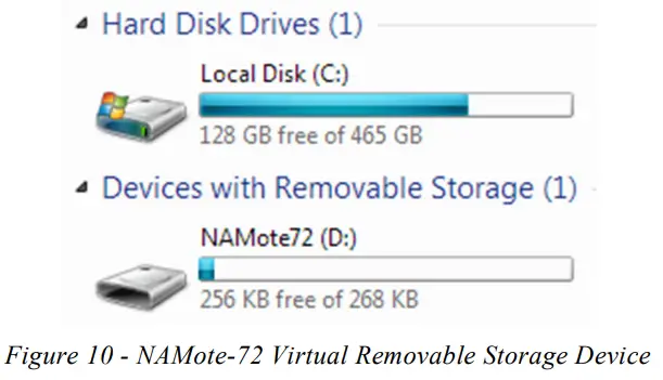
Before connecting the NorAm Mote to the Host PC, turn the power switch on. Then connect USB2, the ST-Link interface connector, to the PC. A new Removable Storage device, NAMote-72, will appear (see Figure 10 – NAMote-72 Virtual Removable Storage Device).
Creating the program on mbed
For detailed mbed program development instructions, go to the mbed website: http://mbed.org/
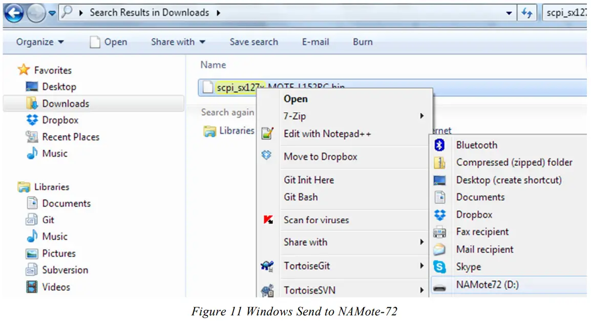
Once the program has been compiled, a binary file will be created and placed in your download directory. You can then copy and paste the file to the NAMote-72 storage device or use the Send command to directly load the file.
Note: The selected platform for the NorAm Mote on mbed IDE is NAMote-72 at: http://developer.mbed.org/platforms/NAMote-72/
Reference code examples
- NorAm Mote Test program
This program implements a SCPI command parser. When connected via the debug port, you can command the radio and peripherals to perform specific tasks or to set specific parameters. The serial port defaults to 9600bps N-8-1. This project includes libraries for interfacing with the peripherals. https://developer.mbed.org/teams/Semtech/code/scpi_sx127x/ - LoraWAN Location Monitoring
LMIC transmit example for NAmote-72 with GPS. https://developer.mbed.org/teams/Semtech/code/lmic_NAmote_GPS/
Appendix
MCU Port Assignments
| NA MOTE (MBED) | |||
| PORT | STM32L152C | PORT | STM32L152C |
| PA0 | Arduino_A0, BATT_Sense | PB9 | Arduino_D14/I2C1-SDA |
| PA1 | Arduino_A1 | PB10 | Arduino_D6/YELLOW LED, HDR_FEM_CPS (Header) |
| PA2 | Arduino_D1/USART_RX/to GPS Data Input | PB11 | GPS_ENABLE, battery voltage monitor (activehigh) |
| PA3 | Arduino_D0/USART_TX/from GPS Data Output | PB12 | SPI2_NSS->SPI_NSS (on board SX1272) |
| PA4 | Arduino_A2/SPI1_NSS, SX12xx NSS (Header) | PB13 | SPI2_CLK->SPI_CLK (on board SX1272) |
| PA5 | Arduino_D13/SPI1_CLK, SX12xx SCK (Header) | PB14 | SPI2_MISO->SPI_MISO (on board SX1272) |
| PA6 | Arduino_D12/SPI1_MISO, SX12xx SCK (Header) | PB15 | SPI2_MOSI->SPI_MOSI (on board SX1272) |
| PA7 | Arduino_D11/SPI1_MOSI, SX12xx SCK (Header) | PC0 | Arduino_A5, HDR_ FEM_CSD (Header) |
| PA8 | Arduino_D7, SX12xx DIO0(Header) | PC1 | Arduino_A4, HDR_FEM_CTX (Header) |
| PA9 | Arduino_D8/SX9500_EN | PC2 | Reset_sx (on board SX1272) |
| PA10 | Arduino_D2/SX9500_NIRQ | PC3 | GREEN LED, SPI3_Enable (WISUN) |
| PA11 | USART1_CTS->USB_D- | PC4 | RFSwitch_CNTR_1 |
| PA12 | USART1_RTS->USB_D+ | PC5 | from 1pps GPS out |
| PA13 | T_JTMS | PC6 | DIO0 (on board SX1272) |
| PA14 | T_JTCK | PC7 | Arduino_D9 |
| PA15 | SPI3_NSS | PC8 | DIO3 (SX1272_DIO3 on board SX1272) |
| PB0 | Arduino_A3, HDR_DIO1 (Header) | PC9 | DIO4 (SX1272_DIO4 on board SX1272) |
| PB1 | RED LED , HDR_ FEM_SPARE (Header) | PC10 | DIO1 (SX1272 DIO1 on board SX1272) |
| PB2 | BOOT1 (GND) | PC11 | DIO2 (SX1272 DIO2 on board SX1272) |
| PB3 | Arduino_D3, HDR_DIO2 (Header) | PC12 | DIO5 (SX1272 DIO5 on board SX1272) |
| PB4 | Arduino_D5, HDR_DIO3 (Header) | PC13 | WKUP2/RFSwitch_CNTR_2 |
| PB5 | Arduino_D4, HDR_DIO4 (Header) | PC14 | OSC32_IN |
| PB6 | Arduino_D10, HDR_DIO5 (Header)/USART1_TX | PC15 | OSC32_OUT |
| PB7 | HDR_FEM_ANT_SEL(Header)/USART1_RX | PD2 | PA_HIGH_Power |
| PB8 | Arduino_D15/I2C1_SCL | BOOT | 10k to GND |
LED Settings
| LED | On State | Off State |
| Status 1, Red | PB1 = 0 | PB1 = 1 |
| Status 2, Yellow | PB10 = 0 | PB10 = 1 |
| Status 3, Green | PC3 = 0 | PC3 = 1 |
| USR, Green | PA5 = 1 | PA5 = 0 |
GPS/battery voltage monitor Settings
| LED | On State | Off State |
| GPS/Batt Mon Enable, | PB11 = 1 | PB11 = 0 |
TR Switch/PA Power Settings
| RFSwitch_CNTR_2 | RFSwitch_CNTR_1 | PA_HIGH_Power | Operating Mode |
| 0 | 0 | 0 | Shut Down |
| 0 | 1 | 0 | PA_Boost to ANT |
| 1 | 0 | 0 | Power Amp to ANT Low |
| 1 | 0 | 1 | Power Amp to ANT High |
| 1 | 1 | 0 | ANT to RCV_in |
Output Power Level Settings +/- 1dB
| RegPaConfig 3-0 | Output Power, PA_HIGH_Power = 0 | Output Power, PA_HIGH_Power = 1 |
| 0 | 17.00dBm* | 24.50dBm |
| 1 | 18.00dBm* | 25.75dBm |
| 2 | 21.40dBm | 26.90dBm |
| 3 | 23.30dBm | 28.00dBm |
| 4 | 24.75dBm | 28.60dBm |
| 5 | 25.80dBm | 29.40dBm |
| 6 | 26.80dBm | 30.00dBm |
| 7 | 27.75dBm | 30.70dBm |
| 8 | 28.00dBm | 30.90dBm |
| 9 | 29.00dBm | 31.60dBm |
| 10 | 29.42dBm | 32.00dBm |
| 11 | 29.90dBm | 32.50dBm |
| 12 | 30.15dBm | 32.75dBm |
| 13 | 30.20dBm | 32.78dBm |
| 14 | 30.25dBm | 32.80dBm |
| 15 | 30.30dBm | 33.00dBm |
Use PA_Boost for power 18dBm or lower.
ABOUT COMPANY
- Semtech 2015
- All rights reserved. Reproduction in whole or in part is prohibited without the prior written consent of the copyright owner. The information presented in this document does not form part of any quotation or contract, is believed to be accurate and reliable and may be changed without notice. No liability will be accepted by the publisher for any consequence of its use. Publication thereof does not convey nor imply any license under patent or other industrial or intellectual property rights. Semtech assumes no responsibility or liability whatsoever for any failure or unexpected operation resulting from misuse, neglect improper installation, repair or improper handling or unusual physical or electrical stress including, but not limited to, exposure to parameters beyond the specified maximum ratings or operation outside the specified range.
- SEMTECH PRODUCTS ARE NOT DESIGNED, INTENDED, AUTHORIZED OR WARRANTED TO BE SUITABLE FOR USE IN LIFE-SUPPORT APPLICATIONS, DEVICES OR SYSTEMS OR OTHER CRITICAL APPLICATIONS. INCLUSION OF SEMTECH PRODUCTS IN SUCH APPLICATIONS IS UNDERSTOOD TO BE UNDERTAKEN SOLELY AT THE CUSTOMER’S OWN RISK. Should a customer purchase or use Semtech products for any such unauthorized application, the customer shall indemnify and hold Semtech and its officers, employees, subsidiaries, affiliates, and distributors harmless against all claims, costs damages and attorney fees which could arise.
Contact Information
- Semtech Corporation
- Wireless & Sensing Products Division
- 200 Flynn Road, Camarillo, CA 93012
- Phone: (805) 498-2111 Fax: (805) 498-3804
- E-mail: [email protected]
- [email protected]
- Internet: http://www.semtech.com


