PIMA DCM Wireless Magnetic Contact and Transmitter Instructions

Installation Instructions
English
![]()
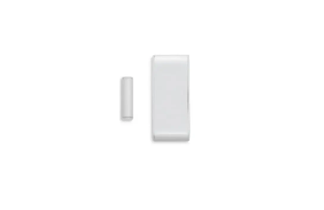
| 1 | Magnet |
| 2 | DCM Detector |
| 3 | LED |
| 4 | DIP Switch1 |
| 5 | Tamper |
| 6 | External Input |
| 7 | Batteries |
| 8 | Mounting Holes (Back Side) |
| 9 | Wiring Inlet |
| 10 | Magnet Location Notch |
| 1 | Magneto |
| 2 | Detector DCM |
| 3 | LED |
| 4 | Interruptor DIP3 |
| 5 | Interruptor contra sabotaje (Tamper) |
| 6 | Contacto para entrada externa |
| 7 | Baterías |
| 8 | Orificios de montaje (parte posterior) |
| 9 | Orificio para cableado |
| 10 | Marca para ubicación correcta del magneto |
DCM Wireless Magnetic Contact and Transmitter
The DCM is a FastLink technology wireless magnetic contact and universal transmitter with external hardwired input, designed for the
FORCE Series and VISION intruder alarm systems. Using the DCM in FORCE requires the installation of a wireless receiver.
The DCM has a modern design and is battery operated. It is mounted on doors and windows, and wirelessly transmits an event to the control panel when they are opened. The DCM’s universal transmitter, combined with the external hardwired input, can be used to transmit events from normally close contact devices, such as wired PIR detectors. The devices connect to the DCM’s terminal block and are reported to the control panel as a separate zone. The magnetic contact can be bypassed, so the DCM will only be used as a universal transmitter.
The DCM alerts on low battery, and has a tamper switch that alerts when its enclosure is opened or removed from the wall. It transmits a test event every 15 min. Its LED indicates on any alarm transmission, and when the battery is low.
![]() Cautions: the DCM is based on wireless (RF) transmissions. Any wireless transmission can be subject to RF interference and, although unlikely, this interference may cause the DCM to not
Cautions: the DCM is based on wireless (RF) transmissions. Any wireless transmission can be subject to RF interference and, although unlikely, this interference may cause the DCM to not
operate as intended. RF transmissions will be attenuated by tinted glass, in wall isolation with metal foils, metal objects, etc.
Technical specifications
| Frequency (MHz) | Models | |
| One-Way | Two-Way | |
| 433.92 | DCM143 | DCM243 |
| 868.95 | DCM187 | DCM287 |
- Battery: 2X 1.5V, AAA, Alkaline
- Sizes: 8.5 X 3.5 X 1.4 cm, Magnet: 4 X 1 X 1.5 cm
- Weight: 60gr
- CE Compliance
- Battery Life Cycle: Up to 5 Years (Normal Usage)
- Operating Temperature: -10 to +50 °C
- Humidity (Max.): 93% R.H., Non-condensing
- DCM143/187 only
- Только в DCM143/187
- Solo en modelos DCM143/187
Content of the product package
- DCM magnetic contact + magnet
- Two batteries
- Screws, mounting tapes
- This guide
How to replace the batteries
- Insert a slotted screwdriver to the slot at the bottom of the device and open the enclosure.
- Take out the batteries and place new ones in the holder. Observe polarity! The detector goes into test mode for five minutes, before going to normal mode.
- Close the enclosure and test the DCM; see How to test the DCM below.

How to install the DCM
You can mount fix the detector and magnet using the supplied screws or tapes. In any way, it is recommended to attach the detector to the fixed frame, and the magnet to the movable part (door or window).
To mount the detector using screws, do the following.
- Insert a slotted screwdriver to the slot at the bottom of the detector and open the enclosure.
- Remove the knock outs on the back of the enclosure (no. 8 in the figure on the first page).
- Fix the back to the surface with screws. Make sure the magnet is centered with the notch on the enclosure’s side, and is no more than two centimeters away from the enclosure.

Make sure to use the tamper’s hole (the middle one), to alert when the DCM is being removed from the mounting surface.
When using the tapes to mount the DCM, the tamper will only alert when the enclosure is opened. - If you use an external device, connect it to the terminal block (no. 6 in the figure on the top page) using two wires (not supplied).
- Close the enclosure, running the external device’s wires through the inlet (no. 9 in the figure on the first page).
- Fix the magnet’s (no. 1 in the figure on the first page) backplate to the surface with screws. The magnet should be located against the mark on the detector (no. 10 in the figure on the first page), two centimeters away from the detector.
- Insert the magnet to the enclosure and close it.
- Enroll the DCM; see the alarm system’s Installation guide for instructions.
- Test the DCM, using the Tests and Diagnostics menu.
How to set the DIP switch5
The DIP switch has two switches, for setting the magnet/transmitter and LED modes of the DCM, as described below..
| Switch | ON | OFF |
| 1 – Magnet/Transmitter and external hardwired input | The magnet and the transmitter are connected | Only the transmitter is connected |
| 2 – LED | The LEDs are switched on; see more below. | The LEDs are switched off |
LEDs
| Color and state | Description | Color and state | Description | ||||
| 1 blink | Battery OK, tamper closed | 1 blink | Battery OK, tamper open | ||||
| Green | 2 blinks* | Reception level: good | Red | 2 blinks | Low battery | ||
| 3 blinks* | Reception level: excellent | 3 blinks* | Reception level: poor | * Two-way only | |||
How to enroll the DCM
On the Wireless Peripherals menu you can enter the DCM’s serial number (printed on its label) manually, or enroll it automatically: select
Enrollment-Any Event, and while in automatic enrollment mode, open/close the magnet.
How to test the DCM
When placing new batteries the detector goes into test mode for five minutes. During this time the LED will flash according to the LED table above, even if the DIP switch is in off position. The tamper switch will not report during the first three minutes.
Universal transmitter
The universal transmitter, combined with the external hardwired input, can be used to transmit events from normally closed contact devices – pushbuttons, hardwired detectors, and door contacts – to the control panel. The devices connect to the terminal block of the DCM (no. 6 in the above figure) using two wires (not supplied). To disconnect the magnet and use only the transmitter, set DIP switch #1 to the OFF position.
Ordering information
| One-way | Two-way | ||
| · DCM143: P/N 8831002 | · DCM187: P/N 8831028 | · DCM243: P/N 8831202 | · DCM287: P/N 8831228 |
5 DCM143/187 only


