
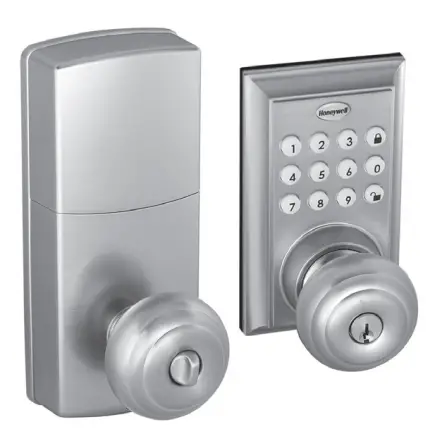
 Honeywell 8812309S Safes & Door Locks
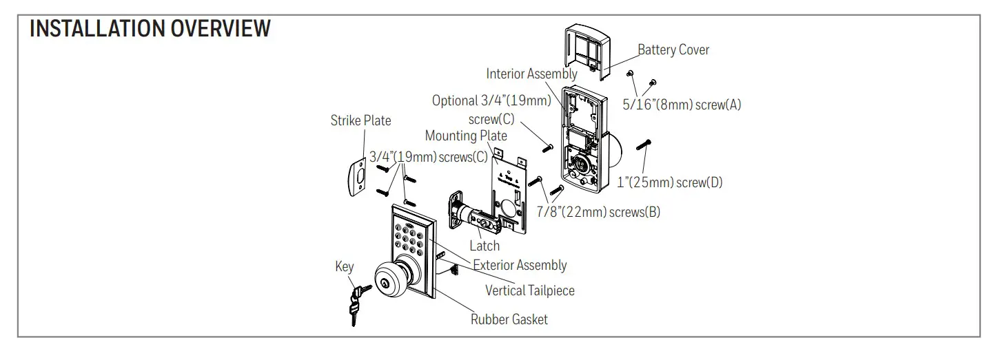
Package Includes
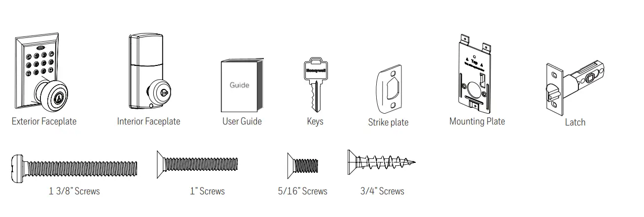
- 1 – Exterior Faceplate
- 1 – Interior Faceplate
- 1 – User Guide
- 2 – Keys
- 1 – Strike Plate
- 1 – Mounting Plate
- 1 – Latch
- 1 – 1 3/8” Screws
- 2 – 5/16” Screws
- 2 – 1 “ Screws
- 5 – 3/4” Screws
Please carefully check the above list to confirm all items have been received. If any items are missing, please contact Consumer Assistance. ( See page for contact information)
Read this manual carefully before installing and operating!
PACKAGE CONTENTS
TOOLS REQUIRED
Tools Required for Installation on Pre-drilled Doors:
- Phillips Screwdriver
NOTE: DO NOT USE a drill.
Batteries (not included)
Electronic lock requires (4) High-Quality AA Alkaline batteries. When all 4 batteries are installed in the correct position, hear 2 beeps and the keypad will illuminate blue. DO NOT TOUCH the keypad until the keypad stops illuminating.
Tools Required for Installation on Doors That Require Drilling:
- Drill
- Tape Measure
- pencil
- 2-1/8” (54mm) Drill Hole Saw
- 1” (25mm) Drill
- 1/16” (2mm) Drill
- Chisel
- Hammer
- Phillips Screwdriver
PAY CLOSE ATTENTION TO ALERTS
DO NOT RETURN TO THE STORE! If any parts are missing or damaged, please call Customer Service toll free at 1-800-860+1677 Ext. 1801 (M-F 8am – 5pm PST)
PREPARE DOOR AND JAMB
NOTE: For installation on doors with pre-drilled holes skip to page 4.
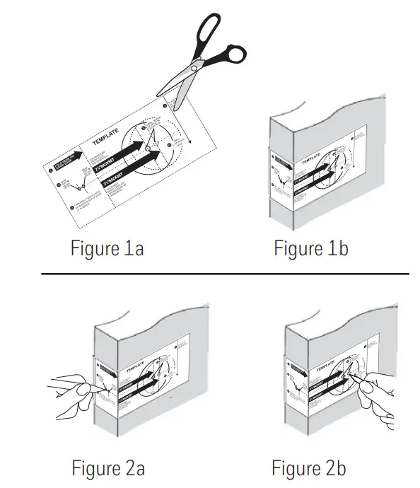
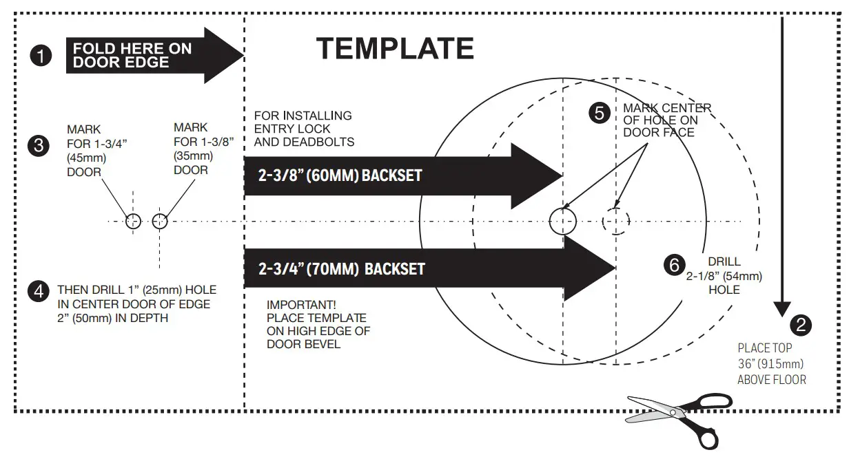
- TEMPLATE
- Cut out template printed on page 20 of this Manual (Figure 1a).
- Fold the template and place it on door 36” (915mm) from the ground as marked (Figure 1b).

- MARK THE DOOR FOR DRILLING
- Mark the center hole on the door edge through the guide on the template for 1” (25mm) latch bolt (Figure 2a).
- Mark the center hole on the door face through the guide on the template for 2-3/8” (60mm) or 2-3/4” (70mm) backset (Figure 2b).
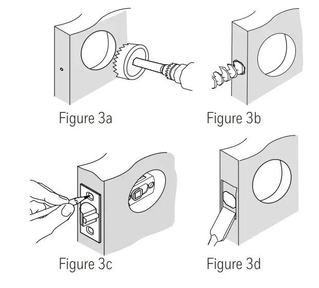
- DRILL AND CHISEL DOOR
- Drill 2-1/8” (54mm) hole through the door face as marked for lock set (Figure 3a).
- Drill 1” (25mm) hole in the center of the door edge for Latch Assembly (Figure 3b).
- Insert Latch Assembly in the hole keeping it parallel to face of the door. Mark the outline and remove the latch(Figure 3c).
- Chisel 1/8” (3mm) deep or until the latch face is flush with do or edge (Figure 3d).

NOTE: For Drive in Latch, drill the hole size indicated on the template and press until it is flush with door edge.
- MARK AND DRILL DOOR JAMB
- Mark the center hole on edge of the jamb even with the center of the Latch Bolt on the door edge. (Figure 4a).
- Drill 1” (25mm) hole 1-3/16” (30mm) deep in the door jamb on center mark (Figure 4b).
- Outline the outside edges of the Strike Plate (Figure 4c).
- Chisel 1/8” (3mm) deep for Strike Plate or until flush (Figure 4d).
- Install Strike Plate using two 3/4” (19mm) screws provided (Figure 4e).

ADJUSTING AND INSTALLING LATCH
NOTE: Latch is shipped with the backset set at 2-3/8” (60mm) Measure the backset (backset is distance between edge of the door and the center of Lock).
TO CONVERT FROM 2-3/8” (60mm) BACKSET TO 2-3/4” (70mm) BACKSET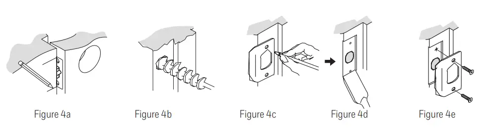
TO CONVERT FROM 2-3/4” (70mm) BACKSET TO 2-3/8” (60mm) BACKSET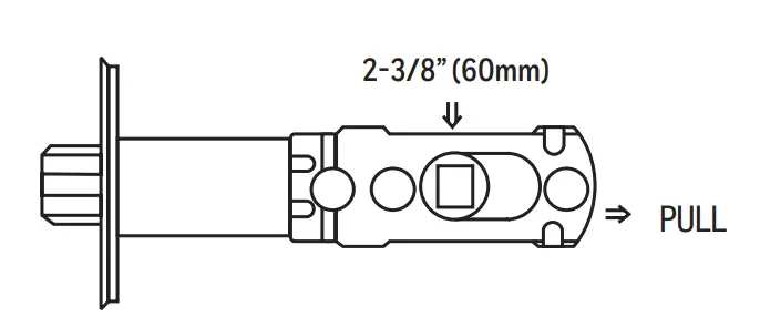
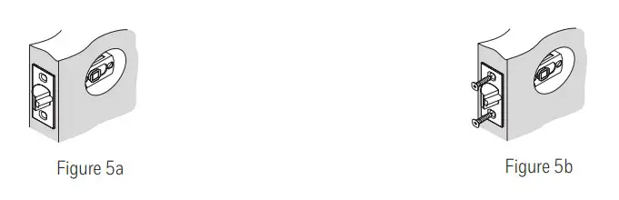
NOTE: Curved part of Latch always faces the curved portion of Strike Plate.
INSTALLING THE LATCH (need Phillips head screwdriver)
- Make sure the face plate sits flush with the door. Do not force the latch into the mortise flush. Chisel out excess material if necessary for a flush fit (Figure 5a).
- Using two 3/4” (19mm). screws provided, screw the latch into the door with a handheld screwdriver. DO NOT OVER-TIGHTEN (Figure 5b).

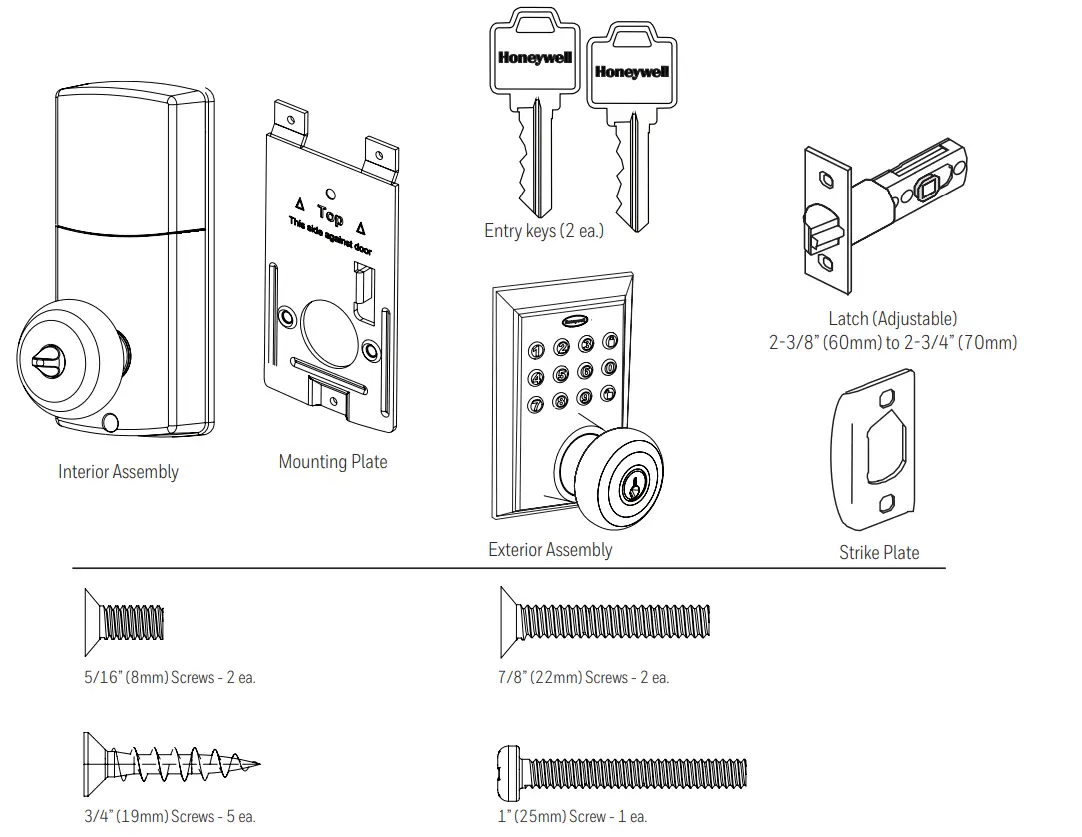
INSTALLING EXTERIOR ASSEMBLY
INSTALLING THE EXTERIOR ASSEMBLY
Work with the Door Open for easy access. To access the mounting plate, unpack the Interior Assembly and remove the battery cover by sliding the cover upward. Locate the screws holding the Mounting Plate to the Interior Assembly. Remove the screws to release the Mounting Plate from the Interior Assembly.
- Unpack the Exterior Assembly. Use care to not scratch the green circuit board during handling and installation.
- Check that the Rubber Gasket is properly seated on the Exterior Assembly (Figure 6a-b).
- Insert the Exterior Assembly onto the door with the tailpiece going through the Latch spindle in the VERTICAL POSITION. Route the Control Wire through the door over the Latch (Figure 6c).


SECURING THE EXTERIOR ASSEMBLY TO THE DOOR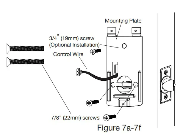
- From the side marked “This side against the door”, route the Control Wire through the rectangular slot in the Mounting Plate (Figure 7a).
- Place Mounting Plate against the door with the tailpiece passing through the center hole in the three-hole set (Figure 7b).
- Secure the Mounting Plate to the Exterior Assembly using two 7/8” (22mm) Screws (Figure 7c).
- Hand tightens with a Phillips Screwdriver leaving loosely connected (Figure 7d).
- Check that the Rubber Gasket is properly aligned and correct as necessary (Figure 7e).
- Check the vertical alignment of the lock (Figure 7f).
- Tighten securely with a hand-held Phillips Screwdriver. DO NOT OVER-TIGHTEN.
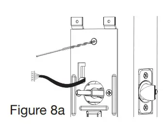
OPTIONAL INSTALLATION
- Using a 1/16” (2mm) drill bit, drill a pilot hole in your door using the Mounting Plate upper hole as a guide (Figure 8a).

- Insert one 3/4” (19mm) screw and tighten.
NOTE: Lock and unlock using the key to see if the Latch is opening and closing easily.
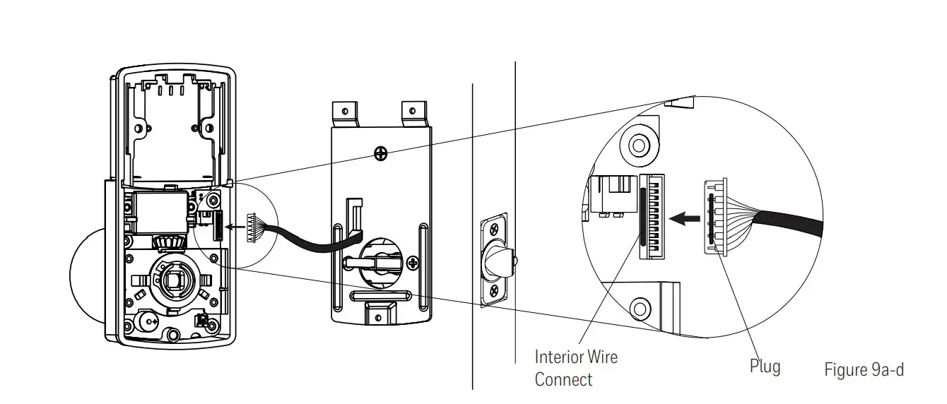
ATTACH THE CONTROL WIRE TO THE INTERIOR ASSEMBLY
- Use care to attach the Control Wire male plug to the Interior Assembly female socket connector (Figure 9a).
- Do not force the Control Wire male plug into the Interior Assembly female socket connector (Figure 9b).
- The Control Wire male plug has two alignment tabs on the smooth side of the plug which is the top of the plug (Figure 9c).
- The Control Wire male plug is inserted with the smooth side up into the Interior Assembly female socket connector (Figure 9d).

ATTACH THE INTERIOR ASSEMBLY TO THE DOOR
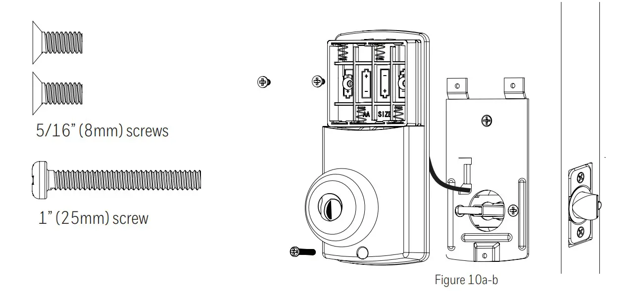
- Position the Interior Assembly over the tailpiece and push the Interior Assembly against the door (Figure 10a).
- Using two 5/16” (8mm) screws and one 1” (25mm) screw, attach the Interior Assembly to the Mounting Plate.
DO NOT OVER-TIGHTEN SCREWS (Figure 10b). NOTE: Lock and unlock using Interior Knob to see if the latch is opening and closing easily.
 NOTE: Lock and unlock using Interior Knob to see if the latch is opening and closing easily.
INSTALLING INTERIOR ASSEMBLY
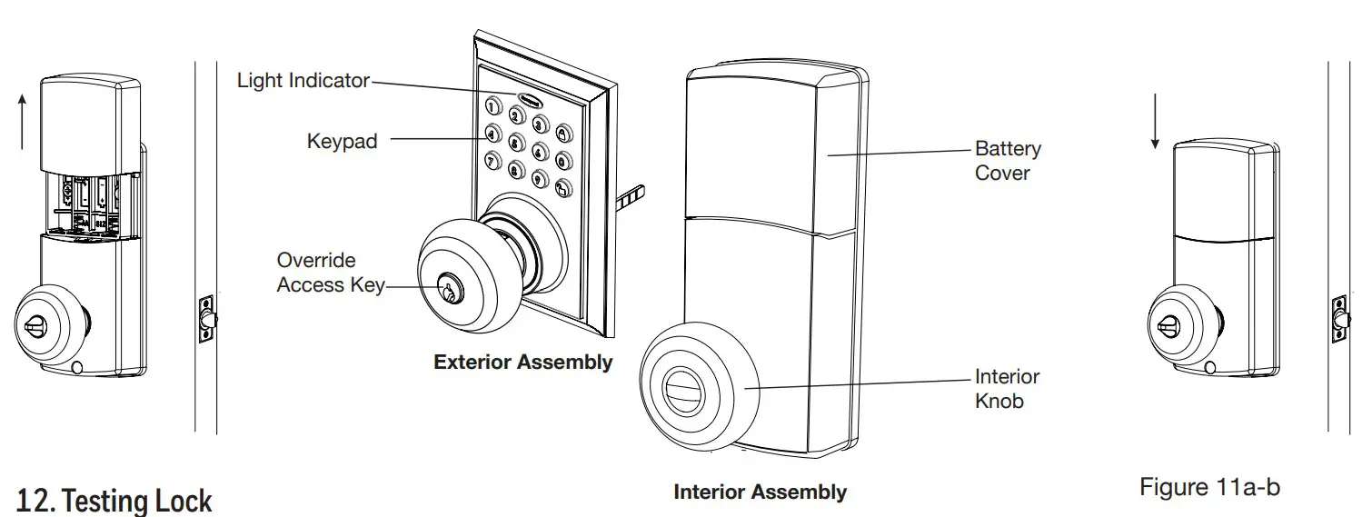
- Installing Batteries
- Insert 4 AA high-quality Alkaline batteries into the Battery Compartment in the direction noted +/- on the Compartment. The Lock will beep 2 times, the keypad will illuminate blue, and the Honeywell button will flash green twice to signify that it has received power (Figure 11a).
NOTE: Do not touch the Keypad until the blue light turns off.
Do not use rechargeable batteries or non-alkaline batteries. - Slide the Battery Cover down into the track on the Interior Assembly to cover the batteries (Figure 11b).

- Insert 4 AA high-quality Alkaline batteries into the Battery Compartment in the direction noted +/- on the Compartment. The Lock will beep 2 times, the keypad will illuminate blue, and the Honeywell button will flash green twice to signify that it has received power (Figure 11a).
- Testing Lock
With the Door Open- Test the Lock using the Interior Knob. The Latch should move smoothly.
- Test the lock using the Keypad. To lock press and then press “ 1234”
 to unlock.
 to unlock.
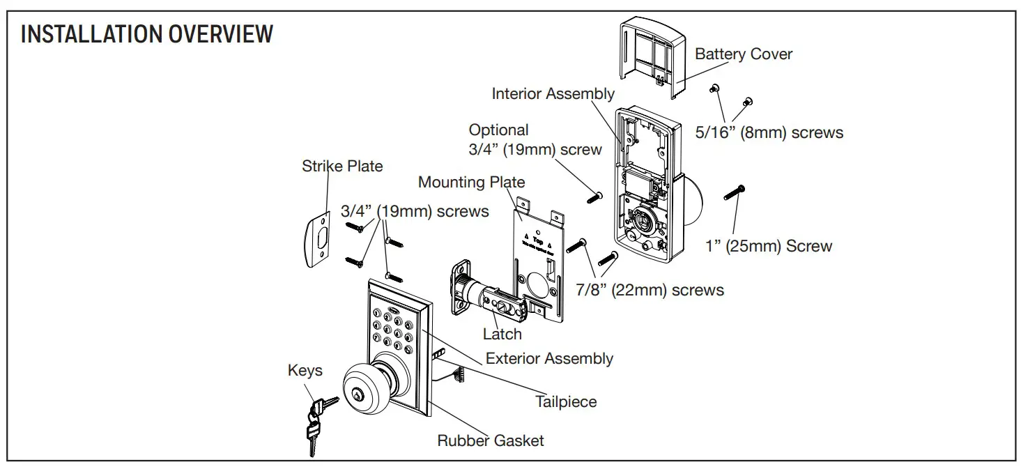
HONEYWELL LOCK MOBILE APPLICATION INSTALLATION & USE
PRIMARY APP ICONS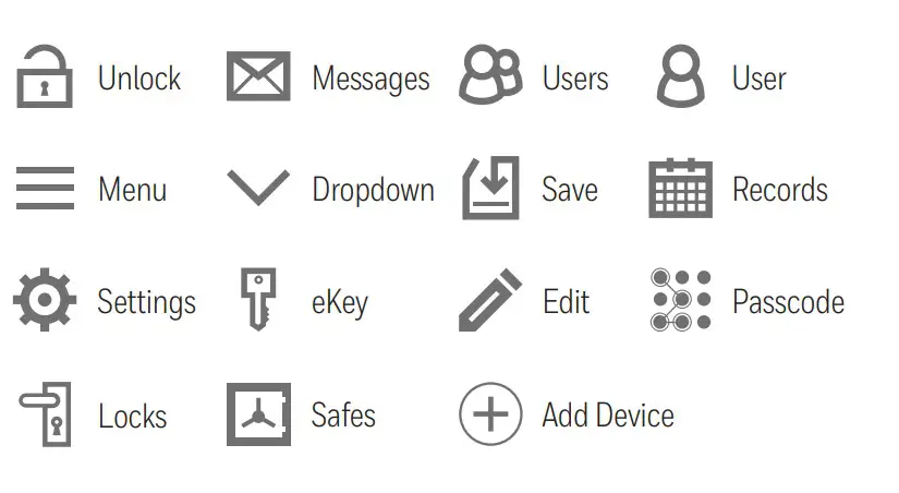
KEYPAD SYMBOLS
AP
- Administrator Passcode
NP - New Passcode
RP - Received Passcode
USER TYPES
- Administrative User – Able to send & delete eKeys & Passcodes, change AP, and remove connected lock(s)
- Authorized User – Able to send eKeys & Passcodes, can delete only the eKeys & Passcodes they send
- User – Able to use eKeys & Passcodes assigned from Administrative & Authorized Users.
VERY IMPORTANT
After connecting to a new lock as an A, the factory default Passcode will be deleted, and replaced with a new AP, which is randomly assigned, and should be changed in the lock’s settings immediately.
Once the door is unlocked with the App, you will have to manually lock it. (See page 11 to set the Auto Lock feature)
Before connecting to a lock please ensure that Bluetooth is enabled on your phone and you are standing in front of the lock, and it is activated.
Ensure that Push Notifications are enabled for the App.
See page 16 for information on features and settings for the App.
APPLICATION SETUP OPTIONS
After you have installed your Bluetooth Lock, download the free “Honeywell Lock” App on your smart phone using one of the following options:
- Search “Honeywell Lock” in the App Store or Google Play Store.
REGISTER APP AND CREATE ACCOUNT
- Open the App after it has been installed on your Smartphone.
- Select “Register New Account”
- Follow prompts on screen and enter Mobile Phone Number and Password
- Select “Get Code”
IMPORTANT: “Verification Code” sent as text message. “Code” must be entered within 60 seconds. If the wrong code or past 60 seconds, you must select “Get Verification Code” to resend a new code. - Input received verification code
- Select “Create Account”.
CONNECT TO BLUETOOTH LOCK
IMPORTANT: Your Bluetooth must be enabled and you must be within range of the lock.
- Press any key on Lock to activate the Lock. (Digital keys are lit when activated).
- Click the “+” icon on the start screen.
- Select which type of lock you would like to add
- Click on available lock
- Follow prompts to name the device
After you have connected the lock to the Bluetooth App, the Admin. Digital Passcode must be reprogrammed by going to the “Lock Setting” page.
MANAGE LOCK SETTINGS
Go to “Lock Settings” by selecting the “Settings icon “*” in the top right corner of the screen.
SET ADMIN PASSCODE
IMPORTANT: Your Bluetooth must be enabled and you must be within range of the lock.
- Select “Admin Passcode” from the list.
- You will be prompted to enter your Account Password.
- Enter a new 4 to 9-digit password of your choice and press “DONE”.
CHANGE LOCK NAME
- Select “Name” from the list
- Input the name you want to assign to this lock and press “DONE”.
ACTIVATE AUTO LOCK
- Select “Auto Lock” from the list
- Toggle Auto Lock On/Off
- Input the Set Time for Auto Lock
- Press “OK” to Save changes
NOTE: Auto lock can also be programmed using the digital keypad
ADD LOCK TO GROUP
If no groups exist you will have to create one. Press “Create Group” and enter the group name.
- Select “Group” from the list.
- To create a new group, press “Create Group” and enter the group name.
- Select the Group to place the lock in.
- The words “change successfully” will appear to confirm the action.
UPGRADE THE CONNECTED LOCK
In order to upgrade you have to be the AP for the lock, and within Bluetooth range
The App and the lock have been successfully connected when the green light on top of the lock turns on, indicating that the lock is upgrading.
- Press “Lock Upgrade” from the list to Check for Updates
- Press “Upgrade’ (in case a pop up notification appears, follow it to finish the upgrade).
USING APP TO LOCK AND UNLOCK
UNLOCK DOOR WITH THE APP
- Open App, choose Lock and Touch App to Unlock
- Open App & Touch 2 Keys to Unlock
LOCK DOOR WITH THE APP
- Open the App
- Click on the connected safe you wish to lock
- Press and hold the lock button until the safe has locked.
AUTO LOCK
If enabled in “Lock Settings”, it will automatically lock after 20 to 900 seconds.
USING A KEYPAD TO LOCK AND UNLOCK
UNLOCK DOOR WITH A KEYPAD
- Press any key on the Lock to activate the Lock. (Digital keys are lit when activated).
- Enter Passcode +
LOCK THE DOOR WITH THE KEYPAD
- The press lock button on the keypad.
TOUCH TO UNLOCK
IMPORTANT: Your Bluetooth must be enabled and you must be within range of the lock.
- “Touch to Unlock” must be on in “System Settings”.
- Press any key on Lock to activate the Lock. (Digital keys are lit when activated).
- Press any key to unlock.
SYSTEM SETTINGS
- Go to the Main menu by pressing the * icon at the top left corner of the screen.
- Select “System Settings”
- Select below settings as desired.
PATTERN PASSWORD
Create a pattern to unlock the App. Provides extra security
BEEP ON UNLOCKING
Mute or enable a sound when the door is unlocked
VIBRATION
Enable or disable the App’s vibration feature
TOUCH TO UNLOCK
Enable/disable the ability to touch the physical keypad to unlock the lock (see page 10 under “Using the App”)
MANAGE GROUPS
Assign locks to groups
WIFI GATEWAY
Connect and use the App in conjunction with an Internet Gateway
SECURITY SETTING –
Adjust the following settings
- RESET LOCK VERIFICATION –
Notifications when the lock is reset - SEND EKEY VERIFICATION –
Notification when an eKey is sent - SEND PASSCODE VERIFICATION –
Notification when a Passcode is sent - DELETE EKEY VERIFICATION –
Notification when an eKey is deleted - CHANGE MANAGEMENT PASSCODE VERIFICATION –
Notification when a Passcode is changed - AUTHORIZE VERIFICATION –
Notification when a U is authorized
ACCOUNT MANAGEMENT
- Go to the Main menu by pressing the * icon at the top left corner of the screen.
- Select “Account Management”
- Select the below settings as desired.
PROFILE PICTURE
- Click on the picture at the top of the page
- Change the picture associated with the account by clicking the icon
NICKNAME
- Click on “Nickname”.
- Enter a nickname for the account.
EMAIL/MOBILE NUMBER
- Click on “Email”
- Enter an email address to the account.
- Select “Get Code”
IMPORTANT: “Verification Code” sent as a text message. “Code” must be entered within 60 seconds. If the wrong code or past 60 seconds, you must select “Get Verification Code” to resend a new code. - Select “Admin Passcode” from the list.
RESET PASSWORD –
- Click on “Reset Password”
- Reset your current password with a new password
VIEW NOTIFICATIONS
- Open the App
- Select the icon at the top right of the Home screen
- Select the message you would like to read.
CREATE & SEND PASSCODES BY EMAIL OR TEXT MESSAGE
Passcodes can be sent via email or text to any SMS enabled mobile device.
SENDING PASSCODES
- elect the lock you want to send a Passcode for
- Select the in the bottom menu Permanent Passcodes –
- Select “Permanent” from the top tabs Timed Passcodes –
- Select “Timed” from the top tabs
- Input the time frame
Cyclic (Recurring) Passcodes - Select “Cyclic” from the top tabs
- Input the time frame
One-Time Passcodes - Select “One-Time” from the top tabs
- Press “Generate” to get a new Passcode
- Input the mobile number, or email address you would like to send the Passcode to
- Press “Send by email” or “Send by Msg.”
CREATE AND SEND EKEYS
To send an eKey, the receiver must have a Honeywell App account. The operation will fail if the Receiver is not registered, or the wrong information is input when sending an eKey.
SENDING KEYS
- Select the lock you want to send a Passcode for.
- Select the in the bottom menu.
NOTE: Auto lock can also be programmed using the digital keypad – see pagePermanent Passcodes –- Select “Permanent” from the top tabs
- Enter the receiver’s Account Name
Timed Passcodes – - Select “Timed” from the top tabs
- Input the time frame
- Enter the receiver’s Account Name
- Press send
- You will receive a notification once the key has been received.
MANAGE USERS
Ensure that WiFi is connected and working in order to manage Users associated with a connected lock
FREEZE A USERS’ EKEY
- Select the lock with the eKey you want to Freeze
- Select the
 in the bottom menu
 - Select the User you would like to Freeze
- Select “Freeze”
- Confirm that you would like to Freeze the User
 in the bottom menu
CHANGE A U TO AU
- Only A can authorize other Users. An AU can send eKeys and Passcodes to other Users.
- Select the lock with the eKey you want to authorize
- Select the in the bottom menu
- Select the top eKey tab
- Select the User you would like to authorize
- Select “Authorize”
- Input your account Password
- Once that User’s account has changed you will be notified
RENAME USERS
- Select the lock with the eKey you want to rename
- Select the in the bottom menu
- Select the top eKey tab
- Select the User you would like to Rename
- Select “Rename”
- Input the new name you would like to use
- Press


EDIT TIME FRAME
- Select the lock with the key you want to edit
- Select the in the bottom menu
- Select the top eKey tab
- Select the User you would like to Rename
- Select
 on the screen
 - Change the time frame for the User
- Press.
 on the screen
CLEAR USER EKEYS
- Select the lock with the eKeys you want to clear
- Select the in the bottom menu
- Select the top right
 icon
icon - Select “Clear”
- Input your account password
- Confirm the action
RESET USER EKEYS
When you reset eKeys, all eKeys will be removed from the lock.
- Select the lock with the eKeys you want to reset
- Select the in the bottom menu
- Select the top right icon
- Select “Reset”
- Input your account password
- Confirm the action
DELETE A USER’S EKEY
- Select the lock with the eKeys you want to clear
- Select the in the bottom menu
- Select the User you would like to Delete
- Select “Clear”
- Select “Delete” from the top tab
- Confirm that you would like to Delete the User
RENAME PASSCODES
- Select the lock with the Passcode you want to rename/name
- Select the in the bottom menu
- Select “Passcode” from the top tab
- Select the Passcode you would like to Rename
- Select “Rename”(iPhone) or “Name”(Android) from the top tab
- Input the new name you would like to use
- Press
DELETE PASSCODES
To delete Passcodes you must be near the lock you have selected.
- Select the lock with the Passcode you want to delete
- Select the in the bottom menu
- Select “Passcode” from the top tab
- Select the Passcode to Delete
- Select ”Delete”
- Confirm the action.
RESET PASSCODES
When you reset eKeys, all eKeys will be removed from the lock.
- Select the lock the Passcode is associated with
- Select the in the bottom menu
- Select “Passcode” from the top tab
- Select the Dropdown icon
- Choose “Reset Passcode” from the top selections
- Input your account password
- Confirm the action
KEYPAD PROGRAMMING – OPTIONAL
EXTERIOR ASSEMBLY OVERVIEW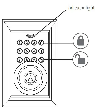 Programming Symbols
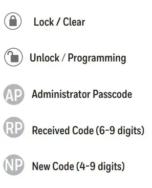
Programming Tips
Complete all the programming steps in the programming mode within 5 seconds.
Use the LOCK key to clear entries in case a wrong button is pushed.
Administrator Passcode:
(Admin Passcode is located on the Honeywell App under Lock Settings.)
Green
- Indicates successful programming step
- Indicates unlocking is successful
Red
- Indicates failed programming step
- Indicates locking is successful
Lock button
Lock – Use to lock door
Unlock button
- Unlock – Used to unlock the door
- Programming – Used in programming steps
Batteries (not included)
The electronic lock requires four (4) High-Quality AA Alkaline batteries. When all 4 batteries are installed in the correct position, you will hear 2 beeps and the keypad will illuminate blue. DO NOT TOUCH the keypad until the keypad stops illuminating.
VERY IMPORTANT
The lock must be connected to the App in order to program the keypad.
By default, the factory keypad passcode is 1234
Change the Administrator passcode AP so it can easily be remembered by you after connecting to a lock.
Once you connect the App to the lock, the factory keypad passcode will be changed to a new code, which can be found in the lock’s settings.
PROGRAMMING PHYSICAL KEYPAD
- TURN ON/OFF THE AUTO-LOCK FUNCTION
- Input the AP
- Green light and beep
- 5
- Input time (20 – 900 seconds, and 00 to turn off)
- Green light and beep
- SOUND OFF
- Input the AP
- Green light and beep
- 6
- 1
- Green light and beep
- SOUND ON
- Input the AP
- Green light and no beep
- 6
- 2
- Green light and beep
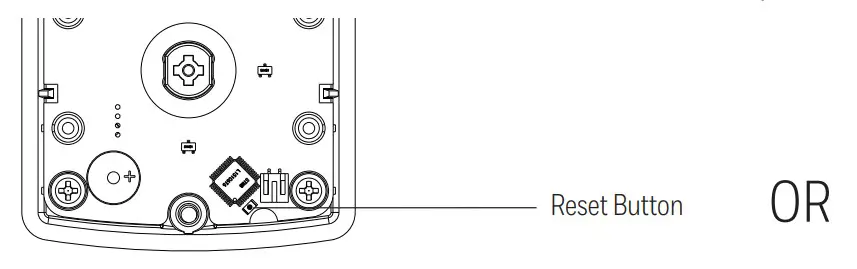
- RESTORE FACTORY SETTINGS
- Press the reset button on the PCB board until you hear one beep. Release, and then three seconds later you will hear a second beep after three seconds. This indicates that the lock has been reset to the Factory Settings. (Remove cover, The reset button is located inside the back panel, See image below)

- The Administrator of the lock deletes the lock from the App (Must be done near lock)
- Press the reset button on the PCB board until you hear one beep. Release, and then three seconds later you will hear a second beep after three seconds. This indicates that the lock has been reset to the Factory Settings. (Remove cover, The reset button is located inside the back panel, See image below)
- ADD ADMINISTRATOR
To add the administrator you must use the App. Press any button on the keypad to wake up lock in order to connect. - CUSTOMIZE PASSCODES RECEIVED FROM THE APP
- Input the AP
- Green light and beep
- 1
- Input RP
- NP
- Repeat NP
- Green light and beep
VERY IMPORTANT
In order to change a Passcode, the Passcode must have been sent from the App, and used by the Receiver.
- ENABLE/DISABLE AUTO-LOCK
Disable – While in Auto-Lock mode, unlock the door with the correct password, within 10 seconds you must turn the locking knob by hand to the locked position. Wait more than 2 seconds then turn the locking knob back to the unlock position. The Auto-Lock mode is now disabled.
Enable – While waiting more than 2 seconds, or press the button on the keypad. - VACATION MODE
- Input the AP
- – Green light and beep
- 10
- 1
- Green light and beep
- DISABLE VACATION MODE
- Press the button for 3 seconds
- Input the AP
- Green light and beep
TROUBLESHOOTING

CONSUMER ASSISTANCE
EMAIL: [email protected]
WEBSITE: www.honeywellsafes.com
ADDRESS: Consumer Assistance Dept.
LH Licensed Products, Inc., 860 East Sandhill Avenue Carson, CA 90746 USA
TELEPHONE: US/Canada 1-800-860-1677 Ext. 1801 (Toll-Free) Mexico 01-800-288-2872 After the English voice recording stops you must then enter 800-860-1677 to complete your call. (Toll-Free)
Australia 0011-800-5325-7000 (Toll-Free)
Germany/New Zealand 00-800-5325-7000 (Toll-Free) Other Countries XX*-310-323-5722 (Toll Charges Apply) XX*- Dial U.S. Country Code first
CALL CENTER HOURS: US/Canada 8 am – 5 pm (Pacific**) Mon – Fri (Subject to change)
CALL BACK HOURS: Other Countries 8 am – 5pm (Pacific**) Mon – Fri (Subject to change)
Pacific**- Local time in Los Angeles, CA, USA
* Insert correct Country Code
** Local Time based on Los Angeles California USA
INTERNATIONAL CALL-BACK HOURS:
If you need to speak with a consumer assistant and cannot contact us during the Call Center hours above, please send an email or leave a telephone message, including your Name, Telephone Number and the best time for us to contact you during the Call Back hours above and we will make our every effort to contact you and help answer any of your questions or concerns.
AUSTRALIAN CONSUMER LAW
Our goods come with guarantees that cannot be excluded under the Australian Consumer Law. You are entitled to a replacement or refund for a major failure and for compensation for any other reasonably foreseeable loss or damage. You are also entitled to have the goods repaired or replaced if the goods fail to be of acceptable quality and the failure does not amount to a major failure.
FCC COMPLIANCE
Regulatory Compliance
This product complies with standards established by following regulatory bodies:
Federal Communications Commission (FCC)
FCC
This device complies with Part 15 of the FCC rules.
Operation is subject to the following two conditions:
- This device may not cause harmful interference, and
- This device must accept any interference, including interference that may cause undesired operation
IMPORTANT! Changes or modifications not expressly approved by the manufacturer could void the user’s authority to operate the equipment.
WARRANTY
This product comes with a limited lifetime mechanical and finish warranty and a one year limited electronics warranty to the original residential consumer against defects in material and workmanship under normal use as long as the original residential purchaser occupies the residential premises upon which the product was originally installed.
ORIGINAL RESIDENTIAL CONSUMER
This warranty is not transferable, and applies to the original purchaser only, as long as the original purchaser occupies the residential premises upon which the product(s) was originally installed. Proof of purchase (original sales receipt) and ownership must accompany all warranty claims.
All non-homeowner purchasers (including purchasers for industrial, commercial and business use) are not covered under the terms of this warranty.
WHAT IS NOT COVERED
This warranty is null and void if the product was used for purposes for which it was not designed. This warranty DOES NOT COVER normal wear and tear of parts or damage resulting from any of the following: negligent use, misuse or abuse of the product, or use contrary to or in violation of written instructions provided by LH Licensed Products, Inc. Further, this warranty does not cover Acts of God, such as fire, flood, hurricanes and tornadoes. This warranty DOES NOT COVER scratches, abrasions, or deterioration due to the use of paints, solvents or use of cleaners containing abrasives, alcohol or other solvents, whether performed by a contractor, service company, or yourself. This warranty DOES NOT COVER product(s) used in commercial applications, used in common area applications, disassembly, repair or alteration by anyone other than LH Licensed Products, Inc., improper installation or exposure to extremes of heat or humidity. This warranty DOES NOT COVER any losses, injuries to persons or loss of property, general damages or costs, and shipping and freight expenses required to return product(s) to LH Licensed Products, Inc. LH Licensed Products, Inc. shall not be liable for any indirect, incidental or consequential damages of any nature relating to this lock. LH Licensed Products, Inc. is also not responsible for costs associated with removing or reinstalling the product.
ADDITIONAL TERMS
LH Licensed Products, Inc. does not authorize any person to create for it any obligation or liability in connection with the Product. LH Licensed Products, Inc.’s maximum liability here under is limited to the original purchase price of the Product. No action arising out of any claimed breach of this warranty by LH Licensed Products, Inc. may be brought by the original residential purchaser more than one (1) year after the cause of action has arisen.
Manufactured by:
LH Licensed Products, Inc.
860 East Sandhill Avenue
Carson, CA 90746
M8812309S 8812409S E V0
The Honeywell Trademark is used under license from Honeywell International Inc. and makes no representations or warranties with respect to this product.
www.honeywellsafes.com
FAQS
If the lock communicates over Bluetooth w/ my phone (not wifi), do i have to be within a certain distance or can I communicate from another state?
Yes you need to be less than 10 feet from lock. Not Wifi capable as far as I could make out. An expensive lock with poor documentation. If you can use a deadbolt electronic/digital lock thenmany long distance options
how many digits are required for the pin? 3? 4? x? thx
It requires a six digit code.
Are the keys back lit
Yes. After you push one they light up.
What is the setback for this lock?
Box states fits 2-3/8 in (35 mm) or 2-3/4 in (70 mm) back-sets
Does the person that I send the temporary or one-time code to have to have the app? Or does it send in a text?
You set the PIN, and tell them what it is.
They do not need the app to use the door lock, they input the code on the keypad.
Can you rekey this to match a master key used for other units?
You would need a kit that locksmiths carry
If it’s the hole on the door. No, it will not fit. You’ll have to drill a hole larger on the face of the door. It states 2-3/8” guide template or 2-3/4” backseat on the instructions.
No
Does this fit a 1.5-inch hole?
Near keypad. Is Bluetooth base.
Does your smartphone need to be near the keypad to add or delete codes? Can this be done remotely?
You can create and send permanent, temporary (timed) or one-time use Bluetooth ekeys and digital passcodes to anyone from anywhere with your smartphone.
Would I be able to lock/unlock if I’m not at home; for a child that’s locked out, housekeeper, neighbor, etc?
Yes, you can set up to 15 minutes after it is unlocked to lock itself.
Does this work with Alexa?
No
Does the keypad light up when pressed?
Yes, it does.


