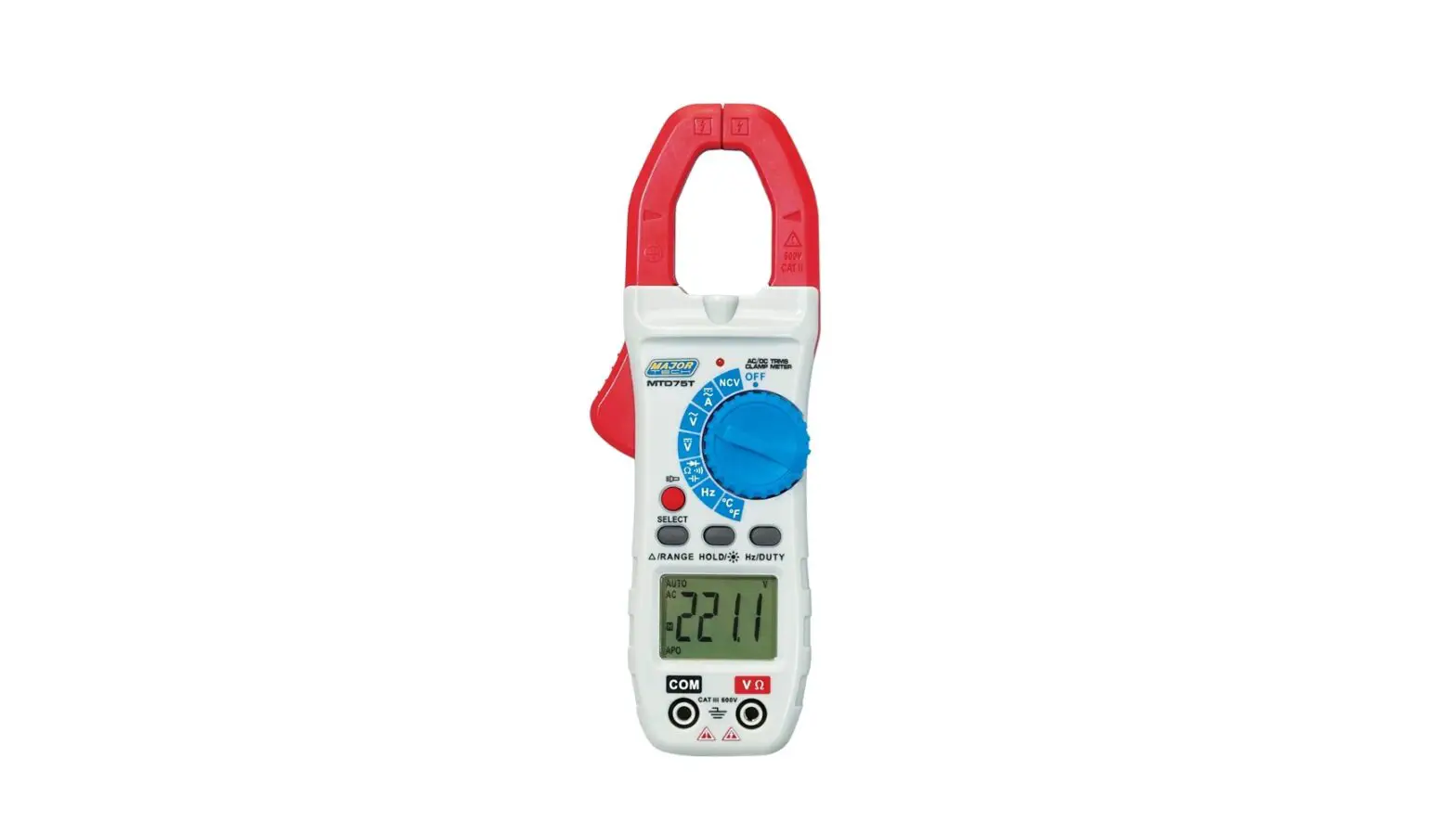
MAJOR TECH MTD75T 800A AC-DC True Rms Digital Clamp Meter Instruction Manual
SAFETY
lnternational Safety Symbols
![]() This symbol, adjacent to another symbol or terminal, indicates the user must refer to the manual for further information.
This symbol, adjacent to another symbol or terminal, indicates the user must refer to the manual for further information.
![]() This symbol, adjacent to a terminal, indicates that, under normal use, hazardous voltages may be present.
This symbol, adjacent to a terminal, indicates that, under normal use, hazardous voltages may be present.
![]() Double insulation.
Double insulation.
![]() Application around and removal from uninsulated hazardous live conductors is permitted.
Application around and removal from uninsulated hazardous live conductors is permitted.
Safety Notes
- Do not exceed the maximum allowable input range of any function.
- Do not apply voltage to meter when resistance function is selected.
- Set the function switch OFF when the meter is not in use.
- Remove the battery if meter is to be stored for longer than 60 days.
Warnings
- Set function switch to the appropriate position before measuring.
- When measuring volts do not switch to current/resistance modes.
- Do not measure current on a circuit whose voltage exceeds 600V.
- When changing ranges always disconnect the test leads from the circuit under test.
Cautions
- Improper use of this meter can cause damage, shock, injury or death. Read and understand this user manual before operating the meter.
- Always remove the test leads before replacing the battery or fuses.
- Inspect the condition of the test leads and the meter itself for any damage before operating the meter. Repair or replace any damage before use.
- Use great care when making measurements if the voltages are greater than 25VAC RMS or 35VDC. These voltages are considered a shock hazard.
- Always discharge capacitors and remove power from the device under test before performing Diode, Resistance or Continuity tests.
- Voltage checks on electrical outlets can be difficult and misleading because of the uncertainty of connection to the recessed electrical contacts. Other means should be used to ensure that the terminals are not “live”.
- If the equipment is used in a manner not specified by the manufacturer, the protection provided by the equipment may be impaired.
| Function | Maximum Input |
| A DC , A AC | 800A DC/AC |
| V DC, V AC | 1000V DC/AC |
| Resistance, Capacitance, Frequency, Diode Test, Temperature | 250V DC/AC |
Description
Meter Description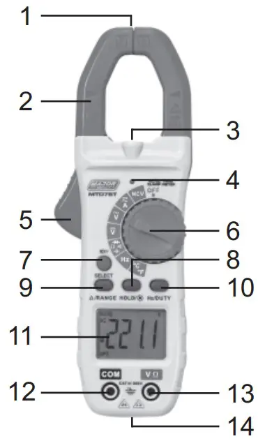
- NCV Test
- Current clamp
- LED Flashlight
- Non-contact AC voltage indicator light
- Clamp trigger
- Rotary Function switch
- SELECTOR mode range button
- Data Hold and Flashlight and LCD backlight button
- RANGE button and DCA Zero
- Frequency and % Duty Cycle button
- LCD display
- COM input jack
- V Ω Diode Continuity CAP TEMP Hz% jack
- Battery Cover
Display Icons
| Button | Operation Performed |
| Data Hold | |
| Minus sign | Negative reading display |
| 0 to 5999 | Measurement display digits |
| DCA Zero | |
| NCV | Non-Contact Voltage |
| APO | Auto Power Off |
| AUTO | Auto Range mode |
| DC | Direct Current/Voltage |
| AC | Alternating Current/Voltage |
| Low battery | |
| mV or V | Milli-volts or Volts (Voltage) |
| Ω | Ohms (Resistance) |
| A | Amperes (Current) |
| F | Farad (Capacitance) |
| Hz/% | Hertz (Frequency)/Percent(duty ratio) |
| °F and °C | Fahrenheit and Celsius units (Temperature) |
| n, m, μ, M, k | Unit of measure prefixes: nano, milli, micro, mega, and kilo |
| Continuity test | |
| Diode test |
General Specifications
| Basic Functions Range | |
| Clamp jaw opening | 28mm approx. |
| Display | 6000 Count (3-5/6 digits backlit LCD |
| Low Battery indication | is displayed |
| Over-range indication | |
| Measurement rate | 3 readings per second, nominal |
| Temperature sensor | Type K thermocouple 4mm terminals |
| Input Impedance | 10MΩ (VDC and VAC) |
| AC response | TrueRMS (AAC and VAC) |
| ACV Bandwidth | 2KHZ |
| Operating Temperature | 5°C to 40°C (41°F to 104°F) |
| Storage Temperature | -20°C to 60°C (-4°F to 140°F) |
| Operating Humidity | Max 80% up to 31°C (87°F) Decreasing linearly to 50% at 40°C (104°F) |
| Storage Humidity | <80% |
| Operating Altitude | 2000meters (7000ft.) maximum. |
| Battery | 2 x 1.5V AAA Battery |
| Battery life | Approx. 30h (backlight ON), Approx. 100h (backlight OFF) |
| Auto power OFF | After approx. 15 minutes |
| Dimensions | 123 (W) x 270 (D) x 39 (H)mm |
| Weight | 280g |
| Safety | For indoor use and in the requirement For double insulation IEC1010-1(2001): EN61010-2-030, EN61010-2-032, EN61010-2-033 Overv oltage Category III 600V, Pollution Degree 2. |
SPECIFICATIONS
AC True RMS Current
| Range | Resolution | Accuracy (% of reading + digits) |
| 60.00A | 0.01A | ±1.5% of rdg ± 5 digits |
| 600.0A | 0.1A | |
| 800.0A | 1A |
Over range protection: Maximum input 1000A
Accuracy specified from 5% to 100% of the measuring range
Frequency Response: 40Hz to 1kHz True RMS
DC Current
| Range | Resolution | Accuracy (% of reading + digits) |
| 0.00A | 0.01A | ±1.5% of rdg ± 5 digits |
| 600.0A | 0.1A | |
| 800.0A | 1A |
Over range protection: Maximum input 1000A
AC Voltage
| Range | Resolution | Accuracy (% of reading + digits) |
| 6.00V | 1mV | ±0.8% of rdg ± 5 digits |
| 60.0V | 10mV | |
| 600V | 100mV |
Input impedance 10MΩ. Overload protection 1000V AC RMS.
Frequency response 6000V at 40Hz to 1kHz (sine), other ranges 40/2kHz (all wave).
DC Voltage
| Range | Resolution | Accuracy (% of reading + digits) |
| 600mV | 0.1mV | ±1.0% of rdg ± 5 digits |
| 6.00V | 1mV | ±0.5% of rdg ± 5 digits |
| 60.0V | 10mV | |
| 600V | 100mV |
Input impedance 10MΩ. Overload protection 1000V RMS
Resistance
| Range | Resolution | Accuracy (% of reading + digits) |
| 600.0Ω | 0.1Ω | ±0.8% of rdg ± 5digits |
| 6.000kΩ | 1Ω | ±0.8% of rdg ± 1 digits |
| 60.00kΩ | 10Ω | |
| 600.0kΩ | 100Ω | |
| 6.000MΩ | 1kΩ | |
| 60.00MΩ | 10kΩ | ±1.0% of rdg ± 5 digits |
Input Protection: 250V DC or 250V AC RMS
Note:
a. On 600Ω range, short the test leads to measure lead resistance, then subtract the value from the real measurement
b. When measuring resistance over 1MΩ, it is normal that the reading reacts slowly, wait until reading is stable
Capacitance (Auto Ranging)
| Range | Resolution | Accuracy (% of reading + digits) |
| 6nF | 1pF | ± (5.0% rdg ± 10 digits) |
| 60nF | 10pF | ± (2.5% rdg ±5 digits) |
| 600nF | 100pF | |
| 6uF | 1nF | |
| 60uF | 10nF | |
| 600uF | 100nF | ± (5% rdg ± 10 digits) |
| 6mF | 1uF | |
| 60mF | 10uF |
Ensure capacitors are discharged before measuring value
Warning DO NOT apply voltage to this range
Frequency (Auto Ranging)
| Range | Resolution | Accuracy (% of reading + digits) |
| 10Hz | 0.01Hz | ± (0.5% rdg ± 4 digits) |
| 100Hz | 0.1Hz | |
| 1kHz | 1Hz | |
| 10kHz | 10Hz | |
| 100kHz | 100Hz | |
| 1MHz | 1kHz | |
| 10MHz | 10kHz |
Input Protection: 250V DC or 250V AC RMS
Input sensitivity >0.7V
Temperature
| Range | Resolution | Accuracy (% of reading + digits) |
| -40°C to | 1°C | <400°C: ±1.0% ± 5°C |
| +1000°C | ≥400°C: ±1.5% ± 15°C | |
| 0°F to | 1°F | <750°F: ±1.0% ± 5°C |
| +1832°F | ≥750°F: ±1.5% ± 15°C |
Sensor: Type K Banana Plug Thermocouple
Warning DO NOT apply voltage to this range
Diode & Continuity
| Function | Testing Condition | Reading |
| Diode | Forward DCA is approx. 0.8mA, open circuit Voltage MAX. 2.2V | Forward voltage drop of Diode |
| Continuity | Open circuit Voltage MAX. 2V | Buzzer makes a continuous sound while resistance is less than (50Ω) |
Input Protection: 250V DC or 250V AC RMS
Warning DO NOT apply voltage to Continuity range
OPERATION
NOTES: Read and understand all Warning and Caution statements in this operation manual prior to using this meter. Set the function select switch to the OFF position when the meter is not in use.
AC Current Measurements
WARNING: Ensure that the test leads are disconnected from the meter before making current clamp measurements.
- Set the Function switch to the A
 Range. If the approx. range of the measurement is not known, select Auto Range.
 - Press the
 /RANGE button to zero the meter display.
 - Use SELECT Button to select AC
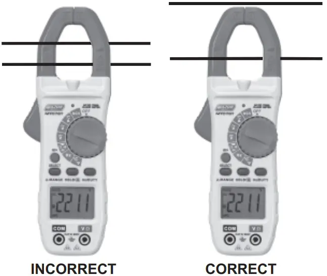
- Press the trigger to open jaw. Fully enclose only one conductor. For optimum results, center the conductor in the jaw.
- The clamp meter LCD will display the reading.

DC Current Measurements
WARNING: Ensure that the test leads are disconnected from the meter before making current clamp measurements.
- Set the Function switch to the A Range. If the approx. range of the measurement is not known, select Auto Range.
- Press the /RANGE button to zero the meter display.
- Use SELECT Button to select DC
- Press the trigger to open jaw. Fully enclose only one conductor. For optimum results, center the conductor in the jaw.
- The clamp meter LCD will display the reading.
AC Voltage Measurement
- Insert the black test lead into the negative COM terminal and the red test lead into the positive V/Ω terminal.
- Set the function switch to the V~ position.
- Connect the test leads in parallel to the circuit under test.
- Read the voltage measurement on the LCD display.
DC Voltage Measurement
- Insert the black test lead into the negative COM terminal and the red test lead into the positive V/Ω terminal.
- Set the function switch to the V
 position.
 - Connect the test leads in parallel to the circuit under test.
- Read the voltage measurement on the LCD display.
Resistance Measurement
- Insert the black test lead into the negative COM terminal and the red test lead into the positive V/Ω terminal.
- Set the function switch to the position
 .
. - Use SELECT Button to select Ω
- Touch the test probe tips across the circuit or component under test. It is best to disconnect one side of the device under test so the rest of the circuit will not interfere with the resistance reading.
- For Resistance tests, read the resistance on the LCD display.
Capacitance Measurement
WARNING: To avoid electric shock, discharge the capacitor under test before measuring.
- Insert the black test lead into the negative COM terminal and the red test lead into the positive V/Ω terminal.
- Set the function switch to the position .
- Use SELECT Button to select nF
- Touch the test probe tips across the circuit or component under test. It is best to disconnect one side of the device under test so the rest of the circuit will not interfere with the resistance reading.
- Capacitance value displayed on the LCD display.
Frequency Measurement
- Insert the black test lead into the negative COM terminal and the red test lead into the positive V/Ω terminal.
- Set the function switch to the Hz position.
- Touch the test probe tips across the circuit or component under test. It is best to disconnect one side of the device under test so the rest of the circuit will not interfere with the resistance reading.
- Frequency measurement can be read on the LCD display.
Temperature Measurement
- Set the function switch to the °C/°F position.
- Insert the Temperature Probe into the negative COM and the V/Ω positive jacks, observing polarity.
- Touch the Temperature Probe head to the device under test. Continue to touch the part under test with the probe until the reading stabilizes.
- Read the temperature on the display. The digital reading will indicate ambient temperature if no probe is inserted.
- Use the SELECT button to select °F or °C.
WARNING: To avoid electric shock, be sure the thermocouple probe has been removed before changing to another measurement function.
Continuity Measurements
- Insert the black test lead into the negative COM terminal and the red test lead into the positive V/Ω terminal.
- Set the function switch to the position.
- Use SELECT Button to select
 . The display icons will change when the SELECT button is pressed.
 - Touch the Test Probe tips across the circuit or component under test.
- If the resistance is <50Ω, the buzzer tone will sound.
Diode Measurements
- Insert the black test lead into the negative COM terminal and the red
test lead into the positive V/Ω terminal - Set the function switch to the position.
- Use SELECT Button to select
 . The display icons will change when the SELECT button is pressed.
 - Touch the test probe tips to the diode or semiconductor junction under test. Note the meter reading
- Reverse the test lead polarity by reversing the red and black leads. Note the reading
- The diode or junction can be evaluated as follows:
- If one reading displays a value (typically 0.400V to 0.900V) and the other reading displays OL, the diode is good.
- If both readings display OL device is open
- If both readings are very small or “0”, the device is shorted
Non-Contact AC Voltage Measurements
WARNING: Risk of Electrocution. Before use, always test the Voltage Detector on a known live circuit to verify proper operation
- Touch the probe tip to the hot (LIVE) conductor or insert into the hot (LIVE) side of the electrical outlet.
- If AC voltage is present, the detector red LED light will illuminate.
- a. NOTE: The conductors in electrical cord sets are often twisted. For best results, rub the probe tip along a length of the cord to assure placing the tip in close proximity to the live conductor.
- b. NOTE: The detector is designed with high sensitivity. Static electricity or other sources of energy may randomly trip the sensor. This is normal operation.
HOLD/Flashlight & LCD Backlight
To freeze the LCD reading, press the HOLD/![]() button. While data hold is active, the HOLD icon appears on the LCD. Press the HOLD/
button. While data hold is active, the HOLD icon appears on the LCD. Press the HOLD/![]() button again to return to normal operation.
button again to return to normal operation.
The LCD is equipped with backlighting for easier viewing, especially in dimly lit areas. Press the Select Key button for 3 seconds to turn the Flashlight and LCD backlight on. Press again for 3 seconds to turn the Flashlight and backlight off. The both work simultaneously.
Range
Press the RANGE key to activate the manual mode and to disable the Autorange function. The symbol “AUTO” disappears from the upper left part of the display. In manual mode, press the RANGE key to change measuring range: the relevant decimal point will change its position. ‘ The RANGE keyis not active in positions,![]() ,
,![]() , CAP, Hz%, Temp °C °F. In Auto range mode, the instrument selects the most appropriate ratio for carrying out measurement. If a reading is higher than the maximum measurable value, the indication “OL” appears on the display. Press and hold the RANGE key for more than 1 second to exit the manual mode and restore the Auto range mode.
, CAP, Hz%, Temp °C °F. In Auto range mode, the instrument selects the most appropriate ratio for carrying out measurement. If a reading is higher than the maximum measurable value, the indication “OL” appears on the display. Press and hold the RANGE key for more than 1 second to exit the manual mode and restore the Auto range mode.
Automatic Power OFF
In order to conserve battery life, the meter will automatically turn off after approximately 15 minutes. To turn the meter on again, turn the rotary function switch to the OFF position and then to the desired function range. To cancel the auto power off function, press SELECT button and turn on the power with the rotary switch at the same time. THE “APO” symbol will disappear from the LCD display.
Maintenance
WARNING: To avoid electrical shock, disconnect the meter from any circuit, remove the test leads from the input terminals, and turn OFF the meter before opening the case. Do not operate the meter with an open case.
Cleaning and Storage
Periodically wipe the case with a damp cloth and mild detergent; do not use abrasives or solvents. If the meter is not to be used for 60 days or more, remove the battery and store it separately
Battery Replacement
- When the LCD displays
 , please replace the battery to ensure correct readings
 - Remove the Phillips head screw that secures the rear battery door
- Open the battery compartment
- Replace the 2x 1.5V AAA battery, recommend Alkaline batteries for longer use
- Secure the battery compartment


Customer Support
MAJOR TECH (PTY) LTD
South Africa:![]() www.major-tech.com
www.major-tech.com![]() [email protected]
[email protected]
Australlia![]() www.majortech.com.au
www.majortech.com.au![]() [email protected]
[email protected]