hontzsch VA40 Transducers UFA – UVA Integrated Vane Wheel Sensors
Safety Symbols
Warning!
Failure to observe the instructions can result in serious injury and damage to property!
Important notice!
Non-observance can result in serious damage to the equipment or restriction in performance!
Safety Instructions
Danger to life, risk of injury and damage to material or property. Read the Operating Instructions carefully before initial operation.
Observe general safety precautions as well as those included in various sections of these Operating Instructions.
Hazard risks
- non-observance of the Operating and Safety Instructions
- modifications to the device by the customer
- handling the device outside the specified operating conditions
- handling the transducers outside the specified operating conditions
- use of unsuitable power supplies and peripheral devices
- improper use of the device
Prevention of voltage hazards:
- use only the dedicated adapter plug for the mains supply
- make sure that the PC is correctly connected to the mains (earthed safety socket, earthing) when using a USB connection
- when connecting analog outputs or inputs to peripheral devices make sure that these are correctly connected to the mains (earthed safety socket, earthing)
Danger when installing the sensors in pressurized pipelines:
- sensors for use in pressurized pipelines are to be inserted or retracted only in depressurized con-ditions; non-observance may result in serious injuries to personnel
- when installing or removing under pressure, the appropriate protective equipment must be used, e.g. ball valve and probe guide pieces with chain guard or spindle probe guide pieces
Intended Use
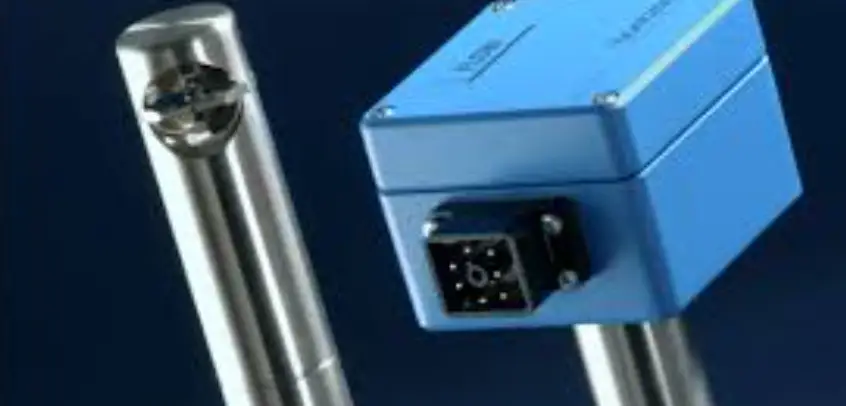
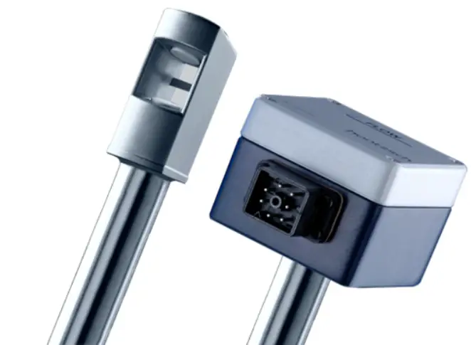
Transducers UFA and UVA are instruments for measuring flow velocity and flow rate:
UFA for use with vane wheel flow sensors FA or FAR and measuring tubes FA Di or FAR Di and UVA for use with vortex flow sensors VA40 and measuring tubes VA Di. These instruments are designed for industrial Application. The AS80 is an aluminium housing in protection class IP65.
The manufacturer is not liable for damage caused by improper use and/or non-compliance with the regula-tions.
Do not carry out any structural modifications to the transducers.
Always follow the instructions on the type plate, especially the information regarding supply voltage.
Operating Safety
All steps described below must be carried out by qualified personnel only!
Please read the Operating Instructions carefully before unpacking theequipment!
Safety can only be guaranteed if the equipment is operated in accordance with the regulations. Improper handling can result in serious injury and damage to property.
Scope of Delivery
- Transducer UFA or UVA integrated in the connection housing of the FA or VA flow sensors
- Operating Instructions Flow Sensor FA or VA, data sheet flow sensor FA or VA with integrated transducer UFA or UVA
- CD-ROM with PC configuration software UCOM (optional)
- Programming adapter GO 070 / RS232 for PC connection COM port (optional)
- USB adapter in addition to programming adapter GO 070 / RS232 (optional)
- Cable socket GO 070
Please check that everything listed in the Delivery Note / Technical Data Sheet is included in the delivery.
Description, Type Plates
One of the following type plates (or similar) can be found on the connection housing: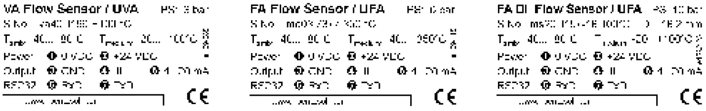
- VA Flow Sensor vortex flow sensor VA40
- FA Flow Sensor vane wheel flow sensor
- FA Di Flow Sensor vane wheel measuring tube
- UVA : transducer for vortex sensors VA
- UFA : transducer for vane wheel sensors FA
- PS max. permissible pressure
- S.No. serial number with max. temperature of the medium
- Di inside diameter Di of the measuring tube
- Tamb ambient air temperature range
– 40…+80 °C
– 30…+80 °C, only for type VA40/21,3 … GK … ZG10 sensors
– 5…+50 °C, with ‘LCD display’ option - Tmedium : temperature range of medium
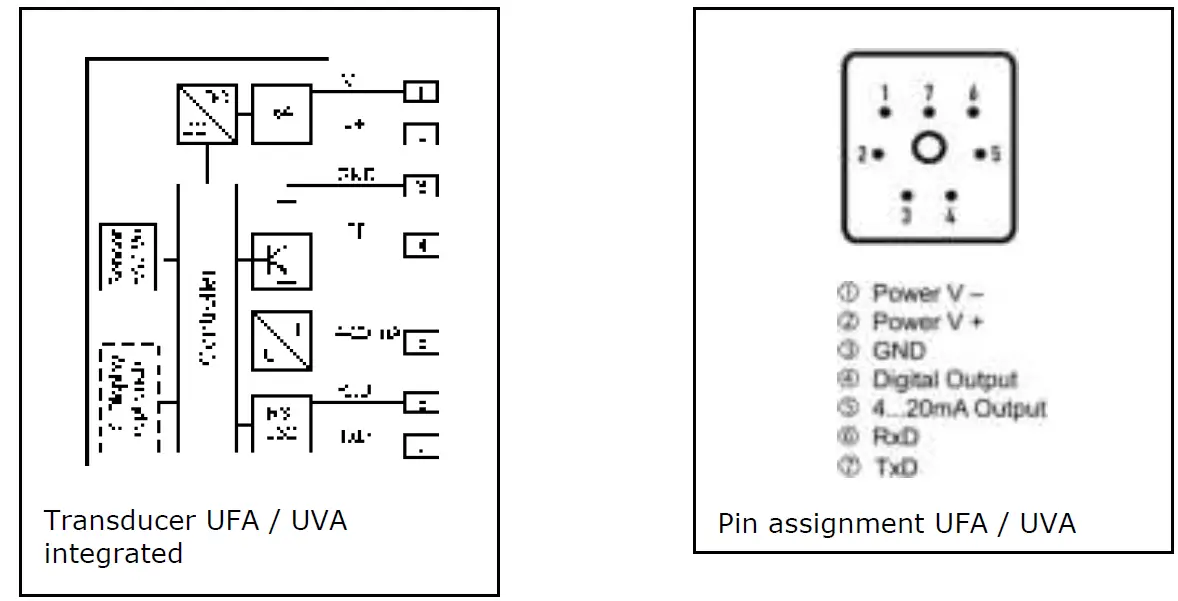
Pin assignment of cable socket GO 070:
- Power 1 : 0 VDC = supply voltage 0 VDC
2 : +24 VDC = supply voltage +24 VDC - Output 3 : GND = reference potential
4 : F = digital output open-collector (internally connected to GND)
5 : 4…20 mA = current output 4-20 mA - RS232 6 : RxD = serial interface
7 : TxD = serial interface
(GND = reference potential)
Technical Specifications
Conformity with Standards
Transducers UFA / UVA are manufactured according to the best available technology, are safe and reliable and comply with the relevant regulations, EU directives and standards.
Storage Conditions
Storage conditions: -30 to +70 °C
Operating Conditions
Ambient air temperature of connection housing when in use : -40 … +80 °C
-30 … +80 °C, only for type VA40/21,3 … GK … ZG10 sensors
with optional LCD display : -5 … +50 °C
protection class : IP65
mounting attitude no restrictions
Housing and Connection
- protection class housing IP65
- material aluminium
- external dimensions L/W/H = 80/80/60 mm
- connection cable socket GO 070 with terminals for strands with cross-section 0.25 … 1.0 mm²
Electrical Data
- Supply voltage, mains supply 24 V DC (20 … 27 V DC), power < 3 W
The mains supply is electrically isolated from the UFA/UVA outputs. - Analog output : 4 … 20 mA = 0 … x m/s (or m³/h)
4 … 20 mA = -x … 0 … +x m/s (or m³/h) with FAR function configurable.
Terminal value x configurable / resistance max. 400 Ohm - Digital output : (open-collector transistor), max. 50 mA / 27 V DC, configurable as limit value v, quantity pulse or ±direction of flow
- RS232 interface : for connection with PC programme UCOM
- Accessible by unscrewing the housing cover:
Connection for optional LCD display : flat ribbon cable with 10-pin cable socket Do not plug in or out when live!
Measurement Uncertainty
Recording the measurement frequency (at 1000 Hz) : <0.1%
Analog output (terminal value) <0.15%
Linearity error <0.1%
Temperature coefficient <20 ppm/K (at 25 °K temperature difference equivalent to <0.05%)
Installation
The current European Specifications for Assembly, the recognised standards of good practice and this Operating Instructions apply.
Block Diagram and Pin Assignment
Wiring Diagrams
Electrical connection must be carried out according to the appropriate wiring diagram.
Faulty connection can cause damage to the electronics.
Do not install or wire up the transducer under mains voltage. Non.compliance can cause damage to the electronics.
In this connection and depending on the configuration of the equipment, one of the following wiring dia-grams must be taken into account. Wiring diagrams for measuring systems in customer-specific design will be supplied separately.
Power supply
Before connecting please check that the power supply is within the specification.
The type plate with all relevant information can be found on the connection housing of the flow sensor.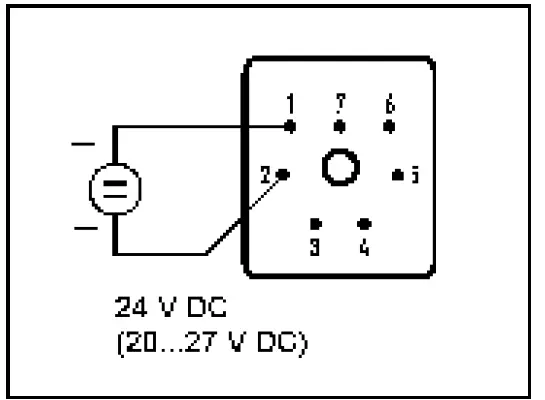 Analog output v
The terminal value of the analog output can be configured with the PC software UCOM via the RS232 inter-face. The factory-programmed values can be found in the accompanying documents.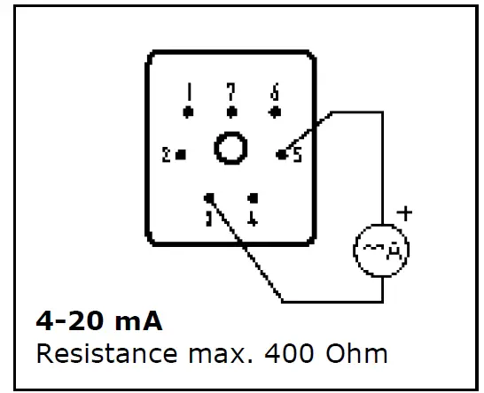 Digital output (open-collector-transistor)
The digital output is an open-collector transistor output, internally connected to GND.
The function of the digital output and the corresponding setting parameter are configurable using the UCOM software via the RS232 interface. The factory-programmed settings can be found in the parameter printout.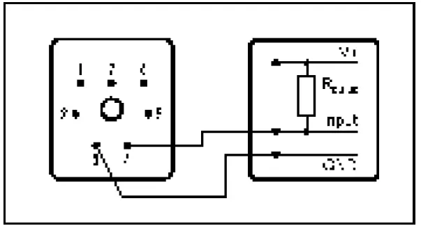 The reference potential terminal (3) of the UFA/UVA is connected to the GND terminal of the data logging. The open-collector transistor output (4) is connected to the input of the data logging, to which a pull-up resistor for internal supply voltage of the data logging must be connected (with 24 V as a rule 5…10 kOhm).
The limit values for the digital output are: max. 50 mA / max.27 VDC.
Note: If the same voltage source is used for the UFA/UVA as for the internal supply for the data logging, then the electrical isolation between the supply voltage and the UFA/UVA outputs is deactivated.
RS232 interface
To connect the RS232 interface, plug the programming adapter into the UFA/UVA. The transducer is powered by the adapter.
Connection to a PC is via a COM port or with an optional USB adapter.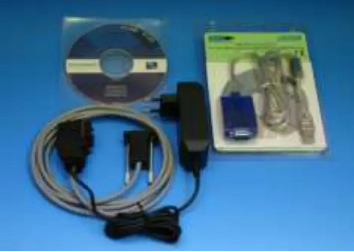 Optional LCD display
optional LCD in the housing cover  LCD connection with cover open
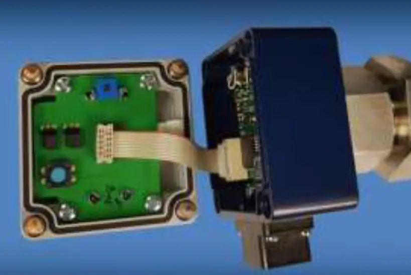 The flat ribbon cable with the 10-pin connector should not be plugged in or out when live! Risk of damage to equipment!
Visible are the potentiometer for the LCD display, the reset button for the quantity counter, the jumpers m/s-m³/h and A-B
Functional Description
UFA transducers are designed for connecting to vane wheel probes FA and FAR (directional sensing) and vane wheel measuring tubes FA Di and FAR Di (directional sensing) for measuring flow velocity or flow rate of air/gases and water/liquids.
UVA transducers are designed for connecting to vortex sensors VA for measuring flow velocity or flow rate of air/gases.
The signal frequency generated from the flow sensor is converted to a linear analog output signal 4-20 mA. The analog terminal value is configurable.
When logging directional sensing data, the zero point can be selected in the middle of the analog range, or display of flow direction takes place with the aid of the digital output:
- for FA and FAR*: 4 … 20 mA 0 … x m/s (or m³/h)
- for FAR: 4 … 12 … 20 mA -x … 0…+x m/s (or m³/h)
- for VA: 4 … 20 mA 0 … x m/s (or m³/h)
* for FAR sensors configuration of the digital output (see under): ±direction of flow
The actual velocity / actual flow rate can be converted to standard velocity / standard flow rate by enter-ing the parameters ‘temperature’ and ‘pressure’. Working temperature and pressure should be constant.
A digital output (open-collector transistor) can be configured for 1 of 3 different functions:
- as limit value for the flow velocity or flow rate:
flow velocity < or = limit value: open-collector transistor inactive
flow velocity > limit value: open-collector transistor active - as quantity pulse for quantity measurement:
max. pulse repetition frequency 1 Hz per unit of volume,
configurable, e.g. 1 pulse per 1, 10 or 100 (norm)-m³ or (norm)-litre pulse duration 0.5 s (with FAR sensors: configurable for ‘+’ or ‘-‘ amounts) - as ±direction of flow ** (FAR sensors only):
+ direction: open-collector transistor inactive
– direction: open-collector transistor active
** analog output (see above) is then absolute value of flow only, without direction
Self diagnosis according to NAMUR NE43:
No error analog output = 4 mA (flow velocity = 0)
analog output 4 mA (flow velocity > 0)
Error : analog output < 3.6 mA
Monitoring of power supply, data logging, sensor interface, parameter settings (see under 16 Troubleshooting)
PC serial port RS232
for changing calibration data and setting parameters.
Connect programming adapter GO 070 (optional) to the UFA/UVA transducer, then plug in the adapter. Connect sub-D to the PC RS232 socket.
If PC connection is via USB, then an optional available USB / RS232 interface converter must be inserted.
Changes to the settings can now take place after starting the PC programme UCOM (optional) (see under 9 Settings).
Optional LCD display in housing cover: 2 x 16 digit, character height 3 mm.
Display line 1 instantaneous value velocity or flow rate.
Display line 2 ‘quantity counter’ or ‘error code’.
Display line 1:
- m/s-m³/h = m/s and A-B = any: velocity in (N)m/s *
- m/s-m³/h = m³/h and A-B = A: flow rate in (N)m³/h
- m/s-m³/h = m³/h and A-B = B: flow rate in (N)lt/h **
* standard values (N) only when parameter ‘switching v/NV’ =1 (see under 9 Settings) ** only when diameter Di < 75.0 mm, otherwise display in (N)m³/h
Display line 2:
Quantity counter in m³ with 0 … 3 decimal places
(see under 9 Settings; parameter ‘switching pulse m³(cbm) / l (litre)’ and
parameter ‘m³ (cbm) / l (litre) per pulse’ and
parameter ‘decimal places quantity display’)
with error : error 01 = parameter error
error 02 = sensor error
Reset button in the housing cover: see Fig. 3, under 7.2.5 in housing cover
Reset the quantity counter by pressing the reset button for more than 3 seconds.
Settings
The following setting parameters can be read using the PC software UCOM and are also alterable. The customer-specific settings are shown on the parameter print-out, which is included in the documents.
Initial Operation
(Pay attention to 7.2.1 Power supply)
(Pay attention to 7.2.2 Analog output v)
On connecting the supply voltage:
no flow at sensor: the analog output sends a value of 4 mA (or 12 mA depending on configuration with FAR sensors, see under 8 Functional Description)
flow at sensor: the analog output sends an analog value deviating from the zero flow conditions (see above).
Please find operation instructions PC software UCOM in document U385.
Operation
(see under Operating conditions) (see under Electrical Data)
Shut-down, Dismantling
Before disconnecting the cable, please ensure that the supply voltage is switched off.
Inspection
see under Functional Description, Self diagnosis
Maintenance
Only use cleaning agents which dry without leaving any residue and which are compatible with the housing materials.
Any repair work is to be carried out solely by Höntzsch GmbH & Co. KG.
Meaning of LEDs on the circuit board
| LED | Description |
| LED red on | parameter error |
| LED yellow on | sensor error |
Troubleshooting
| Fault | Cause | Troubleshooting |
| analog output = 0 mA | no power supply | check connecting cable, measure voltage at connecting terminals |
| transducer electronics faulty | return to factory | |
| analog output = error (<3.6 mA) | parameter error | check parameter using UCOM software, save new checksum (or return to factory) |
| transducer electronics faulty | return to factory | |
| analog output = 4 mA, no measured value | sensor contaminated | clean sensor according to instructions |
| profile factor set at 0.000 | set profile factor to relevant nominal diameter and sensor type | |
| measured value too low | sensor contaminated | clean sensor according to instructions |
| profile factor setting too low | set profile factor to relevant nominal diameter and sensor type | |
| input/output section too short | change sensor position, improve flow conditions with a flow rectifier | |
| rotational flow | reposition sensor in flow direction, install flow rectifier | |
| vortex VA sensors: reduced acoustic coupling in the sensor elements as a result of intense vibration or powerful impact | return sensor to factory for performance test | |
| burden at current output is greater than specified in the Technical Data Sheet result- ing in correct output values in the lower range and no longer increasing values at the top end of the measuring range | reduce resistance | |
| incorrect scaling of analog output | check setting and amend if necessary | |
| measured value too high | profile factor set too high | set profile factor to relevant nominal diameter and sensor type |
| EMC problem | see reference to electromagnetic compatibility (EMC) |
Returns
When returning sensors, these should be cleaned thoroughly according to the instructions. A hazard warn-ing or declaration of no objection must be supplied for substances which have been in contact with the sensor or possibly infiltrated the cavities in the sensor. If adhesion of hazardous substances cannot be ruled out, then detailed safety measures to be taken when handling the equipment must be itemised.
Disposal
The customer should assume the duty to dispose of the equipment at his own expense and according to statutory provisions (e.g. ElektroG in Germany).
Replacement Parts
Integrated transducers UFA /UVA have no replacement parts.
An electronic self-restoring fuse is used.
Declaration of Conformity, Declaration of Incorporation
We
Höntzsch GmbH & Co. KG Gottlieb-Daimler-Str. 37 D-71334 Waiblingen
bearing sole responsibility, hereby declare that the product
Transducer UFA / UVA in AS80 housing
referred to in this declaration, is in conformity with the following standards or normative documents:
| Provisions of the Directive | Reference and date of issue |
| 2014/30/EU: Electromagnetic Compatibility | EN 61000-6-4 EN 61000-6-2 |
| 2014/68/EU: Pressure Equipment Directive | |
| 2006/42/EC: Safety of Machinery | |
| Safety requirements for electrical equipment for measurement, control, and laboratory use | EN 61010 |
Instruction Manual Flow Sensors Category 3G and 3D
Failure to comply with the specifications of the operating manual can result in an explosion.
Apparatus
- Vane wheel flow sensors FA and measuring tubes FA Di with integrated or separate evaluation unit and optional integrated temperature probe Pt100
- Vortex flow sensors VA40 and measuring tubes VA Di with integrated or separate evaluation unit and optional integrated temperature probe Pt100
- Thermal flow sensors TA10 and measuring tubes TA Di with integrated or separate evaluation unit
This apparatus is designed for measuring the flow velocity and flow rate of gases in areas in which category 3G or 3D equipment is required.
During normal operation within the boundaries of the technical specifications the equipment is safe and does not generate sparks. Provision for self-heating does not need to be made in the case of vane wheel and vortex sensors. This also applies to thermal sensors in category 3G. The maximum additional surface temperature for category 3D areas is 135 °C.
Do not use the sensors
- in areas in which category 1G or 2G apparatus is required
- in areas in which category 1D or 2D apparatus is required
Safety Precautions
General
Hazard risks:
- modifications to the device by the customer
- handling the device outside the specified operating conditions
- handling the sensors outside the specified operating conditions
- improper use of the equipment
Danger when installing the sensors in pressurized pipelines:
- sensors for use in pressurized pipelines are to be inserted or retracted only in depressurized conditions; non-observance may result in serious harm to personnel
- when installing or removing under pressure, the appropriate protective equipment must be used,
e.g. ball valve and probe guide pieces with chain guard or spindle probe guide pieces
The medium container for the measurement gases must be insulated in a way that it is ensured that the electronics housing of the apparatus does not assume a higher temperature than the aforementioned maximum ambient temperature. The radiation and convection heat has to be considered also.
Use in potentially explosive atmospheres
Danger when use of the device in potentially explosive atmospheres:
- The flow sensors may only be used in areas specified for category 3G (zone 2) or category 3D (zone
22) apparatus. - The apparatus is to be connected to the local equipotential bonding system according to the currently valid regulations. The earth terminal is designed for cross-sections of 1,5 … 4 mm² mm². Use a cable lug. The torque for fixture to the earth terminal must amount to 2 … 3 Nm.
- If severe variations in temperature are to be expected, the device should be left to adapt to the ambi-ent temperature for at least one hour before use to avoid problems with condensation.
- The housing cover may only be opened and connection cables may only be connected or disconnected after the supply voltage has been disconnected.
- Instrument sensors with a separate evaluation unit may only be connected or disconnected when voltage-free. Protect the connection cables against opening.
- Before starting measurement in an explosive atmosphere, check whether the housing cover has been screwed down correctly.
- Mechanical shocks are to be avoided.
- Damaged instruments must not be used. This also applies to damage on the housing.
- The connection cable used must be approved for the temperature range of the evaluation electronics as a minimum.
- Any covering of dust on the electronic housing may not exceed 5 mm.
- Only the manufacturer’s cable glands ducts included in the scope of delivery or permitted, identical cable glands may be used.
- TA10C sensors may only be operated with a connection cable supplied by Höntzsch.
- The electronic housing must be protected from strokes and shocks.
Category 3G and category 3D vane wheel flow sensors FA and vortex flow sensors VA listed in chapter 1 are to be used solely in areas in which the ambient temperature range for the electronic housing does not exceed -20 to +50 °C. For sensors with integrated LCD display the ambient temperature range is limited from -5 to +50 °C. Consult the information in the appendant technical documentation.
Category 3G and category 3D thermal flow sensors TA listed in chapter 1 are to be used solely in areas in which the ambient temperature range for the electronic housing does not exceed -20 to +50 °C.
Category 3G apparatus listed in chapter 1 is to be used solely in areas with the temperatures marked on the type plate for the measuring medium and ambient atmosphere and for the maximum permissible overpressure.
The maximum permissible surface temperature for vane wheel and vortex sensors in category 3D areas is the maximum temperature of the medium and for thermal sensors 135 °C in addition to the maximum temperature of the medium. The maximum permissible temperature of the medium can be checked on the type plate and corresponding technical documents.
VAT and FT probes may be used in category 3G or 3D solely with a Höntzsch-approved evaluation unit specifically for these probes. Other combinations and categories are not permissible. Always check that the sensor is connected correctly. A wrongly connected sensor can increase the risk of explosion.
Technical Data
Marking:
Explosion protection: vane wheel sensors FA and vortex sensors VA
Ex ec IIC T6 Gc X
Explosion protection: thermal sensors TA
Ex ec IIC T4 Gc X
Marking:
Explosion protection: vane wheel sensors FA and vortex sensors VA
Ex tc IIIC TX Dc X
Explosion protection: thermal sensors TA
Ex tc IIIC T135°C Dc X
X: There are certain special factors to be observed for applications in explosive atmospheres (see chapter 2.2)
Electrical Data
For power supply, power input, current consumption, refer to the details on the type plate and corresponding technical documents.
Installation
The current European Specifications for Assembly, the recognised standards of good practice and this Instruction Manual apply.
We recommend a cable with a 4 … 6 mm² cross section for connection to the earth terminal. Use a cable lug.
The earth terminal must be tightened with a torque of 2 … 3 Nm.
Cleaning / Maintenance
Sensors should be cleaned at regular intervals.
Any other maintenance or repair work is to be carried out solely by Höntzsch GmbH & Co. KG.
Declaration of Conformity, Declaration of Incorporation Category 3G and 3D for
- V ane wheel flow sensors FA and measuring tubes FA Di with integrated or separate evaluation unit and optional integrated temperature probe Pt100
- Vortex flow sensors VA40 and measuring tubes VA Di with integrated or separate evaluation unit and optional integrated temperature probe Pt100
- Thermal flow sensors TA10C and measuring tubes TA Di with integrated or separate evaluation unit
We,
Höntzsch GmbH & Co. KG Gottlieb-Daimler-Str. 37 D-71334 Waiblingen
bearing sole responsibility, hereby declare that the above-mentioned products referred to by this declaration are in conformity with the following standards or normative documents:Provisions of the Directive Reference and date of issue 2014/34/EU: Equipment and Protective Systems in EN 60079-0: 2018 Potentially Explosive Atmospheres EN 60079-7: 2015 EN 60079-31: 2014 2014/30/EU: Electromagnetic Compatibility EN 61000-6-4: 2007 + A1: 2011
EN 61000-6-2: 2006 + Corrigendum 1: 20112014/68/EU: Pressure Equipment


