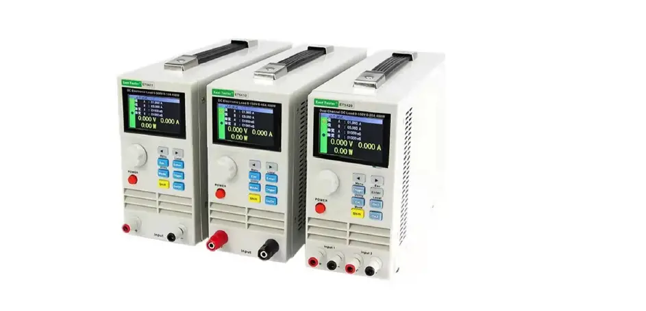
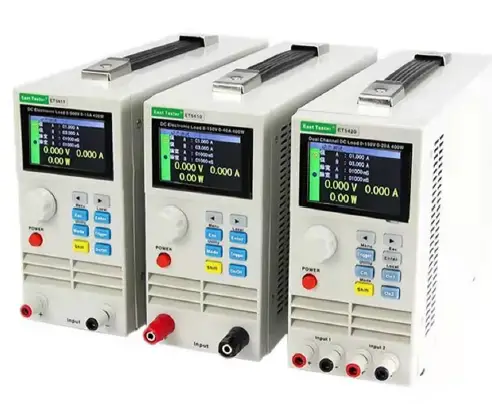
 East Tester Single-Channel Programmable DC Electronic Load
Product Basic Function
ET54 series DC programmable electronic load provides 1mV/10mV, 1mA/10mA high resolution and precision with superior performance. It is equipped with 12 common modes and complete test functions, which can be widely used in the charger, switching power supply, linear power supply, battery and other production line testing.
Key Features:
- User-friendly Design:
- It adopts a 2.8-inch TFT LCD screen with rich display contents;
- The operation process is simple and convenient, and with a visual interface display system, it is easy to get started.
- Key lock function to prevent misoperation;
- High-performance load:
- It provides CC, CV, CR, CP and CC+CV, CR+CV several basic measurement modes;
- It provides professional battery tests;
- It provides professional LED tests;
- The Tran test mode can test the dynamic output performance of the power supply;
- The scan test mode can test the continuity of power output within a certain range;
- The list test mode can simulate a variety of loading status changes;
- The short circuit test can be used to simulate load short circuit;
- Support external trigger input (DB9 interface is required);
- Built-in buzzer alarm;
- Maintain data storage in case of power failure;
- Remote operation via USB, RS-232 (optional) or 485 (optional) interfaces;
- With PS2 interface, and supports external keyboard for data value setting;
- Multiple safety protection:
- It provides overcurrent, overvoltage, overpowers, over temperature protection. The overvoltage and overcurrent parameters can be set flexibly, so as to effectively protect the load;
- It has an intelligent fan speed control function, which can effectively reduce fan noise when it is working.
- With input polarity reverse promptly;
General technical specifications:
- Power supply voltage: 220Vac±10%, 110Vac±10%, 45-65Hz
- Display: 2.8-inch TFT LCD screen with a resolution of 400×240
- Operating temperature: 0℃ to 40℃
- Storage temperature: -10℃ to 70℃
- Relative humidity: < 80%
- Interface: standard USB, optional RS232(or 485)
- Size: 90mm×190mm×300mm (width × height × depth)
Standard accessories:
- Three-core power cord 1
- Power fuse 2
- User manual 1
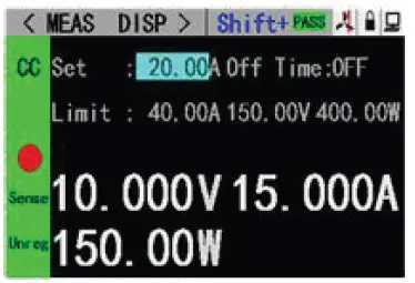
Front panel LCD display
Front panel key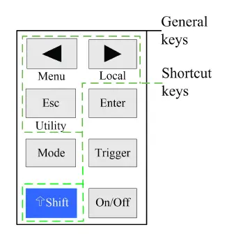
Key description
| General keys | Shortcut keys | ||
| Mode | Mode selection key | Shift+Menu | Parameter settings for non-basic mode. |
| On/Off | Channel switch key | Shift+Utility | System general settings |
| Esc | Back key | Shift+Local | Remote/local switch |
| Trigger | Trigger Key | ||
| Enter | Enter key | ||
| ◀ ▶ | Keys for moving the cursor left or right. | ||
| Shift | Shift key | ||
Function operating
To ensure stable and safe operation of the load and the source to be measured, make sure that the load and the source to be measured are connected in a red-positive and black-negative manner before using the load to test the source to be measured. After that, first, turn on the power output, and then turn on the load.
Remote/local switching
When the load is in remote operation mode, the corresponding icon will be displayed on the top of the interface. At this time, the interface is locked, and the status and operation of the instrument can be controlled by the commands of the upper computer, or switch back to the local operation mode by pressing[Shift]+[▶ ](Local) on the panel.
System Setup
Press [Shift] + [Esc](Utility) to enter the system menu interface, as shown in the figure. 2.2.1. Rotate the knob to select and enter the corresponding sub-menu. The operation of language setting, restore factory setting and start settings can be completed in the system setting interface, as shown in figure 2.2.2.
Operating instructions: 1. Select the operation option by rotating the knob. 2. Press [Enter] to enter the sub-menu interface or switch the contents of the operation option. 3. Press [Esc] to return to the previous interface.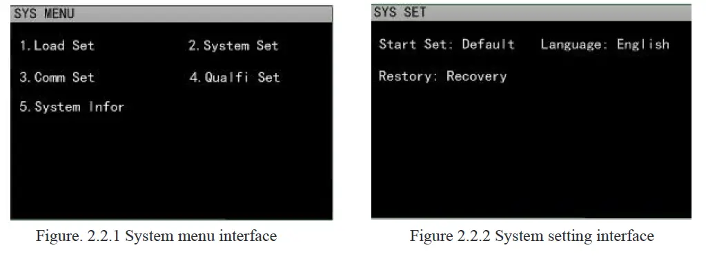
Load Setup
The load setup interface can be entered through the system menu, as shown in figure 2.3. The load range, limit value, off-delay and other related settings can be completed in this interface. Operating instructions: 1. Select the operation option by rotating the knob. 2. Press[Enter]to switch set options for non-numeric parameters. 3. As for the setting of numeric parameters, press [Enter] to enter the edit mode, and press the direction keys to select the corresponding number of digits, and then rotate the knob to adjust the value. Press [Enter] to confirm the input. 4. Press【Esc】to return to the previous interface.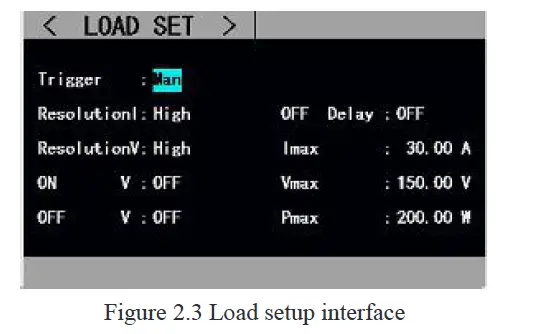
Basic Mode
The electronic load can work in the following basic measurement modes: constant current mode (CC), constant voltage mode (CV), constant resistance mode (CR), constant power mode (CP), constant current to constant voltage mode (CC+CV), constant resistance to constant voltage mode (CC+CR). The parameter settings for the above six modes can be done in the measurement interface. In addition, press [Mode] on the main interface of any mode to enter the mode selection interface, as shown in figure 2.4.
Operating instructions: 1 Select the operation option by rotating the knob. 2. Press [Enter] to confirm the selected mode. 3. Press [Esc] to return to the previous interface.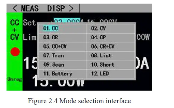
Constant Current Mode
In constant current mode, the electronic load consumes a constant current regardless of whether the input voltage changes or not.
Operating instructions: 1 Select the operation option by rotating the knob. 2. Parameter settings. Press [Enter] to enter the edit mode and press the direction keys to select the corresponding number of digits. Rotate the knob to adjust the value and press [Enter] or [Esc] to exit the edit mode. 3. Press the corresponding [On/Off] to turn on the load.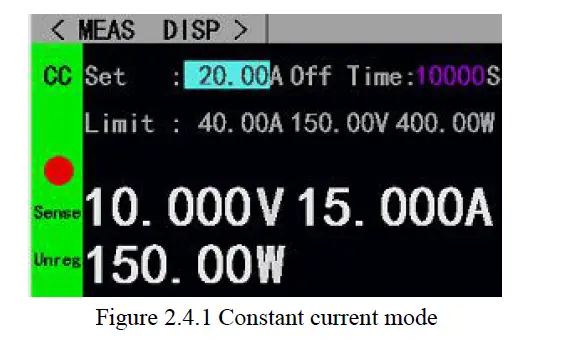
Constant voltage mode
In constant voltage mode, the electronic load will consume enough current to keep the input voltage at the set voltage.
Operating instructions: 1 Select the operation option by rotating the knob. 2. Parameter settings. Press [Enter] to enter the edit mode and press the direction keys to select the corresponding number of digits. Rotate the knob to adjust the value and press [Enter] or [Esc] to exit the edit mode. 3. Press the corresponding [On/Off] to start the mode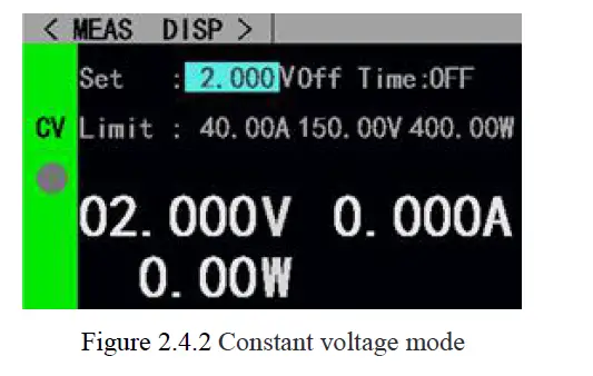
Constant resistance mode
In constant resistance mode, the load is equivalent to a constant resistance, and the load will consume a current that varies with the input voltage.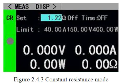
Constant power mode
In constant power mode, the load consumes constant power. When the input voltage changes, the load will adjust the current accordingly to keep the consumed power at the set power value.
Operating instructions: 1 Select the operation option by rotating the knob. 2. Parameter settings. Press [Enter] to enter the edit mode and press the direction keys to select the corresponding number of digits. Rotate the knob to adjust the value and press [Enter] or [Esc] to exit the edit mode. 3. Press the corresponding [On/Off] to start the mode.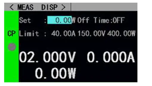
Constant current to constant voltage mode
The constant current to constant voltage mode is to prevent the source to be measured from being damaged by overcurrent discharge. In this mode, when the source to be measured cannot output the current value set by the load, it will automatically switch from constant current mode to constant voltage mode.
Operating instructions: 1 Select the operation option by rotating the knob. 2. Parameter settings. Press [Enter] to enter the edit mode and press the direction keys to select the corresponding number of digits. Rotate the knob to adjust the value and press [Enter] or [Esc] to exit the edit mode. 3. Press the corresponding [On/Off] to start the mode.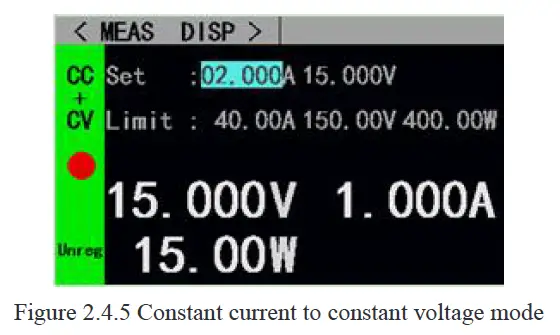
Constant resistance to constant voltage mode
The constant resistance to constant voltage mode is to prevent the source to be measured from being damaged by overcurrent discharge. In this mode, when the source to be measured cannot output enough current to maintain the set resistance, the load will switch from constant resistance mode to constant voltage mode.
Operating instructions: 1 Select the operation option by rotating the knob. 2. Parameter settings. Press [Enter] to enter the edit mode and press the direction keys to select the corresponding number of digits. Rotate the knob to adjust the value and press [Enter] or [Esc] to exit the edit mode. 3. Press the corresponding [On/Off] to start the mode.
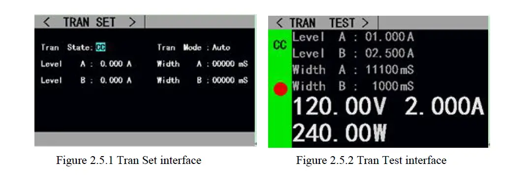
Tran Test
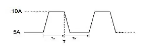
Tran test can be switched back and forth between two currents or voltages set by the load. This function can be used to test the dynamic characteristics of the power source. Before starting the Tran test, relevant parameters of Tran test should be set, including Tran state, level A, level A pulse width, level B, level B pulse width and Tran test mode. The setting interface and the testing interface are shown in figure 2.5.1 and figure 2.5.2 respectively. Operating instructions for parameter setting interface: 1. Press [Mode] to enter the main interface of Tran test, and press [Shift] +[◀ ](Menu) to enter the parameter setting interface of Tran test. 2. Select the operation option by rotating the knob. 3. Press [Enter] to switch set options for non-numeric parameters. 4. As for the setting of numeric parameters, press [Enter] to enter the edit mode and press the direction keys to select the corresponding number of digits. Rotate the knob to adjust the value and press [Enter] or [Esc] to exit the edit mode. 5. Press [Esc] to return to the previous interface.
Operating instructions for the testing interface: press [On/Off] to turn on or off the mode. The Tran test is divided into three modes: continuous mode, pulse mode and trigger mode, as described below:
- Continuous mode: in this mode, the load can continuously switch between level A and level B after the test is started.

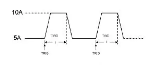
- Pulse mode: in this mode, after the test is started, the load will switch from level A to level B every time it receives a trigger signal, and then switch back to level A after maintaining level B pulse width.

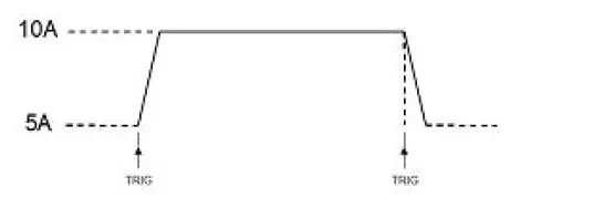
- Trigger mode: in this mode, after the test is started, the load will switch between level A and level B every time it receives a trigger signal. Setting the pulse width will not work in this mode.

- ET5410、ET5411 Single-Channel Programmable DC Electronic Load User Manual

List Test
The list test function makes it easy to test the working conditions of the source to be measured under different loading statuses, which is conducive to the automated testing of the production line. Preset the steps of the list test, and then edit the test steps and test parameters of the source to be measured into a list and complete a series of tests in sequence. Specific parameter settings include a number of steps, step mode, repeat switch, and load mode, load size, delay time, compare switch, maximum value and minimum value of each step.
Press “Shift” + [◀ ] (Menu) on the list test main interface to enter the list menu interface. Rotate the knob to select the corresponding option, and press [Enter] to enter the corresponding sub-menu.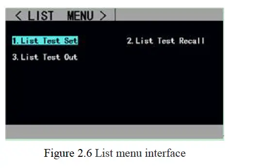
The setting interface and testing interface are shown in figure 2.6.1 and 2.6.2 respectively, and the test outcome interface at the end of the test is shown in figure 2.6.3.
Operating instructions for the list test setting interface: 1. Select the operation option by rotating the knob; 2. Press the direction keys to switch to the edit status before any parameter can be edited. Press the direction key to select the previous or next page and then press [Enter] to turn the page. Press the direction key to select “save” and then press [Enter] to enter the list test parameters saving interface. 3. In the editing status, press [Enter] to switch set options for non-numeric parameters. 4. As for the setting of numeric parameters in editing status, press [Enter] to enter the edit mode and press the direction keys to select the corresponding number of digits. Rotate the knob to adjust the value and press [Enter] or [Esc] to exit the edit state. 5. Press [Esc] to return to the previous interface.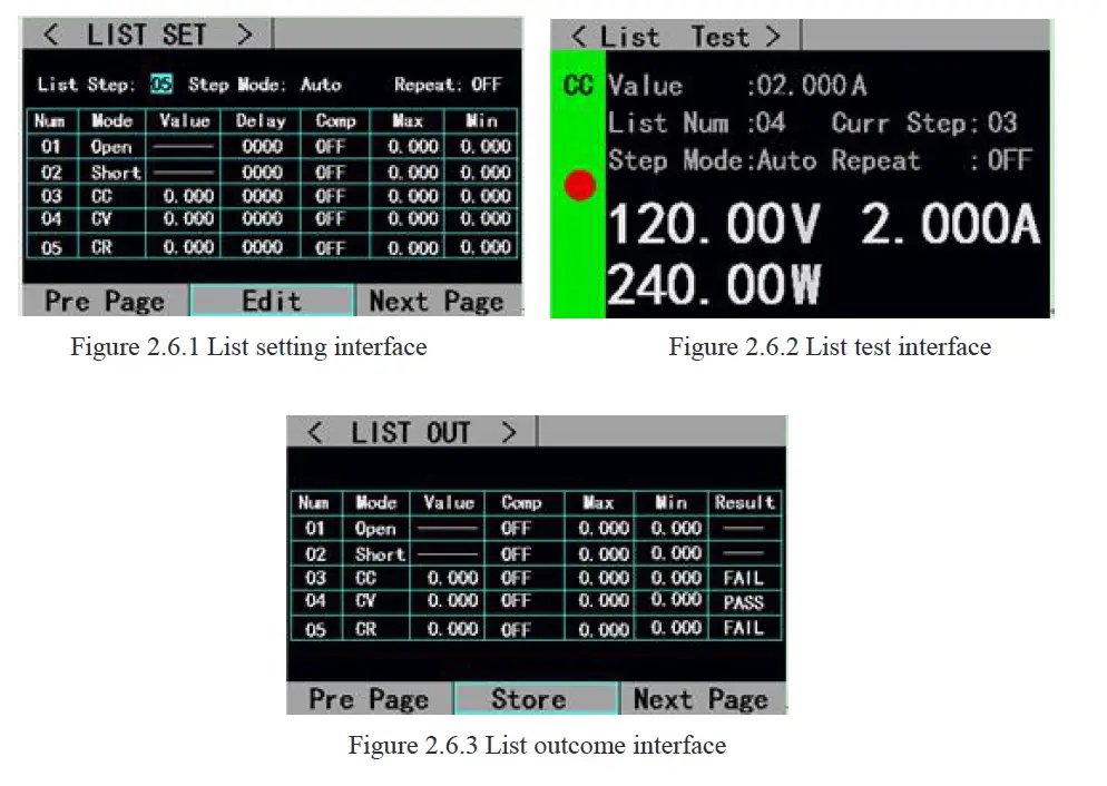
Operating instructions for list test outcome saving interface:1. Select the file by rotating the knob; 2. Press direction keys to switch to the edit state before any file can be edited. Press the direction key to select the previous or next page and then press [Enter] to turn the page. 3. In the editing state, rotate the knob to select the operation of storing, recalling or deleting files, and press [enter] to enter the file rename interface, or to recall or delete the files. 4. Press [Esc] to return to the previous interface;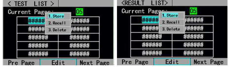
Operating instructions for file rename interface: 1. Press the direction keys to switch to the edit state before any file can be edited. Switch to “store” and press [Enter] to save the file. If it is a null character, an error will be reported. 2. Select the character by rotating the knob in the editing state and press [Enter] to type the character; 3. Press [Esc] to return to the previous interface;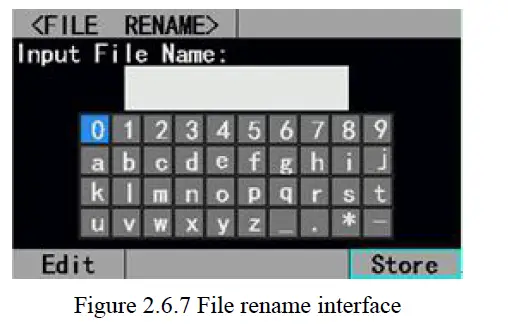
Scan Test
Scan test can be used to detect the continuous working conditions of the source to be measured within a certain range, and makes it easy to capture various critical parameters of the source to be measured, such as protection current, break over voltage and so on. Users can set the scan start value, end value, step value, step delay, threshold type, compare type and other related parameters. After the completion of the scan test, it will show whether the test result is qualified or not.
Operating instructions for parameter setting interface: 1. Press [Shift]+[◀ ](Menu) on the main interface of scan test to enter the scan setting interface; 2. Select the operation option by rotating the knob; 3. Press [Enter] to switch set options for non-numeric parameters. 4. As for the setting of numeric parameters, press [Enter] to enter the edit mode, and press the direction keys to select the corresponding number of digits. Then rotate the knob to adjust the value and press [Enter] to exit the edit mode. 5. Press 【Esc】to return to the previous interface.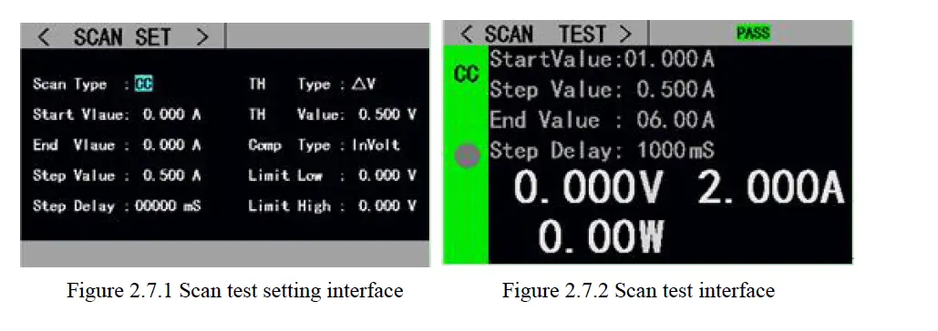
Battery Test
A battery test is commonly used to test the discharge performance of the battery. The electronic load can work with constant current or constant resistance, which makes it easy to measure the discharge capacity of the battery.
Operating instructions for parameter setting interface: 1. Press [Shift]+[◀ ](Menu) on the main interface of battery test to enter the battery setting interface; 2. Select the operation option by rotating the knob; 3. Press [Enter] to switch set options for non-numeric parameters. 4. As for the setting of numeric parameters, press [Enter] to enter the edit mode, and press the direction keys to select the corresponding number of digits. Then rotate the knob to adjust the value and press [Enter] or [Esc] to exit the edit mode. 5. Press【Esc】to return to the previous interface.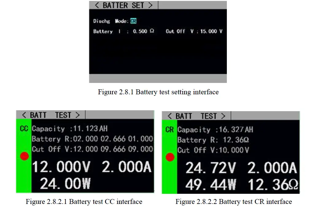
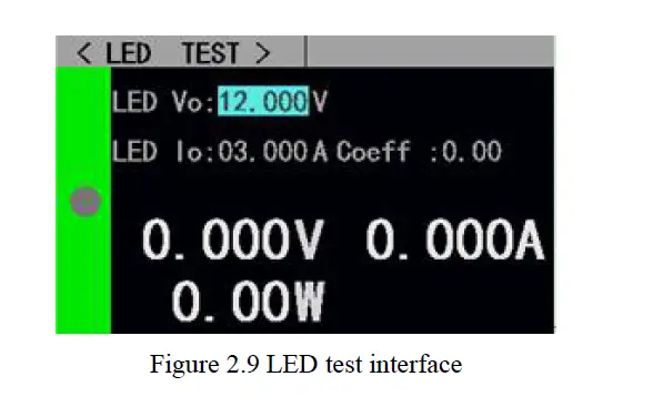
LED Test
CR-LED test can simulate the characteristics of real LED lights. In the traditional CR mode, the forward voltage of diode is increased so that when the input voltage of the load exceeds the forward voltage of the diode, the load will start to work, which can truly reflect the load capacity of the LED drive power.
Operating instructions: 1. Select the operation option by rotating the knob. 2. Parameter settings. Press [Enter] to enter the edit mode and press the direction keys to select the corresponding number of digits. Rotate the knob to adjust the value and press [Enter] or [Esc] to exit the edit mode. 3. Press [On/Off] to turn on or off the mode.
| Name | Content | Description |
| LED Vo: | 0—Vmax | Steady working voltage of LED constant current source with LED lamp |
| LED Io: | 0—Imax | Output current of LED constant current source |
| LED Coeff: | 0.01—1 | The ratio of Rd voltage to the total voltage in the circuit |
According to the following equations (1) and (2), the LED forward voltage and LED impedance can be obtained based on the above parameters. Vf is defined as forward voltage of the diode and Rd as LED impedance.
- Rd = (Vo / Io) 1
- Coeff Vf = Vo * (1 – Coeff) 2

Short Circuit Test
The load can simulate a short circuit at the input end. Under the short circuit test, the actual current consumed by the load short circuit depends on the maximum output of the power supply.
Operating instructions: 1. Select the operation option by rotating the knob. 2. Parameter settings. Press [Enter] to enter the edit mode and press the direction keys to select the corresponding number of digits. Rotate the knob to adjust the value and press [Enter] or [Esc] to exit the edit mode. 3. Press [On/Off] to turn on or off the mode.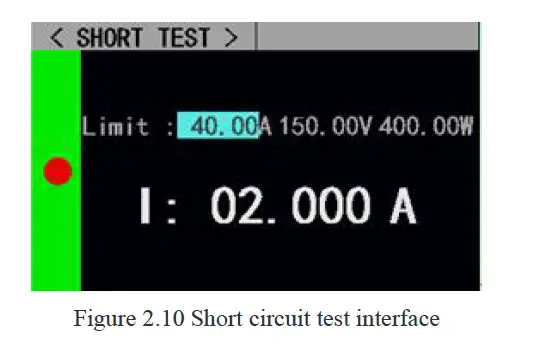
Protection function
The load provides overcurrent, overvoltage, overpower, over-temperature protection, and reverse polarity prompt (the prompt information is subject to the real picture).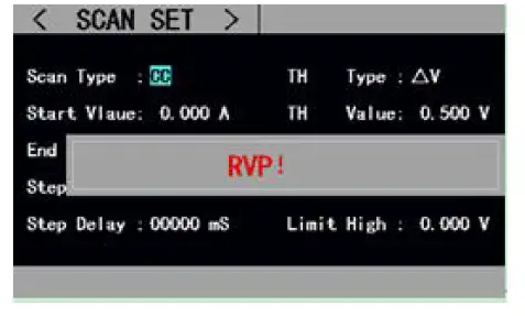
Trigger function
The load has trigger function, which is mainly used in Tran test and list test to trigger the next step. The load supports three trigger modes: 1. Manual (triggered by pressing【Trigger】on the front panel). 2. External (triggered through the back panel trigger port). 3. Bus (triggered by the program control commands of RS-232 or 485 bus interface).
Qualification test
The qualification test is an additional function of the basic measurement modes of CC/CV/CR/CP. When the qualification test is started, it can detect in real-time whether the current test is within the set limit range on the main interface of basic measurement mode and display Pass/Fail. Operating instructions for parameter setting interface: 1. Select the operation option by rotating the knob; 2. Press [Enter] to switch set options for non-numeric parameters. 3. As for the setting of numeric parameters, press [Enter] to enter the edit mode and press the direction keys to select the corresponding number of digits. Rotate the knob to adjust the value and press [Enter] or [Esc] to exit the edit state. 4. Press [Esc] to return to the previous interface.
Key-Lock Function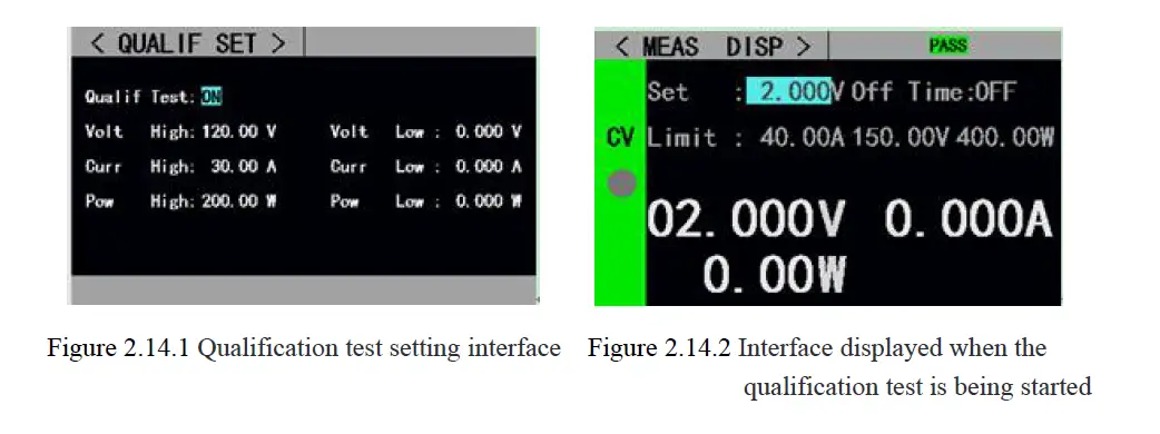
The load also added the lock function to prevent user misoperations. The title bar will display the lock identifier. All the other keys including the knob are locked in the locked state, except the [On/Off], [Enter] and [Local] keys. In addition, in the locked state a lock icon will appear in the icon bar and disappear when unlocking. Long press [Enter] for 3s to switch between “locked” and “unlocked” state.
External Interface
ET54 series is equipped with RS232 (optional) or 485 (optional) and USB two communication interfaces, users can choose any interface to complete the communication with the computer.
USB interface:
After connecting the load and PC via the male-to-male USB cable, serial port software or upper computer can be used to communicate with the load at PC end. The configuration and communication mode are the same as the RS232 interface.
| Interface | Pin | Pin Definition | Description |
| RS232 | 2 | RXD | RS232 interface |
| 3 | TXD | RS232 interface | |
| RS485 | 1 | A | RS485 interface |
| 2 | B | RS485 interface | |
| Common interface | 5/6 | GND | |
| Indication interface | 4 | PASS | Test result level output |
| 7 | NTRI | External trigger input | |
| 8 | FAIL | Test result level output | |
| 9 | RUN | Operating status level output |
Communication interface description: RS-232 or 485 interfaces support SCPI protocol and can be programmed through SCPI commands. When using RS232 or 485 interfaces for data communication, relevant communication parameters should be set at PC end and load end. For example, communication parameters of load can be set on the communication setting interface, as shown in figure. 2.15.2.Indication interface description: For test result output and operating status indication, low-level output is effective and the default output is high level 3.3v. For the external trigger input pin, falling edge is effective, and the interval between two falling edges should be greater than 10mS.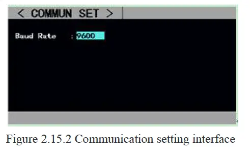
Technical specifications
| Model | ET5410 | ET5411 | |||
| Rated input | Power | 400W | 400W | ||
| Input voltage | 0-150V | 0-500V | |||
| Input current | 0-40A | 0-15A | |||
| CV mode | Range | 0.1~19.999V,0.1~150.00V | 0.1~19.999V,0.1~500.00V | ||
| Resolution | 1mV,10mV | ||||
| Accuracy | ±(0.05%+0.02%FS) | ||||
|
CC mode | Range | 0~3.000A,0~40.00A | 0~3.000A,0~15.00A | ||
| Resolution | 1mA,10mA | ||||
| Accuracy | ±(0.05%+0.05%FS)(0~30A) | ±(0.05%+0.05%FS) | |||
| ±(0.08%+0.1%FS)(30~40A) | |||||
| CR mode | Range | 0.05Ω~1 kΩ,1 kΩ~4.5kΩ | |||
| Resolution | 10mΩ,100mΩ | ||||
| Accuracy | ±(0.1%+0.5%FS) | ||||
| CP mode | Range | 0~400W | 0~400W | ||
| Resolution | 10mW | ||||
| Accuracy | ±(0.1%+0.5%FS) | ||||
| Tran Test | Mode | CC,CV | |||
| T1&T2 | 1ms~60s;Resolution:1ms | ||||
| Accuracy | 0.1%+1ms | ||||
|
Battery Test | Discharge mode | CC,CR | |||
| Maximum discharge capacity | 9999Ah | ||||
| Resolution | 1mA,10mA,10mΩ,100mΩ | ||||
| Range of measurement | |||||
| Voltage read-back value | Range | 0~19.999V,0 ~150.00V | 0~19.999V,0~500.00V | ||
| Resolution | 1mV,10mV | ||||
| Accuracy | ±(0.05%+0.1%FS) | ||||
| Current read-back value | Range | 0~3.000A,0~40.00A | 0~3.000A,0~15.00A | ||
| Resolution | 1mA,10mA | ||||
| Accuracy | ±(0.05%+0.1%FS)(0~30A) | ±(0.05%+0.1%FS) | |||
| ±(0.08%+0.1%FS)(30~40A) | |||||
| Power read-back value | Range | 400W | |||
| Resolution | 10mW | ||||
| Accuracy | ±(0.1%+0.5%FS) | ||||
| Scope of protection | |||||
| Overvoltage protection | >155V overvoltage protection | >510V overvoltage protection | |||
| Overcurrent protection | >42A input cut off | >16A input cut off | |||
| Overpower protection | 420W | ||||
| Over-temperature protection | 85℃ | ||||


