![]() POWER COMMANDER 6
POWER COMMANDER 6
Install guide for PC6-12021
Model coverage: 2015-2016 BMW S1000RR
PARTS LIST
1 POWER COMMANDER 6
1 INSTALLATION GUIDE
1 USB CABLE
2 DYNOJET DECALS
2 POWER COMMANDER DECALS
2 VELCRO STRIPS
1 ALCOHOL SWAB
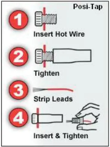
2 POSI-TAPS
PLEASE READ ALL DIRECTIONS BEFORE STARTING INSTALLATION.
THE IGNITION MUST BE TURNED OFF BEFORE INSTALLATION.
INPUT ACCESSORY GUIDE
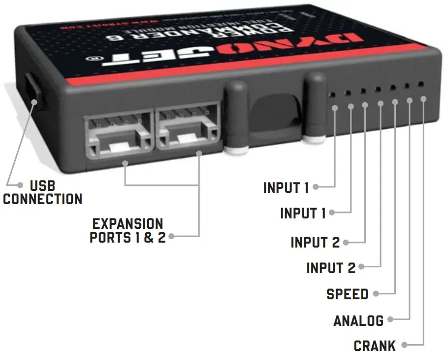
OPTIONAL ACCESSORY INPUTS
| Map | (Input 1 or 2) The PC6 has the ability to hold 2 different base maps. You can switch on the fl y between these two base maps when you hook up a switch to the MAP inputs. You can use any open/close type switch. The polarity of the wires is not important. |
| Shifter | (Input 1 or 2) Used for clutch-less full-throttle upshifts. Insert the wires from the Dynojet quick shifter into either Input 1 or Input 2. The polarity of the wires is not important. Set to Input 2 by default. |
| Speed | If your application has a speed sensor then you can tap into the signal side of the sensor and run a wire into this input. This will allow you to calculate gear position in the Control Center Software. Once gear position is setup you can alter your map based on gear position and setup gear-dependent kill times when using a quick-shifter… |
| Analog | This input is for a 0-5v signal such as engine temp, boost, etc. Once this input is established you can alter your fuel curve based on this input in the Power Core software. |
| Launch | You can connect a wire to either Input 1 or Input 2 and then the other end to a switch. This switch when engaged (continuity) will only allow the RPM to be raised to a certain limit (set in the software). When released, you will have full RPM. |
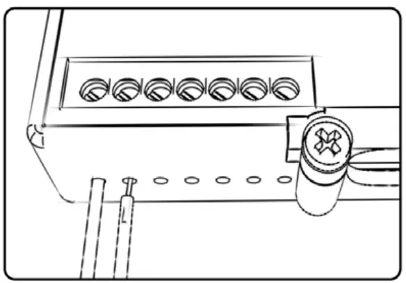
WIRE CONNECTIONS
To input wires into the PC6 first remove the rubber plug on the backside of the unit and loosen the screw for the corresponding input. Using a 22-24 gauge wire, strip about 10mm from its end. Push the wire into the hole of the PC6 until it stops and then tightens the screw. Make sure to reinstall the rubber plug.
NOTE: If you tin the wires with solder it will make inserting them easier.
INSTALLING THE POWER COMMANDER 6
- Remove the seat.
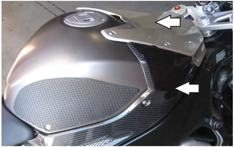
- Remove the fuel tank covers.
- Remove the fuel tank or prop it up out of the way.
- Remove the left and right side fairings.

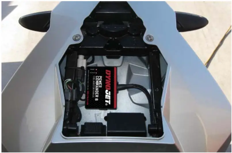
- Using the supplied Velcro, secure the PC6 in the tail section.
Make sure to use the supplied alcohol swab to clean both surfaces before attaching the Velcro.
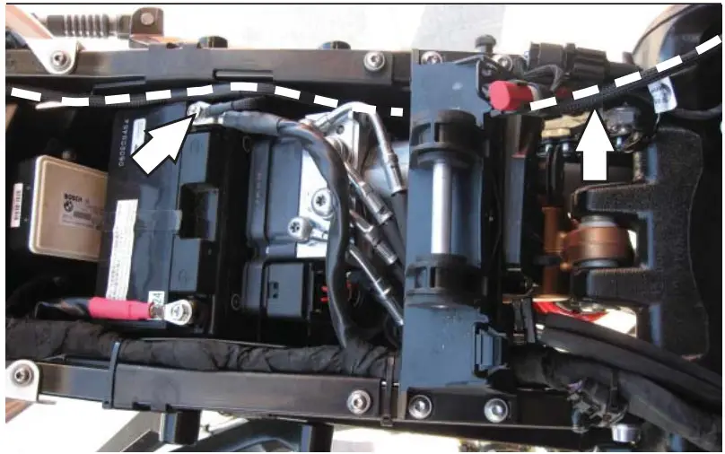
- Route the PC6 harness down the left side of the bike.
Route the harness underneath the fuel tank bracket and go towards the throttle bodies. - Attach the ground wire from the PC6 with the small ring lug to the negative (-) terminal on the battery.

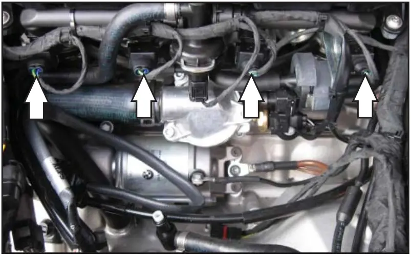
- Unplug the stock wiring harness from each fuel injector.

- Plug the PC6 harness in line with the stock wiring harness and each fuel injector.
PC6 harness:
Orange – cylinder #1 (left)
Yellow – cylinder #2
Green – cylinder #3
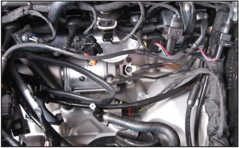
Blue – cylinder #4 (right) - Locate the Throttle Position Sensor (TPS) connector from the throttle bodies on the left, inside of the frame.

- Using the supplied postal, attach the grey wire from the PC6 to the stock white/grey wire on the TPS connector.
It is recommended to use dielectric grease on these connections.
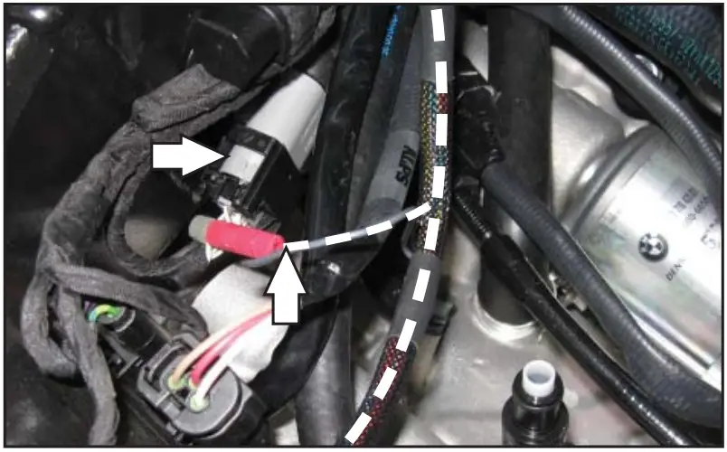
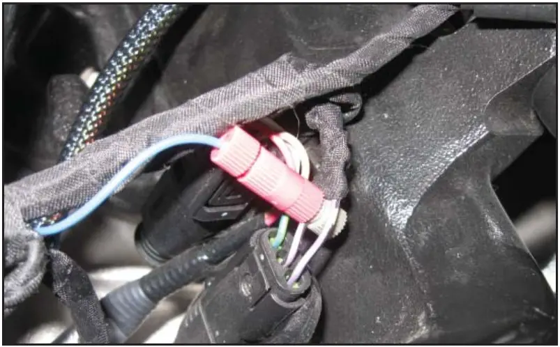
- Using the supplied postal, attach the blue wire from the PC6 to the stock purple/black wire of the gear position sensor connector.
This connector is located under the fuel tank to the left, rear of the frame.
There are two purple/black wires on this connector; use the one in the middle.
- Reinstall the fuel tank, bodywork, and seat.

To see a video demonstration of this install, visit www.dynojet.com or our YouTube channel DynojetResearch.
Download the latest map files from our website at dynojet.com/tunes.
PUSH THE LIMIT
2015-2016 BMW S1000RR
2191 MENDENHALL DRIVE, NORTH LAS VEGAS, NV
89081 – 800-992-4993
DYNOJET.COM
© 2015-2022 DYNOJET RESEARCH
ALL RIGHTS RESERVED
IPC6-12021.01


