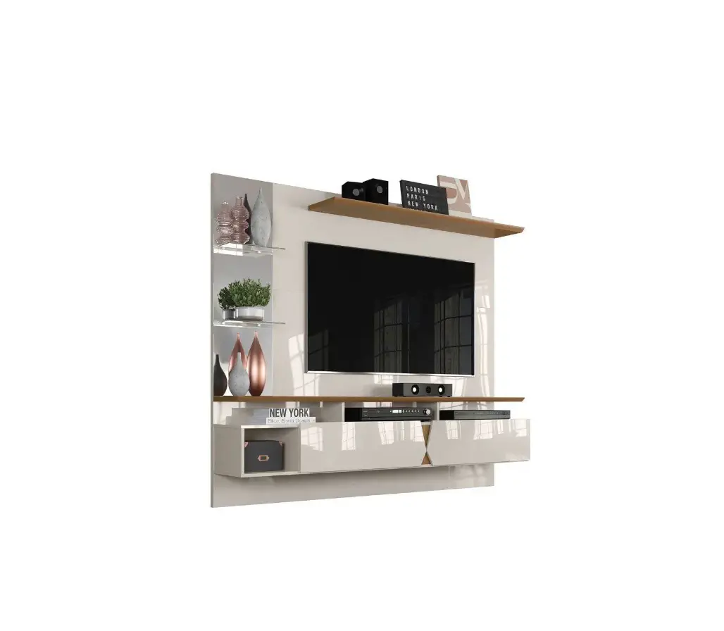
Lukaliam Intense TV Panel
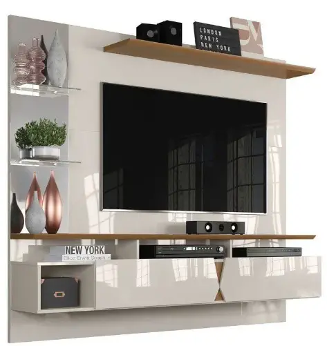
IDENTIFICATION OF THE PARTS
Nº | MEASURE | NAME |
| 01 | 1830×299 | Base |
02 | 297×209 | Left Side |
| 03 | 297×209 | Left Partition |
04 | 280×209 | Right Partition |
| 05 | 297×209 | Right side |
06 | 1830×299 | Intermediate Top |
| 07 | 189×108 | Top Right Support |
08 | 189×108 | Top Left Support |
| 09 | 1828×267 | Upper Top |
10 | 1832×542 | Lower Panel |
| 11 | 1832×542 | Intermediate Panel |
12 | 1832×542 | Upper Panel |
| 13 | 1300×177 | Upper Shelf |
14 | 209×102 | Door Stop |
15 | 759×240 | Left Door |
| 16 | 759×240 | Right Door |
17 | 480×60 | Bottom Frame Detail |
| 18 | 1140×60 | Upper Frame Detail |
19 | 676×65 | Fixed Wedge |
20 | 676×45 | Mounting Panel |
| 21 | 951×30 | Template |
22 | 200×40 | Panel Support |
Warranty Certificate
Lukaliam Indústria e Comércio de Móveis Ltda., always seeking the tranquility and confidence of its customers on the products dedicated to them presents the appropriate warranty certification. In accordance with the product warranty given by this certificate of Lukaliam Mó veis Ltda., the consumer/client must pay caution as follo ws:
- Always ensure normal and proper use of the product, avoiding misuse, excessive exposure to sunlight and heat, as this can cause a change in the original color of the pr oduct;
- We remind you that damages caused on the handling and transportation of pr oducts are not valid for this certificate, and, we suggest for transportation the use of specialized professionals.
- The Warranty is limited solely and exclusively to the furnitur e, not covering the products added to it, such as glasses, wires, hardware, and other accessories that are not manufactur ed by Lukaliam ndústria e Comércio de Móveis ltda.
Warranty deadlines
90 days from the invoice issue date, both for easy to find defects, and for manufacturing defects, except following the conditions of normal use of the product, and other considerations of this certificate, counted from the invoice issue date.
Cleaning, assembly and care instructions
Regarding the cleaning of the product, we recommend the use of only cloth lightly moistened with water; The client/consumer must certify and monitor the moment of assembly, signing a satisfaction term, to avoid further complications in the assembly, which is responsibility of the client/consumer, thus rendering this warranty term inapplicable, as well as any kind of cutouts in the furnitur e.
The company Lukaliam Indústria e Comercio de Moveis Ltda is not responsible for problems originated by the misuse of the products, exposure to bad weather, and also b y the action of various pests, termites, and also, in the improper storage of the product in places that ar e not regularly sprayed.
Final remarks
This warranty certificate must be exercised within the time limits indicated in this act by the resellers stores of the products of the company Lukaliam Indústria e Comércio de Móveis Ltda. Especially the one that the product was purchased, upon presentation of the invoice, and this certificate. We highlight that technical assistance will not be granted if the misuse of the pr oduct is detected.
QUANTITY OF ACCESSORIES
Screws in real size | |||
A | 28 | 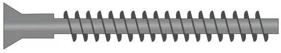 | FLAT POINT SCREW 5X50 |
B | 02 | 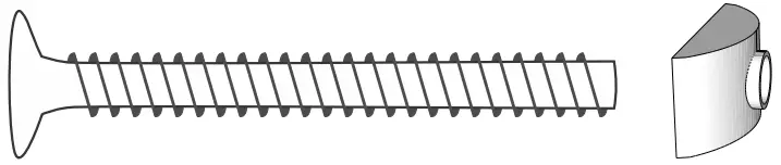 | SCREW W/ ELLIPTICAL NUT |
C | 08 | POINT SCREW 6X80 | |
D | 31 |  | FLAT HEAD SCREW 3,5X25 |
E | 06 |  | FLANGE HEAD SCREW 3,5X12 |
F | 32 | 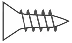 | FLAT HEAD SCREW 3,5X12 |
G | 08 |  | CAM LOCK 12mm |
H | 35 | 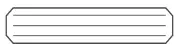 | WOODEN DOWEL PIN |
I | 08 |  | ANCHER 10 |
G | 04 | 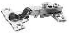 | HINGE |
K | 02 |  | CABLE GROMMET |
L | 04 |  | GLASS SHELF SUPPORT |
M | 02 |  | METAL MENDING PLATE |
N | 03 |  | ANGLE BRACKET |
O | 02 | 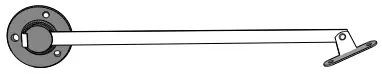 | ARTICULATOR |
FOR A PERFECT ASSEMBLY OF YOUR PRODUCT, READ CAREFULLY THE INSTRUCTIONS OF EACH STEP.
ATTENTION: Fix the TV support with through bolt, washer and nut.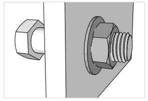
The Company is not responsible for the incorrect fixing of the TV support to the panel.
*Use the packaging to cover the floor and assemble the furniture on it.
Assembly Instructions
Step 1
08- WOODEN DOWEL PIN- H
08- FLAT POINT SCREW- A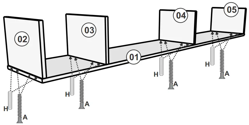
Fix the parts 02, 03, 04 and 05 on part 01 with Wooden Dowel Pin (H) and Flat Point Screw (A).
Step 2
02- WOODEN DOWEL PIN- H
04- FLAT POINT SCREW- A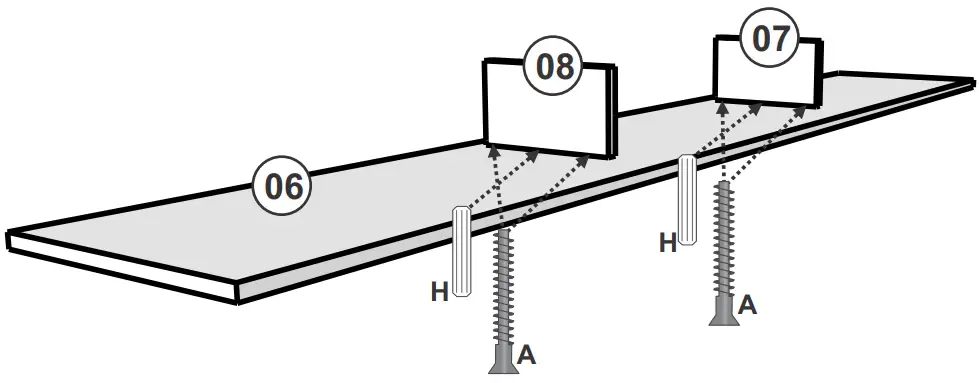
Fix the parts 07 and 08 on part 06 with Wooden Dowel Pin (H) and Flat Point Screw (A).
Step 3
06 – CAM LOCK- G
08 – WOODEN DOWEL PIN- H|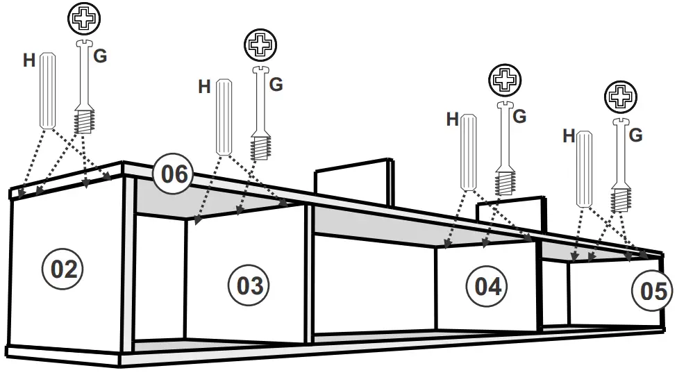
Fix the part 06 on parts 02, 03, 04 and 05 with Cam Lock (G) and Wooden Dowel Pin (H).
Step 4
02 – CAM LOCK – G
04 – WOODEN DOWEL PIN – H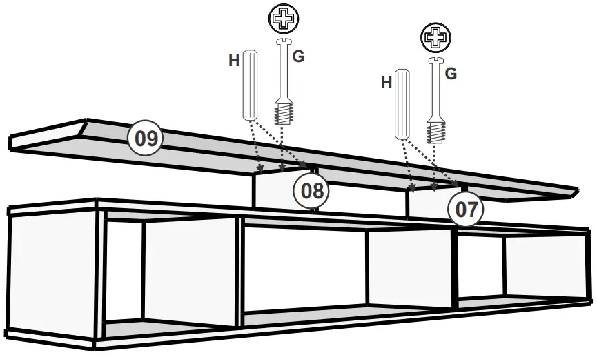
Fix the part 09 on parts 07 and 08 with Cam Lock (G) and Wooden Dowel Pin (H).
Step 5
06 – WOODEN DOWEL PIN- H
13 – FLAT POINT SCREW – A
02 – SCREW W/ ELLIPTICAL NUT – B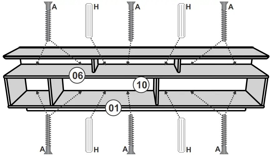
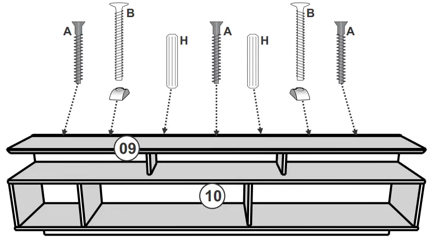
Fix the part 10 on parts 01 and 06 with Wooden Dowel Pin (H) and Flat Point Screw (A).
Fix the part 10 on part 09 with Wooden Dowel Pin (H), Flat Point Screw (A) and Screw w/ Nut (B).
Step 6
09 – FLAT HEAD SCREW – D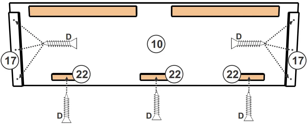
Fix the parts 17 with Flat Head Screw (D) facing the sides on part 10.
Fix the parts 22 with Flat Head Screw (D).
Step 7
04 – POINT SCREW – C
04 – ANCHER – I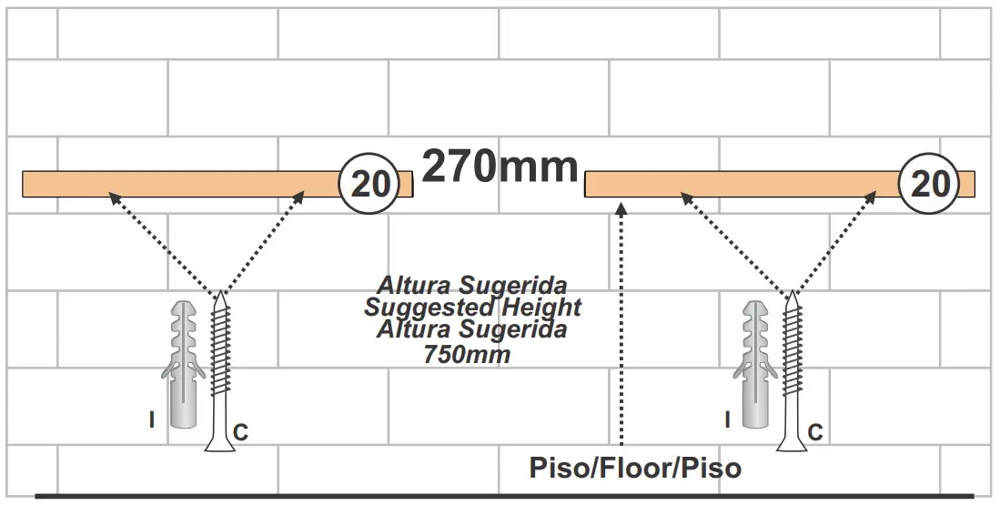
Fix the parts 20 on the wall with Point Screw (C) and Ancher (I).
Leave a distance of 270mm between the parts 20.
Step 8
04 – POINT SCREW – C
04 – ANCHER – I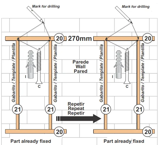
Lean the parts 21 on the parts 20 already fixed, lean the new parts 20 on the top of templates and mark the wall.
Fix the parts 20 on the wall with Point Screw (C) and Ancher (I).
Step 9
03 FLAT POINT SCREW – A
02 – WOODEN DOWEL PIN – H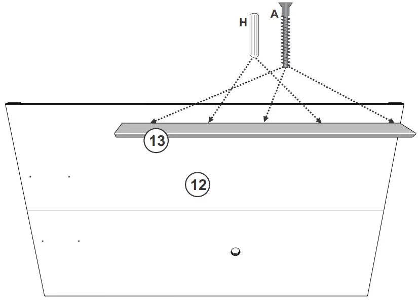
Step 10
12 – FLAT HEAD SCREW – D
08 – FLAT HEAD SCREW – F
02 – METAL MENDING PLATE – M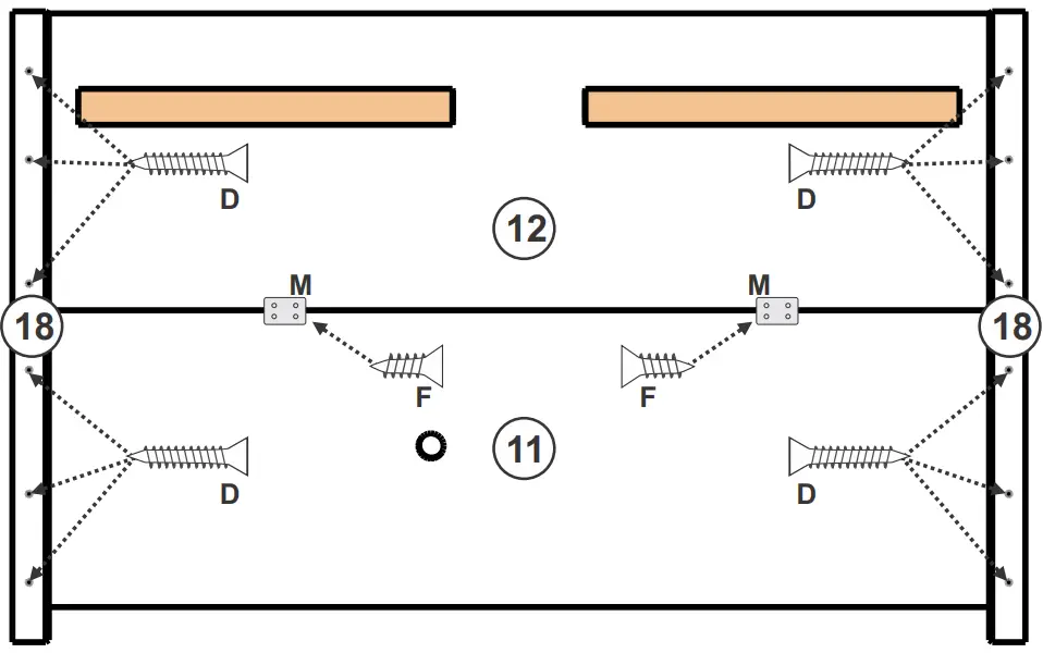
Fix the Metal Mending Plate (M) with Flat Head Screw (F) to fix the panels 11 and 12.
Fix the parts 18 with Flat Head Screw (D) facing the sides on the panels 11 and 12.
Step 11
12 – FLAT HEAD SCREW – D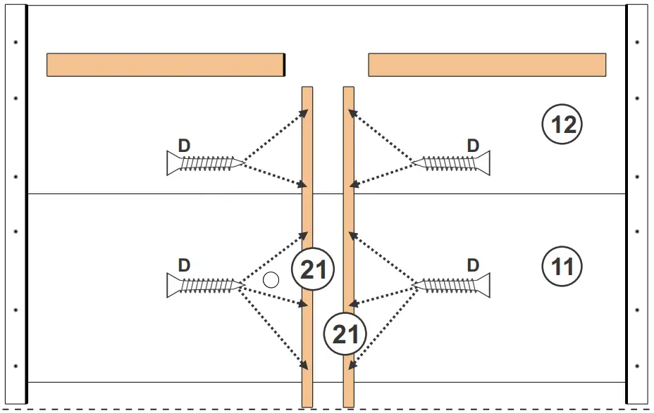
Fix facing the frames
Fix the parts 21 (that were used as templates) on the panels 11 and 12 with Flat Head Screw (D).
Step 12
06 – FLANGE HEAD SCREW – E
03 – ANGLE BRACKET – N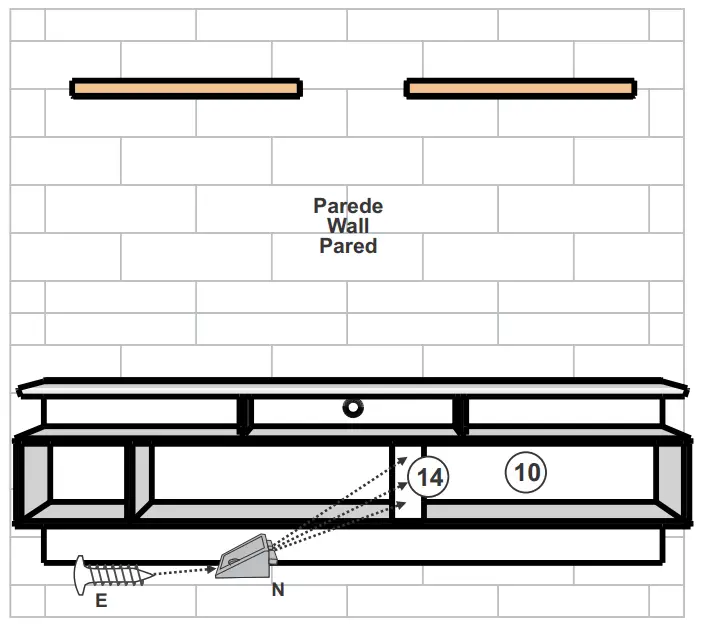
Fix the part 14 on part 04 with Angle Brackets (N) and Flange Head Screw (E).
Hang the part 10 on the part 20 fixed on the wall.
Step 13
04 – FLAT HEAD SCREW – F
04 – FLAT HEAD SCREW – F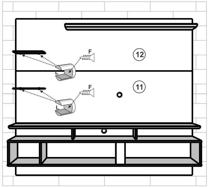
Hang the parts 11 and 12 on the part 20 fixed on the wall.
Fix the Glass Shelf Support (L) with Flat Head Screw (F).
Step 14
26 – FLAT HEAD SCREW – F
04 – HINGE – J
02 – ARTICULATOR – O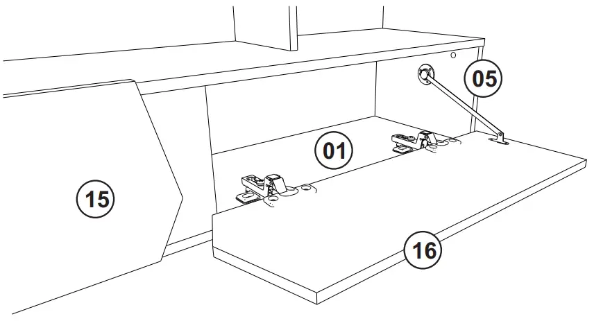
Fix the Doors 15 and 15 on part 01 with Hinge (J) and Flat Head Screw (F).
Fix the Door 16 on part 05 with Articulator (O) and Flat Head Screw (F).
Fix the Door 15 on part 02 with Articulator (O) and Flat Head Screw (F).
Step 15
03 – MIRROR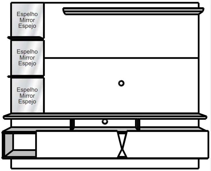
Fix the Mirrors with Double Sided Tape.


