![]()
ViVOpay VP3350
Integration Manual 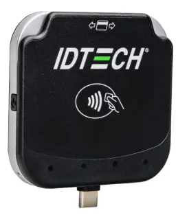
80178501-001 Rev. D
8 March 2023
ID TECH
10721 Walker Street, Cypress, CA 90630-4720
Tel: (714) 761-6368 Fax (714) 761-8880
www.idtechproducts.com
ID TECH VP3350 Integration Manual
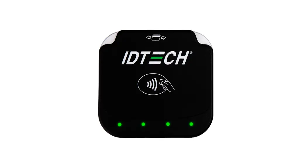
ViVOpay VP3350 3 In 1 Card Reader
Copyright © 2023 ID TECH. All rights reserved.
ID TECH
10721 Walker Street
Cypress, CA 90630 USA
This document, as well as the software and hardware described in it, is furnished under license and may be used or copied online in accordance with the terms of such license. The content of this document is furnished for information use only, is subject to change without notice, and should not be construed as a commitment by ID TECH. While every effort has been made to ensure the accuracy of the information provided, ID TECH assumes no responsibility or liability for any unintentional errors or inaccuracies that may appear in this document. Except as permitted by such license, no part of this publication may be reproduced or transmitted by electronic, mechanical, recording, or otherwise, or translated into any language form without the express written consent of ID TECH.
ID TECH and ViVOpay are trademarks or registered trademarks of ID TECH.
Warranty Disclaimer
The services and hardware are provided “as is” and “as-available” and the use of the services and hardware are at its own risk. ID TECH does not make, and hereby disclaims, any and all other express or implied warranties, including, but not limited to, warranties of merchantability, fitness for a particular purpose, title, and any warranties arising from a course of dealing, usage, or trade practice. ID TECH does not warrant that the services or hardware will be uninterrupted, error-free, or completely secure.
FCC warning statement
This device complies with Part 15 of the FCC Rules. Operation is subject to the following two conditions: (1) this device may not cause harmful interference, and (2) this device must accept any interference received, including interference that may cause undesired operation.
The user manual for an intentional or unintentional radiator shall caution the user that changes or modifications not expressly approved by the party responsible for compliance could void the user’s authority to operate the equipment.
Note: The grantee is not responsible for any changes or modifications not expressly approved by the party responsible for compliance. Such modifications could void the user’s authority to operate the equipment.
Note: This equipment has been tested and found to comply with the limits for a Class B digital device, pursuant to part 15 of the FCC Rules. These limits are designed to provide reasonable protection against harmful interference in a residential installation. This equipment generates uses and can radiate radio frequency energy and, if not installed and used in accordance with the instructions, may cause harmful interference to radio communications. However, there is no guarantee that interference will not occur in a particular installation. If this equipment does cause harmful interference to radio or television reception, which can be determined by turning the equipment off and on, the user is encouraged to try to correct the interference by one or more of the following measures:
- Increase the separation between the equipment and the receiver.
- Connect the equipment into an outlet on a circuit different from that to which the receiver is connected.
- Consult the dealer or an experienced radio/TV technician for help.
This device complies with FCC RF radiation exposure limits set forth for an uncontrolled environment.
The antenna(s) used for this transmitter must not be co-located or operating in conjunction with any other antenna or transmitter and must be installed to provide a separation distance of at least 20cm from all persons.
Cautions and Warnings
| Caution: Danger of Explosion if battery is incorrectly charged. Use only standard USB 5V power source. Device contains a lithium battery. Approved temperature range for storage: -20℃ to +60℃. Disposal: Contact your local recycling center. | |
| Warning: Avoid close proximity to radio transmitters, which may reduce the capabilities of the reader. |
Internal Rechargeable Battery Warning
Danger: Do not attempt to replace the internal rechargeable lithium-ion battery. Replacing the original battery with an incompatible type may result in an increased risk of personal injury or property damage due to explosion, excessive heat, or other risks. Do not attempt to disassemble or modify the battery pack. Attempting to do so can cause a harmful explosion or battery fluid leakage.
When disposing of the battery, comply with all relevant local ordinances or regulations. Do not dispose of the battery pack in municipal waste. Dispose used batteries according to the instructions. The battery pack contains a small amount of harmful substances.
To avoid injury:
- Keep the battery pack away from open flames or other heat sources.
- Do not expose the batter pack to water, rain, or other corrosive liquids.
- Do not leave the battery in an environment with extremely low air pressure. It may result in an explosion or the leakage of flammable liquid or gas from the battery.
To extend battery life, we recommend charging the battery to at least 30% to 50% capacity each time and recharging it every three months to prevent over discharge.
Note that the VP3350 is a PCI SRED certified device; any attempt to replace the internal Lithium-Ion battery will result in a device tamper, rending the unit inoperable.
Revision History
| Date | Rev | Changes | By |
| 12/08/2022 | A | Initial release. | CB |
| 02/06/2023 | B | Updated LED and Sound State Indicators table and footnote. | CB |
| 02/16/2023 | C | Updated mounting guidelines and diagrams. | CB |
| 03/08/2023 | D | Tag 9F33: Updated byte 2 bit 5 (feature not supported). | CB |
Introduction
The ViVOpay VP3350 is ID TECH’s latest PCI 6.X SRED-certified and non-SRED mobile reader. The VP3350 supports Magstripe, EMV contact, and contactless transactions using either USB-C, Lighting, and/or Bluetooth connections.
The VP3350’s compact form factor and Bluetooth interface make it ideal for mobile applications where smart card reading is required as well as incorporated into a case or stand associated with a countertop POS terminal. As a mobile reader, VP3350 works in conjunction with Android as well as iOS phones and tablets via BLE. The VP3350 is designed to be compatible with a wide range of third-party payment applications, and the ID TECH Universal SDK (described further below) is available for developing applications that communicate with VP3350.
Contact your acquirer, gateway, or POS partner for instructions on setting up and pairing the VP3350 to a compatible payment application and associated host device.
Major VP3350 Features
- Communicates via Bluetooth BLE (Bluetooth Low Energy)
- Bluetooth communication supports iOS and Android platforms
- Communicates to iPhone host devices via Lightning connector
- Communicates to iPad or Android host devices via USB-C male connector
- USB-C 2.0 female connector supports battery charging or communication with Android or Windows host systems
- Rechargeable battery, no external power necessary
- Supports pass-through charging
- ICC: EMV Level 1 Contact certified and integrated ID TECH’s EMV L2 Gen 3 Common Contact kernel
- Front-facing contactless transaction support via Near Field Communication (NFC) Magstripe reading
- LED status indicator
- Audio feedback
- Field-upgradable firmware
- Low power consumption when reader is in standby mode
- Compact and ergonomic design to integrate with a variety of mobile devices
- Supports Triple DES, AES128, and TransArmor with DUKPT key management
- Supports 20 contact and 8 contactless AIDs, for a total of 28 AIDs
2.1. Contactless NFC Features and Brand Certifications
- ISO 14443 Type A&B
- ISO 18092 (P2P)
- MasterCard® MChip (Formerly PayPass)
- Discover® DPAS
- American Express® ExpressPay
- Interac
- Interac Transit
- MIFARE – native support
- Apple Pay
- Apple VAS
- Samsung Pay NFC
- Android Pay
- Google Pay / Softcard Smart Tap 2.1
2.2. Other Agency Approvals and Compliances
- CE (EN55032/EN55035, Class- B)
- FCC (Part 15, Class-B)
- RoHS (DIRECTIVE 2015/863/EU)
- UL
- REACH
- EMV Contact L1&L2
- EMV Contactless L1 and majority of Contactless 2
- TQM
- PCI PTS 6.X SRED
2.3. Operation and Storage: Environmental Limits
| Item | Specification | Note |
| Operating Temperature | 0 °C to 55 °C or 32°F to 131°F | Non-condensing. Product operation temperature is limited to this range due to constraints of the Li-Battery specification. |
| Storage Temperature | -20 °C to 60 °C or -4°F to 140°F | Non-condensing. Product storage temperature is limited to this range due to constraints of the Li-Battery specification. |
| Operating Humidity | Up to 95% | Non-condensing. |
| Storage Humidity | Up to 95% | Non-condensing. |
2.4. Power Consumption
- Minimum 800 MSR transaction per charge (with 30 second interval)
- Minimum 500 contact transactions per charge (with 30 second interval)
- Minimum 400 contactless transactions per charge (with 30 second interval)
- Minimum 200 contactless + 200 contact + 100 MSR transactions per charge (with 30 second interval)
Maximum power draw: 500mA for battery charging when input power is over 1A.
2.5. 24-Hour Device Reboot
Per PCI Requirements, this device reboots every 24 hours. Please contact your device integrator if you need to check the reboot time for your unit.
VP3350 Connectors and Interfaces
The VP3350 is designed to work Windows, Android, and iOS via a physical USB-C, Lightning, and Bluetooth communication.
- USB-C communicates with popular Android mobile phones and tablets.
- Lightning connectors communicate with popular mobile iOS devices.
- Bluetooth connection supports both Android and iOS.
- USB-C allows communication to an Android, iOS, or Windows host or allows for passthrough charging to the host device. When communicating over USB, the VP3350’s default emulation mode is USB HID; the reader can also emulate a USB HID-KB interface 2 .
Bluetooth Pairing Instructions
In addition to the following instructions, see the section on iOS Connectivity for more information on using an iPad or iPhone in conjunction with the VP3350.
- Enable the Bluetooth device search function on the host device (smart phone or tablet).
- Make sure the VP3350 is charged or connected to a power source via USB. o When connected to a power source, the VP3350 automatically activates Bluetooth.
- When not connected to a power source, press the VP3350’s power button to automatically activate Bluetooth.
- Find a Bluetooth device named IDTECH-VP3350-XXXXX on the host smart phone or tablet and select Pair.
- Enter the password for pairing. The default password is 123456.
- Follow the payment transaction instructions provided by a compatible payment application maker to complete a transaction.
The VP3350 will remain connected via Bluetooth to the host device indefinitely when powered via the USB cable. If the unit is operating on battery power, it will go to sleep after 20 seconds of idling to extend battery life. To perform a transaction again, press the power button to reestablish the Bluetooth connection. When connecting to an iOS device, please install a compatible payment application and follow the instructions provided by that application’s maker. See iOS Connectivity: BLE and VP3350 below for more information.
4.1. Battery Charging Instructions
VP3350 Lighting and Bluetooth readers are powered by a lithium-ion polymer battery and are delivered in a partially charged state. Be sure to fully charge the VP3350 before using it for the first time. Allow two to three hours for the initial charge.
Use a standard USB to USB-C cable to charge the unit. An LED battery indicator displays the current battery charging status 3
Warning: Do not use “fast chargers” with VP3350 readers. Only use a standard USB to USB-C cable.
4.2. Tamper and Failed Self-Check Indicators
The VP3350 displays the following indicators when it has been tampered or has any of the other following internal issues, such as an expired certificate, missing key, or similar fault discovered during a self-check. 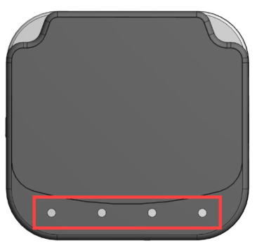
| Indicator | Tampered Status | Other Issue Status |
| Front Four LEDs | All LEDs blink red | All LEDs blink red |
| Buzzer | Alarm tone | Alarm tone |
4.3. VP3350 LED and Sound State Indicators
The VP3350 uses the following LEDs and sounds to indicate various statuses, including power management, Bluetooth, transactions, and security.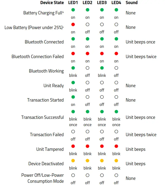
4 Use the Get Battery Level (F0-02) command to retrieve battery level. When charging, the reader displays three greed LEDs to indicate 75% charge, two green LEDs to indicate 50% charge, and one red LED to indicate a charge under 25%.
4.4. iOS Connectivity: BLE and VP3350
The VP3350 uses Bluetooth 5.0, also known as Bluetooth BLE (Bluetooth Low Energy). Unlike previous versions of Bluetooth, BLE does not require users to first pair their devices through the Bluetooth Settings in Apple iOS. If a payment application provider has enabled BLE scanning in their application, Apple iOS scans and locates all BLE devices in range to automatically connect with the VP3350.
It is critical to note that if the VP3350 is paired via the iOS Settings page, it will display as a connected device but not function with a payment app.
Unlike other operating systems that can detect or specify a BLE device by its MAC address, Apple does NOT allow users to specify a BLE device by MAC address for security reasons. Instead, after a device is selected by its “friendly” name (see the next paragraph), the Apple iOS calculates a unique identifier to allow any that device to make further connections directly.
The VP3350 has a default friendly name of IDTECH-VP3350-XXXXX. This is the default name the ID TECH Universal SDK uses to connect to the first VP3350 it encounters if no other friendly name is set in the SDK, or when the iOS-generated device identifier is not provided. See links given near the end of this document for information about the Universal SDK.
Note: The Universal SDK is primarily of interest to developers. If an application provider or POS software partner has already provided software to use with the VP3350, you do not need to obtain the SDK.
ID TECH Universal SDK
By virtue of its EMV L2 kernel, VP3350 is designed to be compatible with a wide range of thirdparty payment applications. ID TECH offers a Universal SDK (available for iOS, Android, or Windows) to enable rapid application development using VP3350 as the target device.
The languages supported include Objective C (on iOS), Java (on Android), and C# (on Windows). The Universal SDK includes rich, powerful libraries that make sending
commands to the VP3350 comparatively easy while greatly facilitating debugging and event handling. To obtain the Universal SDK free of charge, visit ID TECH’s VP3350 product page and select the version of the SDK that applies to your desired host platform (Android, iOS, Linux, MacOS, or Windows). Normally, development of applications that take advantage of VP3350’s capabilities can be done in a high-level language like C# or Java (using convenience objects and data structures defined in the Universal SDK), obviating the need to send byte commands directly. Nevertheless, it is possible to communicate with the device at a low level if necessary. For a command reference for VP3350, request the NEO Interface Developers Guide (IDG), P/N 80139403-001. This document includes not only low level (firmware) commands but error codes, response codes, and information on various default settings.
5.1. Updating VP3350 Firmware
ID TECH strongly recommends updating firmware via the Universal SDK. Consult the Universal SDK Guide for your desired platform (included in the ZIP file downloaded from the VP3350 product page) for integration details.
Note: Firmware downloads must be done via a USB-C cable for PC, a male USB-C cable for mobile Android devices, or a Lightning cable for iOS devices; VP3350 readers do not support firmware over Bluetooth.
Universal SDK Demo App
The Universal SDK comes with a rich, fully featured demo app that allows users to run the VP3350 in USB mode. Visit the VP3350 product page to download the Universal SDK Demo app as a standalone executable, separate from the SDK; the full SDK is not required to use the demo. Be sure to check out the Universal Demo QuickStart Guide for more detailed instructions about using the Universal SDK Demo app.
6.1. Using the Demo Application
Follow the steps below to run the Universal SDK Demo app on Windows:
- Plug the VP3350 into the host device with a USB-C cable (not included).
- Double-click the UniversalSDKDemo.exe file and allow a few seconds for the main window to appear (see illustration below).
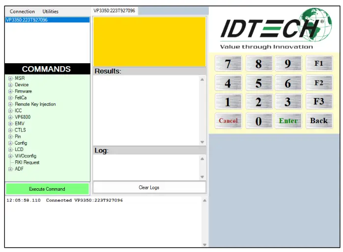
The Universal SDK Demo app displays VP3350’s available commands in a command tree, as shown above. Single-click on a command to populate the center panel of the window with optional settings relevant to the command (for example, “Amount” and “Start EMV Additional Tags” above). In some cases, text fields appear, allowing users to enter custom values.
To execute a command, double-click it in the command tree (or use the Execute Command button at the bottom of the window). The command executes in real time and a data trace appears automatically in the center and/or right-hand panels. Use the Clear Logs button to clear both panels.
VP3350 Low-Level Commands
The following are commonly-used commands for the VP3350. For a full list of available commands, contact your ID TECH representative for the NEO 2 Interface Developer’s Guide.
7.1. Activate Transaction Command (02-40)
The Activate Transaction command begins a contactless EMV or contactless MagStripe Card transaction.
Note: While an Activate command is in progress, readers only accepts a Cancel or Stop command. Do not send other commands until Activate Transaction has completed, because the reader will interpret these as a Cancel Transaction command.
To control the behavior, use the DFEF37 and DFEF3C tags:
| Tag | Length | Description | Example |
| DF EF 37 | 01 | Define the type of interface to be activated with 02-40. Interface selection: · Bit 0: MSR · Bit 1: Contactless · Bit 2: Contact | DF EF 37 01 07 07 = 0000 0111 This activates transaction for all 3 interfaces. |
| DF EF 3C | 03 | Fallback support and Timeout value for waiting for the next command (mainly to support EMV workflow). Byte 1: Fallback support · 0x00: not support fallback · 0x01: support fallback Byte 2~3: Timeout for next command (Unit: Sec) (Hex format) · 00 0A = 10s · 01 00 = 256s | DF EF 3C 03 01 00 60 Fallback is supported, and the timeout is set to 96 seconds before the transaction times out. |
Example: 5669564f746563683200024000221e9c01009f02060000000001009f030600000000 0000dfef370107dfef3c0301006018d1
Command Frame
| Byte 0-9 | Byte 10 | Byte 11 | Byte 12 | Byte 13 | Byte 14 … Byte 14+n-1 | Byte 14+n | Byte 15+n |
| Header Tag & Protocol Version | Command | Sub- Command | Data Length (MSB) | Data Length (LSB) | Data | CRC (LSB) | CRC (MSB) |
| ViVOtech2\0 | 02h | 40h | See Data Format below |
Activate Transaction Command Frame Data Format
| Data Item | Length (bytes) | Description |
| Timeout | 1 | Time in seconds that the reader waits for a card to be presented before timing out and returning an Error response. The reader will continue to poll for this amount of time if no card is found. Note that if a card is found, the transaction may not complete within the timeout period. This field must be present in the Activate command. Format: Binary |
| TLV Data | varies | See Activate Command TLVs in the NEO 2 IDG. |
Response Frame
| Byte 0-9 | Byte 10 | Byte 11 | Byte 12 | Byte 13 | Byte 14 … Byte 14+n-1 | Byte 14+n | Byte 15+n |
| Header Tag & Protocol Version | Command | Status Code | Data Length (MSB) | Data Length (LSB) | Data | CRC (MSB) | CRC (LSB) |
| ViVOtech2\0 | 02h | See Status Code Table | See Response Frame Data Format |
Note: The information above omits many command details, particularly TLV information. See the NEO 2 Interface Developer’s Guide (available from your ID TECH representative) for the full Activate Transaction (02-40) description.
7.2. Set CA Public Key (D0-03)
The Set CA Public Key command adds a new key to the reader.
Command Frame
| Byte 0-9 | Byte 10 | Byte 11 | Byte 12 | Byte 13 | Byte 14 – 18 | Byte 19 | Bytes 19-n | Byte n+1 | Byte n+2 |
| Header Tag & Protocol Version | Cmd | Sub Cmd | Length (MSB) | Length (LSB) | RID (5 bytes) | Key Index (1 byte) | Key Data | CRC (LSB) | CRC (MSB) |
| ViVOtech2\0 | D0h | 03h | varies | varies | varies | varies | See below | Varies | Varies |
Key Data is as follows: (all binary)
| Byte | Name | Length (bytes) | Description |
| 0 | Hash Algorithm | 1 | The only algorithm supported is SHA-1. The value is set to 01h |
| 1 | Public Key Algorithm | 1 | The encryption algorithm in which this key is used. Currently support only one type: RSA. The value is set to 01h |
| 3-22 | Checksum/Hash | 20 | Checksum which is calculated using SHA-1 over the following fields: RID & KeyIndex & Modulus & Exponent where the exponent is either one byte or 3 bytes (although we store it |
| in a 4-byte field) | |||
| 23-26 | Public Key Exponent | 4 | Actually, the real length of the exponent is either one byte or 3 bytes. It can have two values: 3, or 65537. |
| 27-28 | Modulus Length | 2 | Indicates the length of the next field, MSB followed by LSB. |
| 29-n | Modulus | Variable | This is the modulus field of the public key. Its length is specified in the field above. |
Response Frame
| Byte 0-9 | Byte 10 | Byte 11 | Byte 12 | Byte 13 | Byte 14 | Byte 15 |
| Header Tag & Protocol Version | Cmd | status | Length (MSB) | Length (LSB) | CRC (LSB) | CRC (MSB) |
| ViVOtech2\0 | D0h | See Key Manager status codes | 00h | 00h | Calculated | Calculated |
7.3. Get Processor Type (09-02)
The Get Processor Type command returns a processor type TLV.
Command Frame
| Byte 0-9 | Byte 10 | Byte 11 | Byte 12 | Byte 13 | Byte 14 | Byte 15 |
| Header Tag & Protocol | Command | Sub- Command | Data Length (MSB) | Data Length (LSB) | CRC (LSB) | CRC (MSB) |
| ViVOtech2\0 | 09h | 02 | 00h | 00h |
Response Frame
| Byte 0-9 | Byte 10 | Byte 11 | Byte12 | Byte 13 | Byte 14 … Byte 13+n | Byte 14+n | Byte 15+n |
| Header Tag & Protocol | Command | Status Code | Data Length (MSB) | Data Length (LSB) | Data | CRC (MSB) | CRC (LSB) |
| ViVOtech2\0 | 09h | See Status Code Table | See below |
The Get Processor Type sub-command returns a TLV string as follows:
- Tag: 0xDF61
- Length: 0x02
- Value: a field representing the processor type.
The following types of processors may be identified in the Value field:
| Processor Type (hex values) | Description |
| 45 00 | ARM7/ LPC21xx |
| 4D 00 | ARM Cortex-M4/ K21 Family |
| 4E 00 | ARM Cortex-M4/ K81 Family |
The following example shows the command and response.
Command: Get Processor Type: 56 69 56 4F 74 65 63 68 32 00 09 02 00 00 F0 F9
Response: 56 69 56 4F 74 65 63 68 32 00 09 00 00 05 DF 61 02 4D 00 AC 4D
7.4. Get Main Firmware Version (09-03)
The Get Main Firmware Version command returns main firmware version TLV.
Command Frame
| Byte 0-9 | Byte 10 | Byte 11 | Byte 12 | Byte 13 | Byte 14 | Byte 15 |
| Header Tag & Protocol | Command | Sub- Command | Data Length (MSB) | Data Length (LSB) | CRC (LSB) | CRC (MSB) |
| ViVOtech2\0 | 09h | 03 | 00h | 00h |
Response Frame
| Byte 0-9 | Byte 10 | Byte 11 | Byte 12 | Byte 13 | Byte 14 | Byte 15 | Byte 0-9 |
| Header Tag & Protocol | Command | Status Code | Data Length (MSB) | Data Length (LSB) | Data | CRC (MSB) | CRC (LSB) |
| ViVOtech2\0 | 09h | See Status Code Table | See below |
The Get Main Firmware Version sub-command returns a TLV string as follows:
- Tag: 0xDF62
- Length: Varies
- Value: Varies field representing the main firmware version.
The following example shows the command and response.
Command: Get Main Firmware Version: 56 69 56 4F 74 65 63 68 32 00 09 03 00 00 C0 CE
Response: 56 69 56 4F 74 65 63 68 32 00 09 00 00 14 DF 62 11 43 72 61 6E 65 56 65 6E 64 69 5F 31 2E 30 2E 30 00 E1 5D
7.5. Get Hardware Information (09-14)
The Get Hardware Information command retrieves information about the reader’s hardware.
Command Frame
| Byte 0-9 | Byte 10 | Byte 11 | Byte 12 | Byte 13 | Byte 14 | Byte 15 |
| Header Tag & Protocol | Command | Sub- Command | Data Length (MSB) | Data Length (LSB) | CRC (LSB) | CRC (MSB) |
| ViVOtech2\0 | 09h | 14h | 00h | 00h |
Response Frame
| Byte 0-9 | Byte 10 | Byte 11 | Byte12 | Byte 13 | Byte 14 … Byte 13+n | Byte 14+n | Byte 15+n |
| Header Tag & Protocol | Command | Status Code | Data Length (MSB) | Data Length (LSB) | Data | CRC (MSB) | CRC (LSB) |
| ViVOtech2\0 | 09h | See Status Code Table | See below |
The format for hardware module version information returned is “human readable,” consisting of fields that are separated by commas, and lines separated by carriage return and line feed characters: <module type>,<module name><CRLF> <chip version>
The following example shows the hardware version information subcommand and the information being returned (in ASCII format).
Command: Get Hardware Version Information: 56 69 56 4F 74 65 63 68 32 00 09 14 00 00 33 08
Response: For example, a VP5300 returns
5669564f7465636832000900001548572c205650353330300d0a4b38314620526576 3477d5
In ASCII: HW, VP5300 <CR><LF>K81F.Rev4
7.6. Get Module Version Information (09-20)
The Get Module Version Information command retrieves the reader’s module information.
Command Frame
| Byte 0-9 | Byte 10 | Byte 11 | Byte 12 | Byte 13 | Byte 14 | Byte 15 |
| Header Tag & Protocol | Command | Sub- Command | Data Length (MSB) | Data Length (LSB) | CRC (LSB) | CRC (MSB) |
| ViVOtech2\0 | 09h | 20h | 00h | 00h |
Response Frame
| Byte 0-9 | Byte 10 | Byte 11 | Byte12 | Byte 13 | Byte 14 … Byte 13+n | Byte 14+n | Byte 15+n |
| Header Tag & Protocol | Command | Status Code | Data Length (MSB) | Data Length (LSB) | Data | CRC (MSB) | CRC (LSB) |
| ViVOtech2\0 | 09h | See Status Code Table | See below |
If there is an error, the reader returns the appropriate status code with an empty data field (Data Length = 0000h).
The format for module version information returned is “human readable,” consisting of fields separated by commas and lines separated by carriage return and line feed characters: <module type>,<module name and spec. version>,[<implementation version>],<CRLF>
The following example shows the module version information subcommand and the information being returned (in ASCII format).
Command: Get Module Version Information: 56 69 56 4F 74 65 63 68 32 00 09 20 00 00 56 11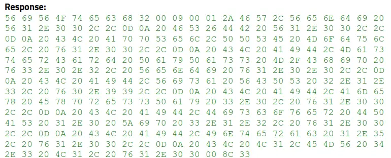
ASCII translation of the data field:
FW,Vendi V1.00,,<CR><LF>
FS&DB V1.00,,<CR><LF>
CL AppSel,PPSE Module, v1.00,,<CR><LF>
CL AID,MasterCard PayPass M/Chip v3.0.2, Vendi v1.0.0,,<CR><LF>
CL AID,Visa VCPS 2.1.3, v0.99,,<CR><LF>
CL AID,Amex ExpressPay 3.0, v1.00,,<CR><LF>
CL AID,Discover DPAS 1.0 Zip 3.1.2, v1.00,,<CR><LF>
CL AID,Interac 1.5, v1.00,,<CR><LF>
CL L1,EMV 4.3 L1, v1.00<NUL>
7.7. Get Serial Number (12-01)
The Get Serial Number command instructs the ViVOpay reader to return the 15-digit serial number stored in its non-volatile memory. If a serial number has not been previously set in the reader, this command fails with a Command Not Allowed error status. If the command frame is not valid, the reader returns an error response frame.
Command Frame
| Byte 0-9 | Byte 10 | Byte 11 | Byte 12 | Byte 13 | Byte 14 | Byte 15 |
| Header Tag & Protocol Version | Command | Sub- Command | Data Length (MSB) | Data Length (LSB) | CRC (LSB) | CRC (MSB) |
| ViVOtech2\0 | 12h | 01h | 00h | 0Fh |
The serial number will be returned tail-padded with 0x00 to a length of 15.
Example:
TX: 56 69 56 4F 74 65 63 68 32 00 12 01 00 00 18 A5
RX: 56 69 56 4F 74 65 63 68 32 00 12 00 00 0F 36 33 30 5A 30 30 30 30 30 31 00 00 00 00 00 94 BC
Response Frame
| Byte 0-9 | Byte 10 | Byte 11 | Byte 12 | Byte 13 | Byte 14 … Byte 14+n-1 | Byte 14+n | Byte 15+n |
| Header Tag & Protocol Version | Command | Sub- Command | Data Length (MSB) | Data Length (LSB) | Data | CRC (LSB) | CRC (MSB) |
| ViVOtech2\0 | 60h | 16h | 00h | 01h | ICS Identification |
7.8. Contact Set ICS Identification (60-16)
The Contact Set ICS Identification command sets the reader’s ICS terminal configuration number (Contact Command EMV L2 includes 4 approved configurations of certification: 1C, 2C, 3C, or 4C).
This command affects the Contact Set Terminal Data (60-06) command. Generally, readers call 60-16 first, then 60-06.
Examples: Set 3C configuration: 5669564f746563683200601600010392ed Reader responds with: 5669564f746563683200600000003d35 (Success)
Now set terminal data (TLVs) with config values appropriate to 3C: 5669564f746563683200600600c818005f3601029f1a0208409f3501259f330360d8 c89f40056000f050019f1e085465726d696e616c9f150212349f160f303030303030 3030303030303030309f1c0838373635343332319f4e2231303732312057616c6b65
722053742e20437970726573732c204341202c5553412edf260101df1008656e6672 65737a68df110101df270100dfee150101dfee160100dfee170107dfee180180dfee
1e08f0dc24f0c20e1400dfee1f0180dfee1b083030303135313030dfee20013cdfee 21010adfee2203323c3caa88
Reader responds with: 5669564f746563683200600000003d35 (Success)
Command Frame
| Byte 0-9 | Byte 10 | Byte 11 | Byte 12 | Byte 13 | Byte 14 … Byte 14+n-1 | Byte 14+n | Byte 15+n |
| Header Tag & Protocol Version | Command | Sub- Command | Data Length (MSB) | Data Length (LSB) | Data | CRC (LSB) | CRC (MSB) |
| ViVOtech2\0 | 60h | 16h | 00h | 01h | ICS Identification |
ICS Identification:
0x01 → Identification 1C
0x02 →Identification 2C (Default)
0x03 → Identification 3C
0x04 →Identification 4C
Response Frame
| Byte 0-9 | Byte 10 | Byte 11 | Byte 12 | Byte 13 | Byte 14 … Byte 14+n-1 | Byte 14+n | Byte 15+n |
| Header Tag & Protocol Version | Command | Status Code | Data Length (MSB) | Data Length (LSB) | Data | CRC (MSB) | CRC (LSB) |
| ViVOtech2\0 | 60h | See Status Code Table | 00 | 00 |
7.9. Contact Set Terminal Data (60-06)
The Contact Set Terminal Data command creates new terminal data according to the TLVs passed in. Terminal data is mandatory and seldom changes. It represents configuration data that usually gets set one time in pre-production and never changes after.
Command Frame
| Byte 0-9 | Byte 10 | Byte 11 | Byte 12 | Byte 13 | Byte 14 … Byte 14+n-1 | Byte 14+n | Byte 15+n |
| Header Tag & Protocol Version | Command | Sub- Command | Data Length (MSB) | Data Length (LSB) | Data | CRC (LSB) | CRC (MSB) |
| ViVOtech2\0 | 60h | 06h | Data Objects |
Data Objects: <TagCounterL><TagCounterH><TLV1><TLV2>…<TLVn>.
Where: <TagCounterL><TagCounterH>: the Number of <TLV> tags.
Response Frame
| Byte 0-9 | Byte 10 | Byte 11 | Byte 12 | Byte 13 | Byte 14 … Byte 14+n-1 | Byte 14+n | Byte 15+n |
| Header Tag & Protocol Version | Command | Status Code | Data Length (MSB) | Data Length (LSB) | Data | CRC (MSB) | CRC (LSB) |
| ViVOtech2\0 | 60h | See Status Code Table | See Response Frame Data Format |
Note: If a <TLV> format was bad, the response status code is 0x05. If flash error, the response status code is 0x62.
Terminal Data List Example
| Data ID | Tag | Value name | Length (Byte) | Data |
| 1 | 5F36 | Transaction currency exponent | 1 | 02 |
| 2 | 9F1A | Terminal county code | 2 | 08 40 |
| 3 | 9F35 | Terminal type | 1 | 21 |
| 4 | 9F33 | Terminal capability | 3 | 60 28 C8 |
| 5 | 9F40 | Additional terminal capability | 5 | F0 00 F0 A0 01 |
| 6 | 9F1E | IFD serial number | 8 | 54 65 72 6D 69 6E 61 6C |
| 7 | 9F15 | Merchant category code | 2 | 12 34 |
| 8 | 9F16 | Merchant identifier | 15 | 30 30 30 30 30 30 30 30 30 30 30 30 30 30 30 |
| 9 | 9F1C | Terminal identification | 8 | 38 37 36 35 34 33 32 31 |
| 10 | 9F4E | Merchant name and location | <=64 | 31 30 37 32 31 20 57 61 6C 6B 65 72 20 53 74 2E 20 43 79 70 72 65 73 73 2C 20 43 41 20 2C 55 53 41 2E |
| 11 | DF26 | Terminal supports CRL | 1 | 01 |
| 12 | DF10 | Language | Var. up to 128 | 65 6E 66 72 65 73 7A 68 |
| 13 | DF11 | Support transaction log | 1 | 00 |
| 14 | DF27 | support exception file | 1 | 00 |
| 15 | DFEE15 | Terminal support ASI | 1 | 01 |
| 16 | DFEE16 | Terminal encrypt mode | 1 | 00 |
| 17 | DFEE17 | Terminal entry mode for ICC | 1 | 07 |
| 18 | DFEE18 | Terminal encrypt mode for MSR | 1 | 80 |
| 19 | DFEE1E | Contact terminal configuration | 8 | D0 DC 20 D0 C4 1E 16 00 |
| 20 | DFEE1F | Issuer script limit | 1 | 80 |
| 21 | DFEE1B | ARC define | 8 | 30 30 30 31 35 31 30 30 |
| 22 | DFEE20 | ICC power on detect waiting time | 1 | 3C |
| 23 | DFEE21 | ICC L1 waiting time | 1 | 0A |
| 24 | DFEE22 | Driver waiting time. byte 1 -> Menu. byte 2 -> Get PIn. byte 3 -> MSR | 3 | 32 3C 3C |
The Contact Common EMV L2 comes with four approved configurations as shown below (1C, 2C, 3C, 4C); these correspond to the scenarios defined by EMVCo in tag 9F35. Parameters marked as Major Parameters usually cannot be changed without causing a checksum error, although certain flag bits (see tables below) can be changed. The Major Parameters are considered read-only because these are the settings the device was certified with for EMV L2 certification.
| Terminal configuration | |||||
| Identification | Tag | 1C | 2C | 3C | 4C |
| Major parameters | 9F33 | 60 F8 C8 | 60 28 C8 | 60 D8 C8 | 60 08 C8 |
| 9F35 | 22 | 21 | 25 | 25 | |
| 9F40 | F0 00 F0 A0 01 | F0 00 F0 A0 01 | 60 00 F0 50 01 | 60 00 F0 50 01 | |
| DF11 | 01 | 00 | 01 | 01 | |
| DF26 | 01 | 01 | 01 | 01 | |
| DF27 | 00 | 00 | 00 | 00 | |
| DFEE1E | F0 DC 3C F0 C2 9E 96 00 | D0 DC 20 D0 C4 1E 16 00 | F0 DC 24 F0 C2 0E 16 00 | D0 9C 20 F0 C2 0E 16 00 | |
| Tag | Description | Length | |||||||||||||||
| 9F33 | Terminal Capabilities Byte Byte 2 Byte 3 | 3 | |||||||||||||||
| b8 | b7 | b6 | b5 | b4 | b3 | b2 | b1 | Meaning | Change | ||||||||
| 1 | x | x | x | x | x | x | x | SDA | Major | ||||||||
| X | 1 | x | x | x | x | x | x | DDA | Major | ||||||||
| X | x | 1 | x | x | x | x | x | Card capture | |||||||||
| x | x | x | 0 | x | x | x | x | RFU | |||||||||
| x | x | x | x | 1 | x | x | X | CDA | Major | ||||||||
| x | x | x | x | x | 0 | x | x | RFU | |||||||||
| x | x | x | x | x | x | 0 | x | RFU | |||||||||
| x | x | x | x | X | X | x | 0 | RFU | |||||||||
| 9F35 | Terminal Type | 1 | |||||||||||||||
| Environment | Financial Institution | Merchant | Cardholder | Change | |||||||||||||
| Attended Online only Offline with online capability | 11 12 | 21 22 | — — | Major | |||||||||||||
| Offline only | 13 | 23 | — | ||||||||||||
| Unattended Online only Offline with online capability Offline only | 14 15 16 | 24 25 26 | 34 35 36 | Major | |||||||||||
| 9F40 | Additional Terminal Capabilities Byte 1 Byte 2 Byte 3 Byte 4 | 5 | |||||||||||||
| b8 | b7 | b6 | b5 | b4 | b3 | b2 | b1 | Meaning | Change | ||||||
| 1 | x | x | x | x | x | x | x | Print, attendant | |||||||
| x | 1 | x | x | x | x | x | x | Print, cardholder | |||||||
| x | x | 1 | x | x | x | x | x | Display, attendant | |||||||
| x | x | x | 1 | x | x | x | x | Display, cardholder | |||||||
| x | x | x | x | 0 | x | x | x | RFU | |||||||
| x | x | x | x | x | 0 | x | x | RFU | |||||||
| x | x | x | x | x | x | 1 | x | Code table 10 | Major | ||||||
| x | x | x | x | x | x | x | 1 | Code table 9 | Major | |||||||||||
| Byte 5 b8 b7 b6 b5 b4 b3 b2 b1 Meaning Change 1 x x x x x x x Code table 8 Major x 1 x x x x x x Code table 7 Major x x 1 x x x x x Code table 6 Major x x x 1 x x x x Code table 5 Major x x x x 1 x x x Code table 4 Major x x x x x 1 x x Code table 3 Major x x x x x x 1 x Code table 2 Major x x x x x x x 1 Code table 1 Major | ||||||||||||||||||||
| DF11 | Transaction Log Support (Default: Enable) (Major) 0 à Disable 1 à Enable | 1 | ||||||||||||||||||
| DF26 | Revocation List Support (Default: Enable) (Major) 0 à Disable 1 à Enable | 1 | ||||||||||||||||||
| DF27 | Exception File Support (Default: Disable) (Major) 0 à Disable 1 à Enable | 1 | ||||||||||||||||||
| DFEE1E | Contact Terminal Configuration (Default: F0 DC 3C F0 C2 9E 94 00) Byte 1 Byte 2 Byte 3 | |||||||||||||||||||
| b8 | b7 | b6 | b5 | b4 | b3 | b2 | b1 | Meaning | Change | |||||||||||
| 0 | x | x | x | x | x | x | x | RFU (Revocation of Issuer Public Key Certificate (DF26)) | Major | |||||||||||
| x | 1 | x | x | x | x | x | x | Manual action when CA PK loading fails | Major | |||||||||||
| x | x | 1 | x | x | x | x | x | CA PK verified with check sum | Major | ||||
| x | x | x | 1 | x | x | x | x | Bypass PIN Entry | Major | ||||
| x | x | x | x | 1 | x | x | x | Subsequent bypass PIN Entry | Major | ||||
| x | x | x | x | x | 1 | x | x | Get data for pin try counter | Major | ||||
| x | x | x | x | x | x | 0 | x | RFU | |||||
| x | x | x | x | x | x | x | 0 | RFU | |||||
| Byte 4
Byte 5
Byte 6
Byte 7 | |||||||||||||
| b8 | b7 | b6 | b5 | b4 | b3 | b2 | b1 | Meaning | Change | ||||
| 1 | x | x | x | x | x | x | x | amount and pin entered on the same keypad | |||||
| x | 1 | x | x | x | x | x | x | ICC/Magstripe reader combined | |||||
| x | x | 1 | x | x | x | x | x | Magstripe read first | |||||
| x | x | x | 1 | x | x | x | x | Support account type selection | |||||
| x | x | x | x | 1 | x | x | x | On fly script processing | |||||
| x | x | x | x | x | 1 | x | x | Internal date management | |||||
| x | x | x | x | x | x | 1 | x | Reversal Mode (1)Unable go online (2) ARC Error 0: (3) Online Approved but reader not approved. 1: (3) Online Approved but card response AAC. | |||||
| x | x | x | x | x | x | x | 0 | RFU | |||||
| Byte 8 | |||||||||||||
7.10. Contact Set Application Data (60-03)
The Contact Set Application Data command creates a new AID configuration, up to a maximum of 16 sets.
Command Frame
| Byte 0-9 | Byte 10 | Byte 11 | Byte 12 | Byte 13 | Byte 14 … Byte 14+n-1 | Byte 14+n | Byte 15+n |
| Header Tag & Protocol Version | Command | Sub- Command | Data Length (MSB) | Data Length (LSB) | Data | CRC (LSB) | CRC (MSB) |
| ViVOtech2\0 | 60h | 03h | Data Objects |
Data Objects: <AID_LenL><AID_LenH><5~16 bytes
AID><TagCounterL><TagCounterH><TLV1><TLV2>…<TLVn>.
Where: <TagCounterL><TagCounterH>is the Number of <TLV>.
Response Frame
| Byte 0-9 | Byte 10 | Byte 11 | Byte 12 | Byte 13 | Byte 14 … Byte 14+n-1 | Byte 14+n | Byte 15+n |
| Header Tag & Protocol Version | Command | Status Code | Data Length (MSB) | Data Length (LSB) | Data | CRC (MSB) | CRC (LSB) |
| ViVOtech2\0 | 60h | See Status Code Table | See Response Frame Data Format |
Note:
- If there was a <TLV> format error, the response status code is 0x05.
- If AID List is full (MAX is 16), the response status code is 0x61.
Application Data List Example
| Data ID | Tag | Value name | Length (Byte) | Data |
| 1 | 9F01 | Acquirer identifier | 6 | 56 49 53 41 30 30 |
| 2 | 5F57 | Account type | 1 | 00 |
| 3 | 5F2A | Transaction Currency | 2 | 08 40 |
| 4 | 9F09 | Terminal application version number | 2 | 00 96 |
| 5 | 5F36 | Transaction currency exponent | 1 | 02 |
| 6 | 9F1B | Terminal floor limit | 4 | 00 00 3A 98 |
| 7 | DF25 | Default DDOL | Var | 9F 37 04 |
| 8 | DF28 | Default TDOL | Var | 9F 08 02 |
| 9 | DFEE15 | ASI | 1 | 01 |
| 10 | DF13 | TAC-Default | 5 | 00 00 00 00 00 |
| 11 | DF14 | TAC-Denial | 5 | 00 00 00 00 00 |
| 12 | DF15 | TAC-Online | 5 | 00 00 00 00 00 |
| 13 | DF18 | Target percentage for random transaction selection | 1 | 00 |
| 14 | DF17 | Threshold value for biased random selection | 4 | 00 00 27 10 |
| 15 | DF19 | Maximum target percentage for random transaction selection | 1 | 00 |
Basic Card Reading Data Flow
The following examples describe the basic steps for setting a reader’s terminal settings and activating a transaction.
8.1. Example: Reading a Card via Firmware Commands
Perform the following steps and commands to read a card with the VP3350 via NEO 2 protocol firmware commands.
- Set the device’s terminal settings:
a. Run Set Kernel Configuration (60-16) to set the kernel configuration number, which acts as a filter to validate that the tags in the next step have the correct major parameters.
b. Run Set Terminal Configuration (60-06) to set the TLV tags, which must have the correct major parameters set in step 1a. - Run Contact Set Application Data (60-03) to set the device’s AID file. Note that, prior to
device certification, devices require dummy AIDs to function. - Run Activate Transaction (02-40) and read the card.
8.2. Example: Reading a Card via Universal SDK Methods
Perform the following steps and commands to read a card with the VP3350 via USDK methods.
- Set the device’s terminal settings:
a. Run Set Kernel Configuration: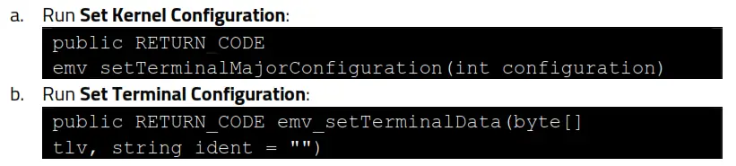
- Run Set Application Data:
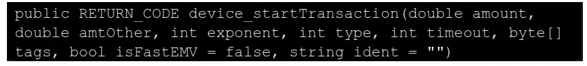
- Run Activate Transaction:

- Read the card.
8.3. Example: Reading a Card via the USDK Demo App
- Download and install the latest USDK Demo app from the ID TECH Knowledge Base (if you cannot access the link, please contact support).
- Connect the VP3350 to your PC via USB or serial port.
- Open the USDK Demo app from the Windows Start menu.
- Select EMV > Terminal Config > Set Kernel Config, then input the Config Number (example 2).
- Select EMV > Terminal Config > Save Terminal Data > Pick Tag List (example 2C) > Execute.
- Select EMV > AID > Load Default AID.
- Select EMV > Activate Transaction.
Application Development Considerations
When developing applications for the VP3350, make sure to consult the ID TECH Universal SDK Guide for your respective platform for best practices to follow. Download the Universal SDK Guide from the VP3350 product page as part of the ZIP file for your development platform.
ID TECH strongly recommends that integrators include a way for users to update their passwords.
9.1. Performing Key Injection on a VP3350 via Tablet
The VP3350 accepts key injection in two manners when integrated into a tablet:
- via RKI with the tablet running an application that supports ID TECH RKI (for example, an ID TECH application or ISV application)
- via the USB-C female port
Note: When performing key injection via the USB-C female port, the tablet must be turned off.
Using a Futurex machine requires the appropriate IDT-Futurex conversion box (ID TECH P/N : ID-80000001-012).
VP3350 Mounting and EMV Contactless Logo Requirements
Note that if the VP3350 is mounted behind any kind of casing or cover, that assembly MUST follow EMV requirements regarding contactless logo size and position. See EMVco Contactless Symbol Reproduction Requirements for details.
10.1. Contactless Mounting
To optimize performance, install VP3350 readers away from or in front of any metal surfaces or materials that have metallic content, which can interfere with the RF field. VP3350 readers perform optimally when mounted away from metal surfaces.
10.2. VP3350 Power Requirements and Mounting
When mounting the VP3350 to a surface or with another device (such as a tablet), use the ollowing guidelines:
- For the Bluetooth version of the VP3350, make sure to keep the power button accessible.
- The USB-C male and USB-C female versions of the VP3350 do not require an exposed power button as those models do not have internal batteries.
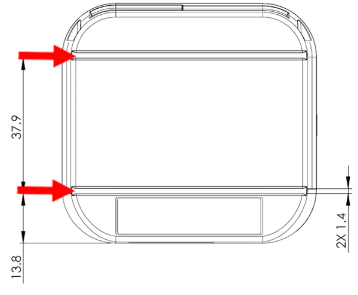
- If desired, use the two screw holes on the bottom side of unit and two recesses on the top side of unit highlighted below for mounting:
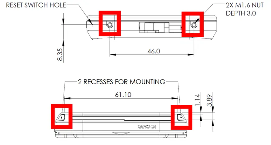
- Likewise, the VP3350 has slots on the back for alignment, shown bel
Periodic Inspection Instructions
The VP3350 is an attended device; contact an ID TECH representative with any questions for the device’s daily use.
Users are also required to complete the following checks daily:
- Check the device overlay to make sure it is intact.
- Power on the device to check the beeper and the display message:
o Make sure there is no beeping that indicates the tamper was triggered.
o Read the firmware version to make sure the version number is correct. - Check the device appearance to make sure there are no holes on the device or any suspicious objects around the ICC card slot.
Decommissioning PCI-Certified Devices
All PCI-certified devices require proper decommissioning prior to device disposal in order to ensure the protection of all sensitive financial card data. For instructions on decommissioning your device, see Decommissioning of PCI-Certified Devices on the ID TECH Knowledge Base.
Troubleshooting
The VP3350 is designed to be reliable and easy to troubleshoot. The components that may require troubleshooting include the power module (if applicable), the reader, and the serial cable.
| Symptom | Probable Cause | Remedy |
| General Issues | ||
| 4 RED LEDs blink and the device beeps | Unit has been tampered | Contact IDTECH Support |
| 4 Yellow blink and the device beeps | Unit was not activated | Contact IDTECH Support |
| 4 Yellow LEDs are on | LCL-KEK is not loaded or was erased | Contact IDTECH Support |
| 4 Green LEDs blink | DEK is not loaded or was erased | Contact IDTECH Support |
| No communication and all LEDs off | · Power off · Battery out of charge · Host device not connected | · Charge the battery · Press the device Reset button · Make sure to enter the correct paring password |
| Bluetooth paring failed | · Host device running Android 6.x or earlier · Mobile does not work in BLE security mode | · Make sure the host device is running Android 6.x or later |
| Reader does not appear to be powered on after pressing the power button (no LEDs are lit) | · Reader not powered on · Battery out of charge | · Connect the device to PC via a USB cable · Replace the device with another unit known to work to verify that the installed USB cable wiring works correctly |
| Some cards or fobs read, but not all | · Possible bad card or fob. · Unsupported card used. · Wrong firmware | · Check to see if the card or fob is damaged · Verify that the correct firmware is loaded on reader; contact your ID TECH representative |
| LEDs do not light and the beeper is not audible when presenting a card or fob | · Card, fob, or phone not properly presented · RF interference · Unsupported card used · Wrong firmware | · Present card, fob, or phone closer to the antenna and ensure it is parallel to the face of the reader · Verify that the card, fob, or phone is valid and current · Verify that metal is not interfering with the antenna · Test with ViVOcard Contactless Test Card part number 241-0015-03, Rev A · Try a different card, fob, or phone · Check to see if the card, fob, or phone is damaged · Verify that correct firmware is loaded on reader; contact your ID TECH representative · Power cable plug is fully inserted · Make sure device is not set to Passthrough mode · Replace the unit |
| Communication Issues | ||
| No data received or data is garbled | Faulty or incorrect cable connections. | Check that the cable connection is secure and in the correct port on the device |
| Fail to start transaction, 0x0B returned | Device in Passthrough mode or transaction mode | · Need to exit Passthrough mode · Need to cancel transaction |
| Symptom | Probable Cause | Remedy |
| Fail to start transaction, 0x60 returned | No terminal data or application data | Need to load terminal data or application data for Contact EMV transactions |
| Fail to start transaction, 0x04 returned | Missing Key | Please re-start VP3350 and monitor the LEDs to confirm whether to Load LCL key or Data Key |
| Firmware loading software indicates “Open device failed” | Device is not fully connected to PC | · Check the cable connection · Check the device |
| Firmware loading software indicates “Load firmware failed” | Device is not fully connected to PC | Check the cable connections |
| Firmware loading software indicates “Send Command failed” | Bootloader firmware in device was destroyed | Contact your ID TECH representative to reload manufacture’s firmware |
If you are unable to resolve the problem, please contact [email protected] (sending an e-mail to this address will automatically open a support ticket).
13.1. Tamper Detection Codes
If a tamper event occurs, the VP3350 stores a tamper code in its security log. Check the security log with the Get DRS Info (C7-3A) command; see the NEO 2 Interface Developer’s Guide for details.
| Tamper Event Type | Code |
| EVENT_TYPE_TAMPER_ACTIVE | 0 |
| EVENT_TYPE_TAMPER_DEACTIVE | 1 |
| EVENT_TYPE_TAMPER_GENERIC | 2 |
| EVENT_TYPE_TAMPER_ACK | 3 |
| EVENT_TYPE_TAMPER_TIMEOVRF | 4 |
| EVENT_TYPE_TAMPER_MONOTONICOVRF | 5 |
| EVENT_TYPE_TAMPER_VOLT | 6 |
| EVENT_TYPE_TAMPER_CLK | 7 |
| EVENT_TYPE_TAMPER_TEMP | 8 |
| EVENT_TYPE_TAMPER_FLASH | 9 |
| EVENT_TYPE_TAMPER_TST | 10 |
| EVENT_TYPE_TAMPER_PIN | 11 |
| EVENT_TYPE_TAMPER_BAT | 12 |
| EVENT_TYPE_TAMPER_ALL | 255 |
For More Information
- To learn more about VP3350 and other ID TECH products, visit the ID TECH Knowledge Base.
- To learn more about EMV app development with the Universal SDK, see EMV
Transactions with Universal SDK. - Visit us online at http://idtechproducts.com.
- Find more Tech Support resources at the ID TECH Tech Support home page.


