
![]()
Electronic Hand Grinder
GP 3V · GP 5V
HANDLING INSTRUCTIONS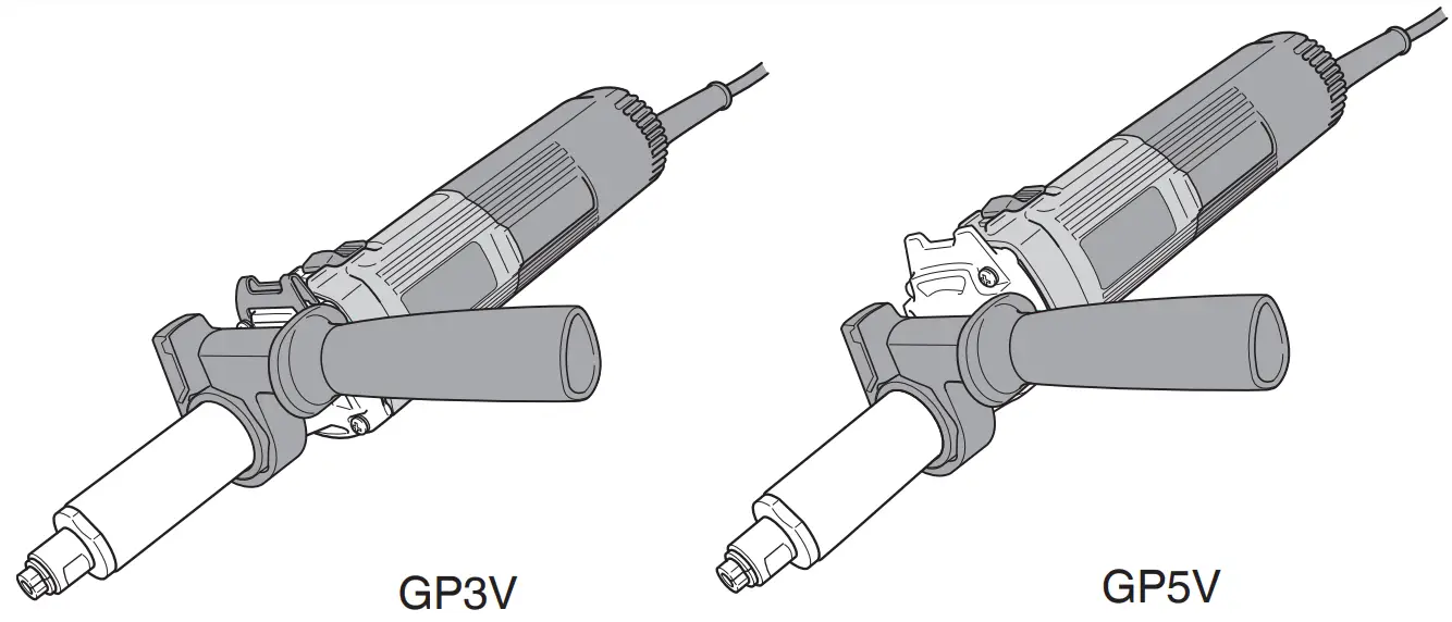
 Read through carefully and understand these instructions before use.
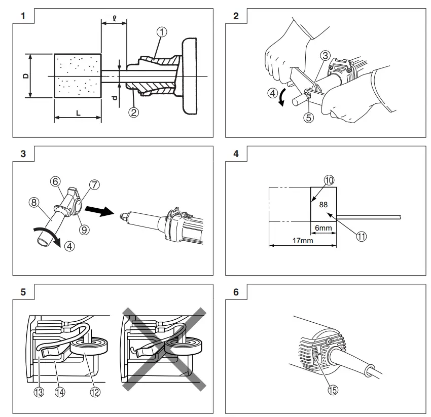
| 1 | Tapered portion |
| 2 | Collet chuck |
| 3 | Spindle |
| 4 | Tighten |
| 5 | Collet chuck |
| 6 | Side handle |
| 7 | Side handle sleeve |
| 8 | Side handle grip |
| 9 | Flange part |
| 10 | Wear limit |
| 11 | No. of carbon brush |
| 12 | Spring |
| 13 | Carbon brush |
| 14 | Brush holder |
| 15 | Dial |
GENERAL SAFETY RULES
WARNING! Read all instructions
Failure to follow all instructions listed below may result in electric shock, fire and/or serious injury. The term “power tool” in all of the warnings listed below refers to your mains operated (corded) power tool or battery operated (cordless) power tool.
SAVE THESE INSTRUCTIONS
1) Work area
a) Keep the work area clean and well-lit. Cluttered and dark areas invite accidents.
b) Do not operate power tools in explosive atmospheres, such as in the presence of flammable liquids, gases or dust. Power tools create sparks which may ignite the dust of fumes.
c) Keep children and bystanders away while operating a power tool. Distractions can cause you to lose control.
2) Electrical safety
a) Power tool plugs must match the outlet. Never modify the plug in any way. Do not use any adapter plugs with earthed (grounded) power tools. Unmodified plugs and matching outlets will reduce the risk of electric shock.
b) Avoid body contact with earthed or grounded surfaces such as pipes, radiators, ranges, and refrigerators. There is an increased risk of electric shock if your body is earthed or grounded.
c) Do not expose power tools to rain or wet conditions. Water entering a power tool will increase the risk of electric shock.
d) Do not abuse the cord. Never use the cord for carrying, pulling, or unplugging the power tool. Keep cord away from heat, oil, sharp edges, or moving parts. Damaged or entangled cords increase the risk of electric shock.
e) When operating a power tool outdoors, use an extension cord suitable for outdoor use. The use of a cord suitable for outdoor use reduces the risk of electric shock.
3) Personal safety
a) Stay alert, watch what you are doing, and use common sense when operating a power tool. Do not use a power tool while you are tired or under the influence of drugs, alcohol or medication. A moment of inattention while operating power tools may result in serious personal injury.
b) Use safety equipment. Always wear eye protection. Safety equipment such as dust masks, non-skid safety shoes, hard hats, or hearing protection used for appropriate conditions will reduce personal injuries.
c) Avoid accidental starting. Ensure the switch is in the off position before plugging in. Carrying power tools with your finger on the switch or plugging in power tools that have the switch on invites accidents.
d) Remove any adjusting key or wrench before turning the power tool on. A wrench or a key left attached to a rotating part of the power tool may result in personal injury.
e) Do not overreach. Keep proper footing and balance at all times. This enables better control of the power tool in unexpected situations.
f) Dress properly. Do not wear loose clothing or jewelry. Keep your hair, clothing, and gloves away from moving parts. Loose clothes, jewelry or long hair can be caught in moving parts.
g) If devices are provided for the connection of dust extraction and collection facilities, ensure these are connected and properly used. Use of these devices can reduce dust-related hazards.
4) Power tool use and care
a) Do not force the power tool. Use the correct power tool for your application. The correct power tool will do the job better and safer at the rate for which it was designed.
b) Do not use the power tool if the switch does not turn it on and off. Any power tool that cannot be controlled with the switch is dangerous and must be repaired.
c) Disconnect the plug from the power source before making any adjustments, changing accessories, or storing power tools. Such preventive safety measures reduce the risk of starting the power tool accidentally.
d) Store idle power tools out of the reach of children and do not allow persons unfamiliar with the power tool or these instructions to operate the power tool. Power tools are dangerous in the hands of untrained users.
e) Maintain power tools. Check for misalignment or binding of moving parts, breakage of parts, and any other condition that may affect the power tools operation. If damaged, have the power tool repaired before use. Many accidents are caused by poorly maintained power tools.
f) Keep cutting tools sharp and clean. Properly maintained cutting tools with sharp cutting edges are less likely to bind and are easier to control.
g) Use the power tool, accessories and tool bits, etc., in accordance with these instructions and in the manner intended for the particular type of power tool, taking into account the working conditions and the work to be performed. Use of the power tool for operations different from intended could result in a hazardous situation.
5) Service
a) Have your power tool serviced by a qualified repair person using only identical replacement parts. This will ensure that the safety of the power tool is maintained.
PRECAUTION
Keep children and infirm persons away. When not in use, tools should be stored out of reach of children and infirm persons.
SAFETY WARNINGS COMMON FOR GRINDING
OPERATIONS
a) This power tool is intended to function as a grinder. Read all safety warnings, instructions, illustrations and specifications provided with this power tool. Failure to follow all instructions listed below may result in electric shock, fire and/or serious injury.
b) Operations such as sanding, polishing, wire brushing or cutting-off are not recommended to be performed with this power tool. Operations for which the power tool was not designed may create a hazard and cause personal injury.
c) Do not use accessories that are not specifically designed and recommended by the tool manufacturer. Just because the accessory can be attached to your power tool, it does not assure safe operation.
d) The rated speed of the accessory must be at least equal to the maximum speed marked on the power tool. Accessories running faster than their rated speed can break and fly apart.
e) The outside diameter and the thickness of your accessory must be within the capacity rating of your power tool. Incorrectly sized accessories cannot be adequately guarded or controlled.
f) The arbor size of wheels, flanges, backing pads or any other accessory must properly fit the spindle of the power tool. Accessories with arbor holes that do not match the mounting hardware of the power tool will run out of balance, vibrate excessively, and may cause loss of control.
g) Do not use a damaged accessory. Before each use inspects the accessory such as abrasive wheels for chips and cracks, backing pad for cracks, tear or excess wear, and wire brush for loose or cracked wires. If a power tool or accessory is dropped, inspect for damage or install an undamaged accessory. After inspecting and installing an accessory, position yourself and bystanders away from the plane of the rotating accessory and run the power tool at maximum no-load speed for one minute. Damaged accessories will normally break apart during this test time.
h) Wear personal protective equipment. Depending on the application, use a face shield, safety goggles or safety glasses. As appropriate, wear a dust mask, hearing protectors, gloves, and a workshop apron capable of stopping small abrasive or workpiece fragments. The eye protection must be capable of stopping flying debris generated by various operations. The dust mask or respirator must be capable of filtrating particles generated by your operation. Prolonged exposure to high-intensity noise may cause hearing loss.
i) Keep bystanders a safe distance away from the work area. Anyone entering the work area must wear personal protective equipment. Fragments of a workpiece or of a broken accessory may fly away and cause injury beyond the immediate area of operation.
j) Hold power tool by insulated gripping surfaces only, when performing an operation where the cutting accessory may contact hidden wiring or its own cord. Cutting accessory contacting a “live” wire may make exposed metal parts of the power tool “live” and shock the operator.
k) Position the cord clear of the spinning accessory. If you lose control, the cord may be cut or snagged and your hand or arm may be pulled into the spinning accessory.
l) Never lay the power tool down until the accessory has come to a complete stop. The spinning accessory may grab the surface and pull the power tool out of your control.
m) Do not run the power tool while carrying it at your side. Accidental contact with the spinning accessory could snag your clothing, pulling the accessory into your body.
n) Regularly clean the power tool’s air vents. The motor’s fan will draw the dust inside the housing and excessive accumulation of powdered metal may cause electrical hazards.
o) Do not operate the power tool near flammable materials. Sparks could ignite these materials.
p) Do not use accessories that require liquid coolants. Using water or other liquid coolants may result in electrocution or shock.
KICKBACK AND RELATED WARNINGS
Kickback is a sudden reaction to a pinched or snagged rotating wheel, backing pad, brush or any other accessory. Pinching or snagging causes rapid stalling of the rotating accessory which in turn causes the uncontrolled power tool to be forced in the direction opposite of the accessory’s rotation at the point of the binding. For example, if an abrasive wheel is snagged or pinched by the workpiece, the edge of the wheel that is entering into the pinch point can dig into the surface of the material causing the wheel to climb out or kick out. The wheel may either jump toward or away from the operator, depending on the direction of the wheel’s movement at the point of pinching. Abrasive wheels may also break under these conditions. Kickback is the result of power tool misuse and/or incorrect operating procedures or conditions and can be avoided by taking proper precautions as given below.
a) Maintain a firm grip on the power tool and position your body and arm to allow you to resist kickback forces. Always use an auxiliary handle, if provided, for maximum control over kickback or torque reaction during start-up. The operator can control torque reactions or kickback forces if proper precautions are taken.
b) Never place your hand near the rotating accessory. The accessory may kick back over your hand.
c) Do not position your body in the area where the power tool will move if kickback occurs. Kickback will propel the tool in a direction opposite to the wheel’s movement at the point of snagging.
d) Use special care when working corners, sharp edges etc. Avoid bouncing and snagging the accessory. Corners, sharp edges or bouncing have a tendency to snag the rotating accessory and cause loss of control or kickback.
e) Do not attach a saw chain woodcarving blade or toothed saw blade. Such blades create frequent kickback and loss of control.
SAFETY WARNINGS SPECIFIC FOR GRINDING OPERATION
a) Use only wheel types that are recommended for your power tool and the specific guard designed for the selected wheel. Wheels for which the power tool was not designed cannot be adequately guarded and are unsafe.
b) Wheels must be used only for recommended applications. For example: do not grind with the side of the cut-off wheel. Abrasive cut-off wheels are intended for peripheral grinding, side forces applied to these wheels may cause them to shatter.
c) Always use undamaged wheel flanges that are of the correct size and shape for your selected wheel. Proper wheel flanges support the wheel thus reducing the possibility of wheel breakage. Flanges for cut-off wheels may be different from grinding wheel flanges.
d) Do not use worn-down wheels from larger power tools. The wheel intended for a larger power tool is not suitable for the higher speed of a smaller tool and may burst.
GENERAL SAFETY INSTRUCTIONS FOR GRINDERS
- Check that speed marked on the wheel is equal to or greater than the rated speed of the grinder;
- Ensure that the wheel dimensions are compatible with the grinder;
- Abrasive wheels shall be stored and handled with care in accordance with the manufacturer’s instructions
- Inspect the grinding wheel before use, do not use chipped, cracked or otherwise defective products;
- Ensure that mounted wheels and points are fitted in accordance with the manufacturer’s instructions;
- Ensure that blotters are used when they are provided with the bonded abrasive product and when they are required;
- Ensure that the abrasive product is correctly mounted and tightened before use and run the tool at no load for 30 s in a safe position, stop immediately if there is considerable vibration or if other defects are detected. If this condition occurs, check the machine to determine the cause;
- If a guard is equipped with the tool never use the tool without such a guard;
- Do not use separate reducing bushings or adapters to adapt large hole abrasive wheels
- For tools intended to be fitted with threaded hole wheel, ensure that the thread in the wheel is long enough to accept the spindle length;
- Check that the work piece is properly supported;
- Do not use cutting off wheel for side grinding;
- Ensure that sparks resulting from use do not create a hazard e.g. do not hit persons, or ignite flammable substances;
- Ensure that ventilation openings are kept clear when working in dusty conditions, if it should become necessary to clear dust, first disconnect the tool from the mains supply (use nonmetallic objects) and avoid damaging internal parts;
- Always use eye and ear protection. Other personal protective equipment such as a dust mask, gloves, helmet, and apron should be worn;
- Pay attention to the wheel that continues to rotate after the tool is switched off.
SPECIFICATIONS
| Model | GP3V | GP5V |
| Voltage (by areas)* | (110 V, 120 V, 127 V, 220 V, 230 V, 240 V) | |
| Power Input* | 760 W | |
| No-Load Speed* | 7000 – 29000 /min | 2000 – 8300 /min |
| Rated speed* | 30800 /min | 8820 /min |
| Max. Wheel Diam.* | 25 mm | 50 mm |
| Collet chuck Capacity** | 6 mm | 6 mm |
| Weight (without cord) | 1.8 kg | 1.9 kg |
* Be sure to check the nameplate on the product as it is subject to change by areas. ** This varies depending on the area.
Electronic Control
- The grinder has an electronic speed control which provides:
- full speed at all times in the range up to rated load.
- soft-start. variable speed
NOTE:
The grinder is equipped with a rotational speed control circuit. The rotational speed may fluctuate slightly due to the conditions of use and working voltage.
STANDARD ACCESSORIES
(1) Wrench (17 mm) …………………………………………………..1 (2)
Wrench (12 mm) …………………………………………………..1 (3)
Side handle (not included by areas)…………………………1
Standard accessories are subject to change without notice.
OPTIONAL ACCESSORIES (sold separately)
- Collet chuck
for 3 mm shaft
for 3.175 mm (1/8″) shaft
for 6.35 mm (1/4″) shaft
for 8 mm shaft - Dimensions and handling methods other than the shaft hole are the same as those for the 6 mm collet chuck.
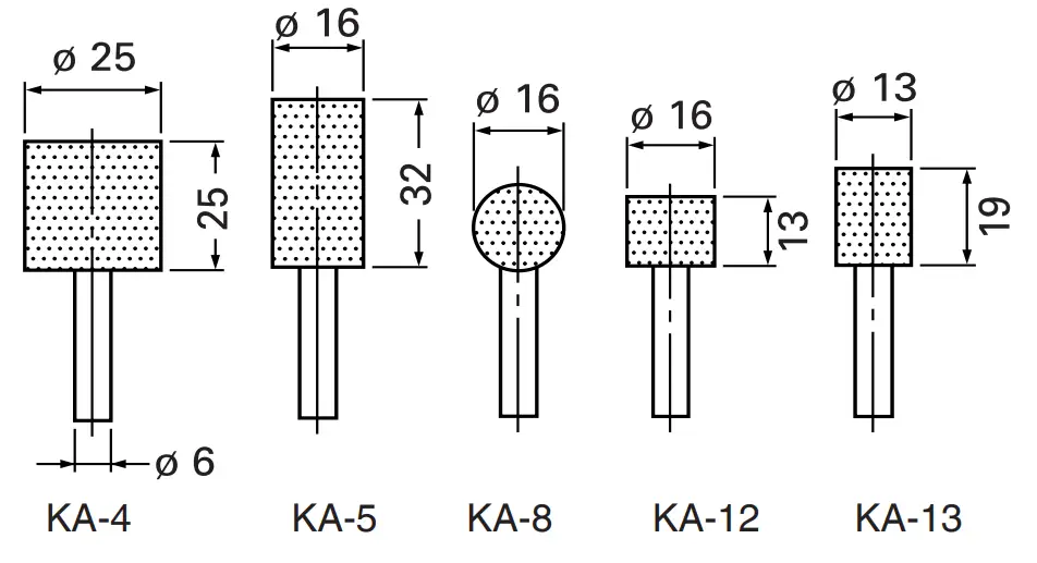
- Wheels with 6 mm shaft All wheels are provided with WA grain, 60 granding, and P bonding and are suitable for grinding general and special steel materials.
Wheels with 3 mm shaft
All wheels are provided with WA grain, 80 grinding and P bonding and are suitable for grinding general and special steel materials.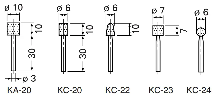
Dresser
Case
Optional accessories are subject to change without notice.
APPLICATIONS
- Finishing of dies for press work, die casting and molding.
- Finishing of thread cutting dies, tools, and other small parts.
- Internal grinding of tools and machine parts.
PRIOR TO OPERATION
- Power source
Ensure that the power source to be utilized conforms to the power requirements specified on the product nameplate.
NOTE: When connected to the power supply, the built-in electronic control circuit shifts to standby status and the grinder becomes slightly warm, but this is not a malfunction.
CAUTION Do not operate from a direct current power source, engine generator, booster or any other type of transformer. Doing so may not only cause damage to the grinder but may lead to accidents. - Power switch
Ensure that the power switch is in the OFF position. If the plug is connected to a receptacle while the power switch is in the ON position, the power tool will start operating immediately, inviting serious accidents. - Extension cord
When the work area is removed from the power source. Use an extension cord of sufficient thickness and rated capacity. The extension cord should be kept as short as practicable. - Installing a wheel
Install the wheel so that the length is less than 15 mm. If is longer, abnormal vibration will occur, and the machine is not only negatively affected, but there is a possibility of a serious accident.
Make the as small as possible.
When d = 6 mm, 6.35 mm (1/4″), 8 mm, D of the wheel should be less than the Max. wheel diam. of each model (GP3V: 25 mm, GP5V: 50 mm). If a wheel with D is more than the Max. wheel diam. of each model (GP3V: 25 mm, GP5V: 50 mm) is used, the circumference speed exceeds the safety limit and the wheel will break. Never use such a wheel. Distance L varies for D.
Determine L by referring to the table below.
When d = 3 mm, 3.175 mm (1/8″), D should be less than 10 mm.
Determine L referring to the table below.
Wheels can be simply attached and detached by using the two wrenches (Fig. 2).
NOTE
Do not tighten the collet chuck by inserting a shaft thinner than the regular shaft diameter (6 mm) in the chuck or in an empty condition. This practice will damage the collet chuck. When installing a wheel with a shaft, tighten the collet chuck after applying a small quantity of spindle oil (or sewing machine oil) to the tapered portion indicated in Fig. 1.
GP3V
| d | 3 mm, 3.175 mm (1/8”) | 6 mm, 6.35 mm (1/4”) | 8 mm | ||||||
| D | 5 mm | 6 mm | 8 mm | 10 mm | 13 mm | 16 mm | 20 mm | 25 mm | 25 mm |
| L | 10 mm | 13 mm | 16 mm | 13 mm | 40 mm | 40 mm | 25 mm | 25 mm | 32 mm |
GP5V
| d | 3 mm, 3.175 mm (1/8”) | 6 mm, 6.35 mm (1/4”) | 8 mm | ||||||||||
| D | 5 mm | 6 mm | 8 mm | 10 mm | 13 mm | 16 mm | 20 mm | 25 mm | 32 mm | 38 mm | 25 mm | 32 mm | 38 mm |
| L | 10 mm | 13 mm | 16 mm | 13 mm | 40 mm | 40 mm | 25 mm | 25 mm | 13 mm | 7 mm | 32 mm | 25 mm | 19 mm |
5. Adjusting the number of revolution
These models are equipped with an electronic infinite variable-speed drive and can change the number of revolutions according to use. If you turn and set the dial scale (Fig. 6) to 6, the number of revolutions increases, and if you turn and set it to 1, the number of revolutions decreases. Before use, set the number of revolutions using the dial.
In so doing, refer to the following table as a rough guide.
| Dial | Use | Rotation speed (/min) | |
| GP3V | GP5V | ||
| 1 | Polishing, finishing | 7000 | 2000 |
| 2 | Removal of paint or coat | 11400 | 3250 |
| 3 | Removal of rust | 15800 | 4500 |
| 4 | Removal of burrs | 20200 | 5800 |
| 5 | Grinding | 24600 | 7050 |
| 6 | Rough grinding | 29000 | 8300 |
NOTE: Use caution not to turn the dial scale to any value below 1 or above 6.
6. Caution when using near welding equipment
When using the grinder in the immediate vicinity of welding equipment, the rotational speed may become unstable. Do not use the grinder near welding equipment.
7. Using the side handle (Fig. 3)
Be sure to use the side handle to avoid the risk of severe electrical shock. Attach the side handle to the machine as follows.
(1) Loosen the side handle grip and insert the side handle to the nose bracket part of the machine from the flange part of the side handle sleeve.
(2) Set the side handle to a position that is suited to the operation and then securely tighten the side handle grip.
HOW TO USE
1. Switching operation
- When moving the switch lever to the right (ON side), power is applied; when moving it to the left (OFF side), power is switched off.
- When first turning on the switch after installing a new wheel, hold the grinder away from your body to avoid any danger of a wheel shattering due to imperfection.
- Before starting, test the machine with the wheel pointed in a safe direction.
2. Precautions on the operation
- Lightly press the wheel to the material to be ground. When grinding materials, a high-speed revolution is necessary. Use a hand grinder with high-speed revolution, minimizing the pressing force.
CAUTION When using the tool at any value except the full speed (Dial scale 6), the motor cannot be sufficiently cooled due to the decreased number of revolutions. This could result in the risk of burning and damaging the motor before an overload protective mechanism starts to function. Make sure that you use the tool by lightly applying it to the surface of the material when you use it at any value except the full speed (Dial scale 6). - Dressing the wheel After attaching a wheel, correct deflection of the wheel center by using a dresser. If the wheel center is eccentric, not only precise finishing cannot be achieved but also grinder vibration increases, lowering grinder accuracy and durability. A clogged or worn wheel will spoil the finishing surface or lower the grinding efficiency. Occasionally dress the wheel by applying the dresser.
WHEEL SELECTING METHOD
Types of wheels are varied according to the materials to be ground. Select a wheel appropriate for the material to be ground.
The following table is an outline of wheels and materials to be ground.
| Materials to be ground | Grain | Grading | Bonding degree | Structure | Bonding agent |
| Mild steel, hard steel, forged steel | WA | 60 – 80 | P | m | V |
| Cast iron | C | 36 | M – O | m | V |
| Brass, bronze, aluminum | C | 36 | J – K | m | V |
| Ceramic | WA | 60 – 80 | M | m | V |
| Synthetic resin | C | 36 | K – M | m | V |
Small-scaled wheels with shafts are prepared for grinding small surfaces. Their dimensions and shapes are shown in “OPTIONAL ACCESSORIES”. Since wheel shaft diameter is 3 mm, use the collet chuck for 3 mm shaft sold separately by your HiKOKI dealer as an optional accessory.
MAINTENANCE AND INSPECTION
- Inspecting the wheel Ensure that the wheel is free of cracks and surface defects.
- Inspecting the mounting screws Regularly inspect all mounting screws and ensure that they are properly tightened. Should any of the screws be loose, retighten them immediately. Failure to do so could result in serious hazards.
- Maintenance of the motor unit winding is the very “heart” of the power tool. Exercise due care to ensure the winding does not become damaged and/or wet with oil or water.
- Inspecting the carbon brushes (Fig. 4) The motor employs carbon brushes which are consumable parts. Since an excessively worn carbon brush can result in motor trouble, replace the carbon brushes with new ones having the same carbon brush No. shown in the figure when it becomes worn to or near the “wear limit”. In addition, always keep carbon brushes clean and ensure that they slide freely within the brush holders.
- Replacing a carbon brush (Fig. 5)
<Disassembly>
(1) Loosen the D4 tapping screw retaining the tail cover and remove the tail cover.
(2) Use the auxiliary hexagonal wrench or small screwdriver to pull up the edge of the spring that is holding down the carbon brush. Remove the edge of the spring toward the outside of the brush holder.
(3) Remove the end of the pig-tail on the carbon brush from the terminal section of brush holder and then remove the carbon brush from the brush holder.
<Assembly>
(1) Insert the end of the pig-tail of the carbon brush in the terminal section of the brush holder.
(2) Insert the carbon brush in the brush holder.
(3) Use the auxiliary hexagonal wrench or small screwdriver to return the edge of the spring to the head of the carbon brush.
NOTE: Make sure the end of the spring is not holding the pigtail.
(4) Mount the tail cover and tighten the D4 tapping screw. - Service parts list
CAUTION Repair, modification and inspection of HiKOKI Power Tools must be carried out by a HiKOKI Authorized Service Center. This Parts List will be helpful if presented with the tool to the HiKOKI Authorized Service Center when requesting repair or other maintenance. In the operation and maintenance of power tools, the safety regulations and standards prescribed in each country must be observed.
MODIFICATIONS HiKOKI Power
Tools are constantly being improved and modified to incorporate the latest technological advancements. Accordingly, some parts may be changed without prior notice.
NOTE
Due to HiKOKI’s continuing program of research and development, the specifications herein are subject to change without prior notice.
GP3V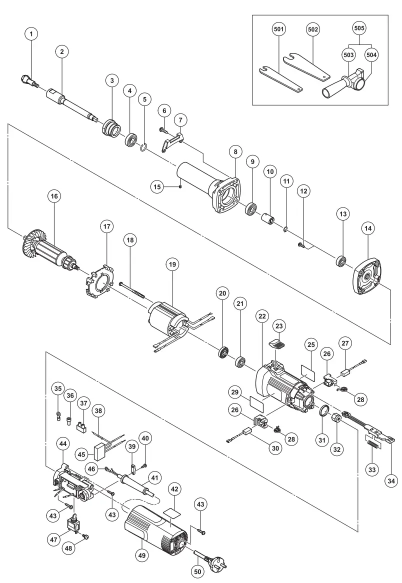
Item No. | Part Name | Q’TY |
| 1 | COLLET CHUCK | 1 |
| 2 | SPINDLE | 1 |
| 3 | BEARING LID (B) | 1 |
| 4 | BALL BEARING 6001VVCMPS2L | 1 |
| 5 | RING | 1 |
| 6 | TAPPING SCREW (W/SP. WASHER) D5 × 30 | 4 |
| 7 | GUARD PLATE | 1 |
| 8 | NOSE BRACKET | 1 |
| 9 | BALL BEARING 6000VVCMPS2L | 1 |
| 10 | COUPLING | 1 |
| 11 | RETAINING RING FOR D8 SHAFT | 1 |
| 12 | SEAL LOCK SCREW (W/SP. WASHER) M4 × 10 | 2 |
| 13 | BALL BEARING 609VVC2PS2L | 1 |
| 14 | INNER COVER | 1 |
| 15 | HEX. SOCKET SET SCREW M4 × 4 | 1 |
| 16 | ARMATURE | 1 |
| 17 | FAN GUIDE | 1 |
| 18 | HEX. HD. TAPPING SCREW D4 × 70 | 2 |
| 19 | STATOR | 1 |
| 20 | DUST SEAL | 1 |
| 21 | BALL BEARING 608VVC2PS2L | 1 |
| 22 | HOUSING | 1 |
| 23 | SLIDE KNOB | 1 |
| 25 | NAMEPLATE | 1 |
| 26 | BRUSH HOLDER | 2 |
| 27 | CARBON BRUSH | 1 |
| 28 | SPRING | 2 |
| 29 | BRAND LABEL | 1 |
| 30 | CARBON BRUSH | 1 |
| 31 | RUBBER RING | 1 |
| 32 | MAGNET | 1 |
| 33 | SPRING | 1 |
| 34 | SLIDE BAR | 1 |
| 35 | TERMINAL M4.0 | 1 |
Item No. | Part Name | Q’TY |
| 36 | CONNECTOR 50091 | 1 |
| 37 | PILLAR TERMINAL | 1 |
| 38 | EARTH TERMINAL | 1 |
| 39 | CORD CLIP | 1 |
| 40 | TAPPING SCREW (W/FLANGE) D4 × 16 | 2 |
| 41 | CORD ARMOR | 1 |
| 42 | SETTING LABEL (B) | 1 |
| 43 | TAPPING SCREW (W/FLANGE) D4 × 20 | 3 |
| 44 | CONTROLLER | 1 |
| 45 | NOISE SUPPRESSOR | 1 |
| 46 | TERMINAL | 1 |
| 47 | SWITCH | 1 |
| 48 | MACHINE SCREW (W/WASHER) M3.5 × 6 | 2 |
| 49 | TAIL COVER | 1 |
| 50 | CORD | 1 |
| 501 | WRENCH | 1 |
| 502 | WRENCH | 1 |
| 503 | SIDE HANDLE | 1 |
| 504 | FLANGED SLEEVE | 1 |
| 505 | SIDE HANDLE SLEEVE ASS’Y | 1 |
GP5V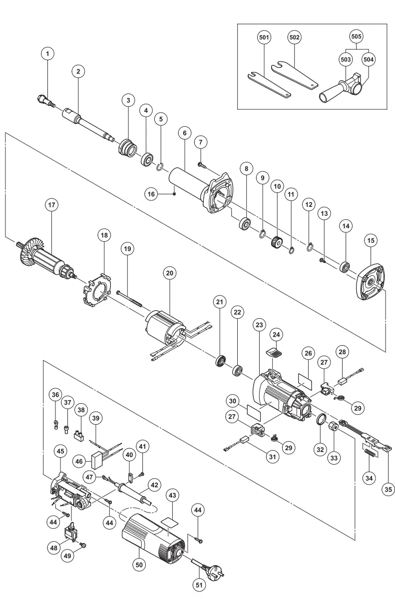
Item No. | Part Name | Q’TY |
| 1 | COLLET CHUCK | 1 |
| 2 | SPINDLE | 1 |
| 3 | BEARING LID(B) | 1 |
| 4 | BALL BEARING 6001VVCMPS2L | 1 |
| 5 | RING | 1 |
| 6 | NOSE BRACKET | 1 |
| 7 | TAPPING SCREW (W/SP. WASHER) D5 × 30 | 4 |
| 8 | BALL BEARING 6000VVCM PS2L | 1 |
| 9 | RETAINING RING FOR D10 SHAFT | 1 |
| 10 | FIRST GEAR | 1 |
| 11 | RETAINING RING FOR D8 SHAFT | 1 |
| 12 | RETAINING RING | 1 |
| 13 | SLOTTED HD. SCREW (SEAL LOCK) M4 × 8 | 2 |
| 14 | BALL BEARING 609VVC2PS2L | 1 |
| 15 | INNER COVER | 1 |
| 16 | HEX. SOCKET SET SCREW M4 × 4 | 1 |
| 17 | ARMATURE | 1 |
| 18 | FAN GUIDE | 1 |
| 19 | HEX. HD. TAPPING SCREW D4 × 70 | 2 |
| 20 | STATOR | 1 |
| 21 | DUST SEAL | 1 |
| 22 | BALL BEARING 608VVC2PS2L | 1 |
| 23 | HOUSING | 1 |
| 24 | SLIDE KNOB | 1 |
| 26 | NAME PLATE | 1 |
| 27 | BRUSH HOLDER | 2 |
| 28 | CARBON BRUSH | 1 |
| 29 | SPRING | 2 |
| 30 | BRAND LABEL | 1 |
| 31 | CARBON BRUSH | 1 |
| 32 | RUBBER RING | 1 |
| 33 | MAGNET | 1 |
| 34 | SPRING | 1 |
| 35 | SLIDE BAR | 1 |
| Item No. | Part Name | Q’TY |
| 36 | TERMINAL M4.0 (10 PCS.) | 1 |
| 37 | CONNECTOR 50091 (10 PCS.) | 1 |
| 38 | PILLAR TERMINAL | 1 |
| 39 | EARTH TERMINAL | 1 |
| 40 | CORD CLIP | 1 |
| 41 | TAPPING SCREW (W/FLANGE) D4 × 16 | 2 |
| 42 | CORD ARMOR | 1 |
| 43 | SETTING LABEL(B) | 1 |
| 44 | TAPPING SCREW (W/FLANGE) D4 × 20 | 3 |
| 45 | CONTROLLER | 1 |
| 46 | NOISE SUPPRESSOR | 1 |
| 47 | TERMINAL | 1 |
| 48 | SWITCH | 1 |
| 49 | MACHINE SCREW (W/WASHER) M3.5 × 6 | 2 |
| 50 | TAIL COVER | 1 |
| 51 | CORD | 1 |
| 501 | WRENCH 12MM | 1 |
| 502 | WRENCH 17MM | 1 |
| 503 | SIDE HANDLE | 1 |
| 504 | FLANGED SLEEVE | 1 |
| 505 | SIDE HANDLE SLEEVE ASS’Y | 1 |
![]() 201
201
Code No. C99195223 M
Printed in China


