ibx LBX MF12 Muffle Furnace For Laboratory
Preface
Users should read this Manual carefully, follow the instructions and procedures, and beware of all the cautions when using this instrument.
Service
If help is needed, you can always contact your dealer or Labbox via www.labbox.com (declare an incidence)
Please, provide the customer service representative with the following information:
- Serial number
- Description of the problem
- Your contact information
Warranty
This instrument is guaranteed to be free from defects in materials and workmanship under normal use and service, for a period of 24 months from the date of invoice. The warranty is extended only to the original purchaser. It shall not apply to any product or parts which have been damaged on account of improper installation, improper connections, misuse, accident or abnormal conditions of operation.
For claim under the warranty, please contact your supplier.
Main Technical Parameters
| Model | MUFU-020-001 | MUFU-072-001 | MUFU-120-001 | ||
| Heating mode | Alloy wire heating in three sides left; right; top side. | ||||
| Function | Temp. Range | 100-1200℃ | |||
| Temp. Resolution Ratio | 1℃ | ||||
| Temp. motion | ±1℃ | ||||
| Temp. Rising time to max temp | ≤30min | ||||
| Structure | Chamber material | Ceramic fiber | |||
| Outer shell | cold rolling steel electrostatic spraying exterior | ||||
| Insulation layer | Ceramic fiber | ||||
| Heater | Alloy heating wire | ||||
| Power rating | 1.5kW | 3.0kW | 4.5kW | ||
| Exhaust hole | φ30mm(chimney size 80*60mm) | ||||
| Controller | Temp. control mode | single controller | |||
| Temp. setting mode | Touch button setting | ||||
| Temp. display mode | Measuring temperature: LED upper row, setting temperature: lower row | ||||
| Timer | 0-9999 min (with timing wait function) | ||||
| Operation function | Fixed temperature operation, timing function, auto stop. | ||||
| Additional function | Sensor deviation correction, Temperature overshoot self-tuning, Internal parameter locked, Power-off parameter memory | ||||
| Sensor | Platinum-rhodium sensor | ||||
| Safety device | Manual door security lock, over temperature sound-light alarm, door opening electrical outage, over-temperature protection thermocouple failure | ||||
| Specification | Inner Chamber size | 120*200*80 | 200*300*120 | 200*300*200 | |
| (W*L*H)(mm) | |||||
| Exterior size (W*L*H)(mm) | 450*685*600 | 530*785*640 | 530*785*720 | ||
| Packing size (W*L*H)(mm) | 580*775*730 | 660*875*770 | 660*875*850 | ||
| Volume | 2L | 7L | 12L | ||
| Current rating (50/60HZ) | AC220V/6.6A | AC220V/13.6A | AC220V/20.4A | ||
| NW/GW (kg) | 33/37 | 45/50 | 62/68 | ||
Characteristics
- Double insulation ceramic inner chamber with stable performance.
- Efficient insulation and three side heating of special alloy heating wire to provide optimum temperature uniformity.
- High precision micro-computer controller and accurate sensor.
- Double-shell hollow thermal insulation and double ventilation duct with excellent ventilation, quick internal cooling.
- Multiple safety protection measures, such as thermocouple failure, over door opening electrical outage, audio-visual alarm, etc.
Installation And Operation
- Open the package, check the furnace and make sure that no part is damaged. Place the furnace on smooth ground or on a table. The equipment should avoid contact with vibrating surfaces.
- Install the power switch at the original power line. To make sure the equipment operates safely, furnace and controller must be grounded reliably.
- Connect the controller direction to the power line. Turn on the power and set the temperature on the meter. It starts heating when the indicator light of the meter turns green. Adjust the power to reach the target temperature as it is needed, but make sure the voltage and electric current of the product will not surpass the rated power.
Attentions
 Install the outer ground protection to ensure safety of machine and experiment; ensure power as the machine requires. Install the outer ground protection to ensure safety of machine and experiment; ensure power as the machine requires. |
 It is forbidden to use this equipment in inflammable, explosive, poisonous or strong corrosive experiments. It is forbidden to use this equipment in inflammable, explosive, poisonous or strong corrosive experiments. |
 Make sure the equipment is horizontally installed. Make sure the equipment is horizontally installed. |
 Non-professionals are not allowed to disassemble and repair this machine. Non-professionals are not allowed to disassemble and repair this machine. |
 Pay attention to the setting temperature when dealing with inflammable matters. Pay attention to the setting temperature when dealing with inflammable matters. |
| Make sure to dry the resin container, if the temperature is set too high by accident, the container could be dissolved and then fall on the heater, which could cause fire. |
| Overfilling of sample will lead to overheating of working room, which could dissolve the inflammable material and cause fire. |
 While the machine is working, don’t touch the device top, as well as observation window and exhaust port to keep away from high-temperature burns. While the machine is working, don’t touch the device top, as well as observation window and exhaust port to keep away from high-temperature burns. |
| Do not open the door when the temperature more than 500℃ |
| Set the temp.50℃ under the Max. temp. for long experiments |
| Read the instruction book before operation. |
Meter Operation Instruction
Basic display status
When powered on, the screen shows the basic display status, upper window displays real temperature value (PV) in red while lower window displays the set temperature value (SV) in green. If the real value overruns measure range (thermocouple breaks for example), upper window will display “orAL” and the highest and lowest values, at this time, the controller will automatically the output.
In the controller, there are various LED lights: OP1, AU1, AU2, RUN respectively stand for output, first alarm, second alarm, and working condition
Temperature and time program setting:
In basic display status, if the parameter lock “Loc” isn’t locked, we can set the temperature point (SV) by pressing ![]()
![]() or
or ![]() . When any of those keys is pressed, the upper window will display “SP” in red while a dot (.) will appear in the lower-right of the digit to be modified in the lower window (in green). Press
. When any of those keys is pressed, the upper window will display “SP” in red while a dot (.) will appear in the lower-right of the digit to be modified in the lower window (in green). Press ![]() key to decrease the value of the digit,
key to decrease the value of the digit, ![]() key to increase the value of the digit, and key to move to the digit expected to modify. The temperature value must be input in °C.
key to increase the value of the digit, and key to move to the digit expected to modify. The temperature value must be input in °C.
Once the expected temperature is set, press ![]() until the upper window displays “t-1”, then you can set time.
until the upper window displays “t-1”, then you can set time.
The time value must be input in minutes and the last digit is decimal parts of a minute, for example: 60.0 = 60 minutes, 60.5 = 60 minutes and 30 seconds.
Working control
When the power is on, the controller is in stop status, you can press ![]() for 2 seconds until the below window shows “run” to start controller’s working. Press
for 2 seconds until the below window shows “run” to start controller’s working. Press ![]() for 2 seconds until it shows “stop” to stop the controller’s working.
for 2 seconds until it shows “stop” to stop the controller’s working.
Auto tuning:
When auto tuning control method is chosen, the PID parameters can be obtained by running auto-tuning. In basal display status, press ![]() for 2 seconds, the “At” parameter will appear. Press
for 2 seconds, the “At” parameter will appear. Press ![]() to change the value of “At” from “oFF” to “on”, then press
to change the value of “At” from “oFF” to “on”, then press ![]() to active the auto-tuning process. During auto tuning, the instrument executes on-off control. After 2-3 times of on-off action, the instrument will obtain the optimal control parameter value.
to active the auto-tuning process. During auto tuning, the instrument executes on-off control. After 2-3 times of on-off action, the instrument will obtain the optimal control parameter value.
If you want to escape from auto tuning status, press and hold the ![]() key for about 2 seconds until the “At” parameter appear again. Change “At” from “on” to “oFF”, press
key for about 2 seconds until the “At” parameter appear again. Change “At” from “on” to “oFF”, press ![]() to confirm, then the auto tuning process will be cancelled.
to confirm, then the auto tuning process will be cancelled.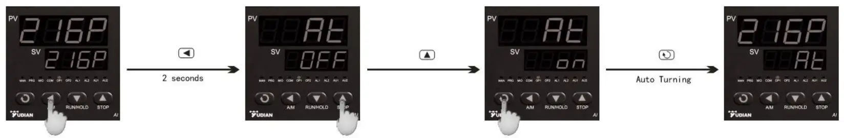
Note1 : If the setpoint is different, the parameters obtained from auto-tuning are possibly different. So you’d better set setpoint to an often-used value or middle value first, and then start auto-tuning.
Depending on the system, the auto-tuning time can be from several seconds to several hours.
Note2: Setting of CHYS may have influence on AT. The lower value of CHYS the higher accuracy. But too low CHYS isn’t advice, CHYS=2.0 is adviced.
Note3: At the beginning after AT, the result maybe not table but it will get best result after a time.
Parameter Setting
In basic display status, press ![]() and hold for about 2 seconds to access the Field Parameter Table. Pressing
and hold for about 2 seconds to access the Field Parameter Table. Pressing ![]() will move to the next parameter; pressing
will move to the next parameter; pressing ![]()
![]() or
or ![]() can modify a parameter. Press and hold can return to the preceding parameter. Press
can modify a parameter. Press and hold can return to the preceding parameter. Press ![]() (don’t release) and then press
(don’t release) and then press ![]() key simultaneously to escape from the parameter table. The instrument will escape automatically from the parameter table if no key is pressed within 30 seconds. Setting Loc=808 and then press
key simultaneously to escape from the parameter table. The instrument will escape automatically from the parameter table if no key is pressed within 30 seconds. Setting Loc=808 and then press ![]() can access System Parameter Table.
can access System Parameter Table.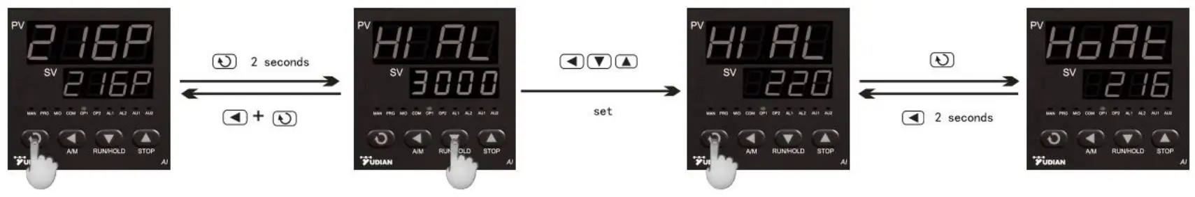
Field parameter table (Press and hold for 2 seconds to access)
| Code | Name | Description | Factory value | ||||||||||||||||||||||||
| HIAL | High limit alarm | Alarm on when PV (Process Value) >HIA; alarm off when PV<HIA-AHY | 3000 | ||||||||||||||||||||||||
| LoAL | Lower limit alarm | Alarm on when PV (Process Value) <LoA; alarm off when PV>LoA-AHY | -999 | ||||||||||||||||||||||||
| HdAL | Deviation high alarm | Alarm on when PV-SV>HdA; alarm off when PV-SV<HdA-AHY | 50 | ||||||||||||||||||||||||
| LdAL | Deviation low alar | m Alarm on when PV-SV<LdA; alarm off when PV-SV>HdA-AHY | -999 | ||||||||||||||||||||||||
| Loc | Parameter Lock | Loc=0: Allowed to modify parameters and do AT Loc=1: Allowed to modify parameters but cannot AT Loc=2: Allowed to modify parameters and AT Loc=4-255: NOT allowed to modify parameters ecept Loc. Loc=808, Set to 808 and press , allowed modify all parameters. | 0 | ||||||||||||||||||||||||
| AHYS | Hysteresis | Avoid wrong frequent alarm caused by wrong value setting | 2 | ||||||||||||||||||||||||
| AoP | Alarm Output assignment | AoP is to define the place of HIAL,LoAL,HdAL alarms like : Value 0~4.0 means never alarm, 3and4 mean alarm from AU1,AU2. E.g. AOP=403 means HIAL alarm from AU1, HdAL from AU2.LoAL no alarm | 0~4444 | ||||||||||||||||||||||||
| CrL | Control mode | onoF : On-off control, used in normal case APld: high precision control PID mode nPld: standard PID control | APId | ||||||||||||||||||||||||
| Srun | Running status | Run, normal running status, PRG light on Stop, stop status, below windo shows “stop”,PRG light out Hold, keep current status, program stop counting time at this moment | stop | ||||||||||||||||||||||||
| Act | Direct/reverse acting function | rE: Reverse acting.Increase in measured variable causes a decrease in the output,such as heating control. dr: Direct acting.Increase in measured variable causes an increase in the output,such as refrigerating control. rEbA: Reverse acting with low limit alarm and deviation low alarm blocking at the beginning of power on. drbA: Direct acting with high limit alarm and deviation high alarm blocking at the beginning of power on. | rE | ||||||||||||||||||||||||
| P | Proportional band | Proportional band in PID with unit℃/F. Notes: normally use At to confirm P,I,D and Ctl .But can set known correct value. | 30 | ||||||||||||||||||||||||
| I | Time of Integral | Time of integral in PID.No integral effect when I=0 unit is 1 second | 100 | ||||||||||||||||||||||||
| d | Time of Derivative | Time of derivative in PID.No derivative effect when d=0. Display unit is 0.1second | 50 | ||||||||||||||||||||||||
| Ctl | Control period | Small value can improve control accuracy. For SSR output, generally 0.5 to 3.0 seconds. For Relay output, generally 15~40 seconds, because small value will cause the frequent On-Off of mechanical switch and shorten its service life. CtI is recommended to be 1/4 ~ 1/10 of derivative time. When control under on-off control,Ctl use as restart delay time affer off,for protect compressor application. | 2.0 or 20 | ||||||||||||||||||||||||
| CHYS | Control Hysteresis | CHY is used for on-off control, if PV > SV, output turns off; PV<SV-CHYS, output turns on. | 2 | ||||||||||||||||||||||||
| InP | Input specification |
| 1 | ||||||||||||||||||||||||
| dPt | Resolution | “0” means 1℃or 1F, “0.0” means 0.1℃/F | 0 | ||||||||||||||||||||||||
| Scb | Input Shift | Scb is used to make input shift to compensate the error produced by sensor or input signal. PV_ after_ compensation= PV_ before_ compensation + Scb. Note: normally set it as 0 | 0 | ||||||||||||||||||||||||
| FILt | PV input filter | The value of FIL will determine the ability of filtering noise. If great interference exists, then you can increase parameter “FIL” gradually to make momentary fluctuation of measured value less than 2 to 5. When the instrument is being metrological verified, “FIL” s can be set to 0 or 1 to shorten the response time. | 1 | ||||||||||||||||||||||||
| Fru | Power frequency and display unit | 50C –frequency 50Hz,display unit ℃. 50F– frequency 50Hz,display unit F. 60C –frequency 50Hz,display unit ℃. 60F– frequency 50Hz,display unit F. | 50C | ||||||||||||||||||||||||
| OPH | Output highest limit | When PV<OEF, max limit 100% | 100 | ||||||||||||||||||||||||
| OEF | OPH valid range | When PV<OEF,OUTP output highest limit is OPH, When PV>OEF, no limit ,100% output Note: if you want to avoid too quick temperature raising, and temperature is lower than 150C, only 30% is allowed for heating power, then you can set: OEF=150.0 ℃, OPH=30% | 3200 | ||||||||||||||||||||||||
| AF | Senior function code | AF=A*1+B*2+E*16+G*64 A=0,HdAL and LdAL is for Hysteresis alarm;A=1,they are absolute alarm B=0,single lop alarm, B=1,Dual loops alarm E=0,HIAL ,LOAL are absolute highest alarm and howest alarm E=1,HIAL,LOAL are hysteresis highest alarm and hysteresis lowest alarm G=0,sensor allow ,. G=1,not allow higher than highest alarm value Set it as 0 unless an expert tells you to change. | 0 | ||||||||||||||||||||||||
| SPL | Lower limit of SV | Mininmum value of SV | 0 | ||||||||||||||||||||||||
| SPH | Upper limit of SV | Maximum value that SV allowed to be. When SPH=400,the SV range will 0~400℃. | 1200 | ||||||||||||||||||||||||
| SPr | Limit of temperature rising speed | If SPr is set as valid, when controller works, RUN light will shine if wrong or unormal speed occurs. | 0 | ||||||||||||||||||||||||
| PonP | Auto running when power on | Cont, controller stop work StoP, when power on, it’s in stop status. Run1, continue working dASt, if now alarm, then work, if alarm, stop working HoLd,(only for AI-518P),if accident short of electricity, stop work. | cont | ||||||||||||||||||||||||
| EP1~E P8 | Senior function code | Can set 1~8 field parameter. If not need or less than 8, can set it as nonE. |
Fault analysis
| Phenomena | Causation | Treatment Method | |
| No power |
|
| |
| SX3 | SV display OraL | Sensor broken | Change the sensor |
| Alarm or Over temperature light on | Machine body higher than the limited temperature, protect now! | The Temperature down to safety temperature and recover by itself (Inspect the reason or change the limited temperature) | |
| Not work | Specification wrong changed | Change the specification | |
| Temperature no rising |
| Contact with the repair | |
Customer Support