HIOKI VT1005 AC-DC High Voltage Divider User Manual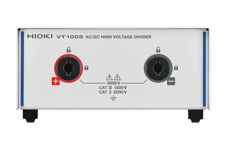
Market Requirements and Issues
Efficiency is an important indicator of performance for power control systems such as inverters. Power analyzers are ideal for measuring efficiency. However, General power analyzers cannot directly measure voltages of greater than 1000 V (AC). Inverters used in applications such as railway and power grids convert high-voltage power, therefore it is necessary to measure voltages above 1000 V to determine the efficiency of these devices.
Silicon carbide (SiC) is attracting attention as a next-generation material that could take the place of conventional silicon (Si). The use of SiC power devices in inverters makes it possible to balance high-speed switching control with highefficiency power conversion. Developers and manufacturers need to be able to measure efficiency accurately on the order of 0.1% to verify the effects of the efficiency improvements in such inverters. In these applications, it is essential to measure the switching frequency (high-frequency) component as well as the fundamental wave contained in the output side voltage.
High voltage differential probes, dividers, or voltage transformers (VT), also called potential transformers (PT) are used when measuring high voltages. However, general dividers and VT or PT have a narrow band and cannot measure highfrequency components. High voltage differential probes have a wide measurement bandwidth and can observe highfrequency components, but their frequency characteristic is not flat, making accurate and repeatable measurement impossible.
The VT1005 Solution
The VT1005 safely measures voltages up to 5000 V, converts them to a lower voltage, and outputs them to a power analyzer. As a result, the device can be used to measure the efficiency of inverters that convert high-voltage power. In addition, the VT1005 can measure the voltage across a band that ranges from DC to 4 MHz with amplitude error of within ±0.1% (from DC to 200 kHz) and phase error within ±0.1°(*1) (from DC to 500 kHz). It measures not only the fundamental wave of the power output from the inverter but also the switching frequency component accurately and with high repeatability
Application
Index
- Evaluation of the Efficiency of Inverters That Use SiC Power Devices in Electrical Railways
- Evaluation of the Efficiency of Inverters That Use SiC Power Devices in Industrial Equipment
- Evaluation of the Efficiency of Solar Inverters That Support High-Voltage Input
- Evaluation of Loss in Transformers and Reactors Designed for Use in High Voltage Circuits
- Evaluation of the Efficiency of Wireless Power Transfer (WPT) Systems
Evaluation of the Efficiency Of Inverters That Use SiC Power Devices In Electrical Railways (Industrial Equipment)
The VT1005 can be used with a power analyzer PW8001 to measure the efficiency of inverters that use SiC power devices.
DUT: Engineers are striving to realize improvements on the order of 0.1% in the efficiency of inverters that use SiC power devices. High-efficiency inverters convert to power using highspeed switching control. Active power on the output side of inverters includes the switching frequency as well as harmonic components of about 10× that frequency.
Measurement: To accurately measure efficiency, it’s essential to measure high-frequency components. The VT1005 can be used to measure a band ranging from DC to 4 MHz. In addition, it can measure amplitude error within 0.1% from DC to 200 kHz.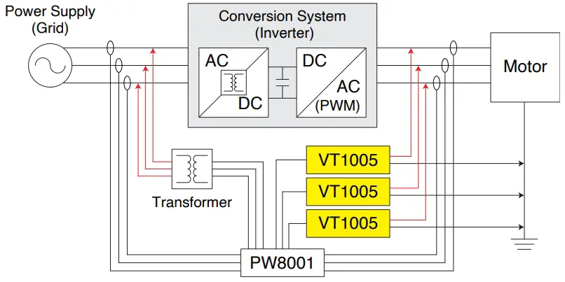
Evaluation of the Efficiency Of Solar Inverters That Support High-Voltage Input
The VT1005 can be used with a power analyzer PW8001 to measure the efficiency of solar inverters that support highvoltage input.
DUT: Energy losses can be reduced by transmitting power at high voltages. Solar inverters with high-voltage input are increasingly being used to improve the efficiency of power generating systems.
Measurement: Power analyzers are ideal for measuring conversion efficiency, but they cannot directly measure high voltages. The VT1005 allows power analyzers to measure voltages of up to 5000 V.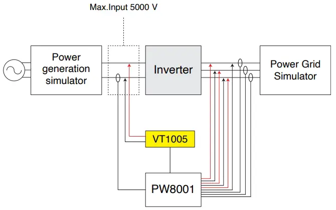
Evaluation of Loss in Transformers and Reactors Designed for Use in High-Voltage Circuits
The VT1005 can be used with a power analyzer PW8001 to measure loss in devices such as reactors and transformers.
DUT: Reactors and transformers are low power factor loads. Measurement: When the power factor is low, phase error causes measurement error to increase. The VT1005 has defined phase correction values. Phase correction can be performed by the power analyzer to allow measurement with a phase error of within ±0.1° from DC to 500 kHz.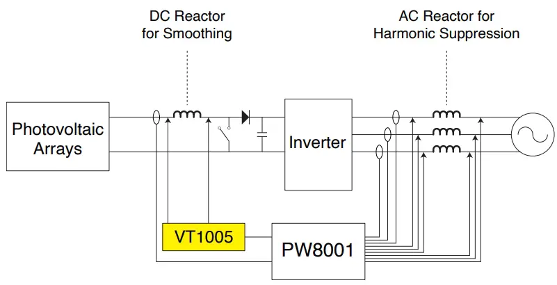
Evaluation of the Efficiency Of Wireless Power Transfer (WPT) Systems
The VT1005 can be used with a power analyzer PW8001 to measure the efficiency of wireless power transfer (WPT) systems.
DUT: Because they use a coil to transmit power, wireless power transfer (WPT) systems have transmission and reception components that operate at extremely low power factor values.
Measurement: When the power factor is low, phase error causes measurement error to increase. The VT1005 has defined phase correction values. Phase correction can be performed by the power analyzer to allow measurement with a phase error of within ±0.1° from DC to 500 kHz.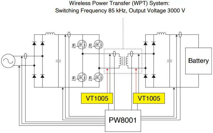
Specification
Index
- Max. Input 5000 V (*1), 2000 V CAT II , 1500 V CAT III
- Measurement Accuracy: ±0.08% (DC), ±0.04% (50/60 Hz), ±0.17% (50 kHz)
- Frequency Flatness: ±0.1% Amplitude Band 200 kHz Typical, ±0.1° Phase Band 500 kHz Typical (*2)
- Measurement Band: DC to 4 MHz (-3 dB)
- Noise Resistance: CMRR 80 dB Typical (100 kHz), Differential Input Method
*1: ±7100 Vpeak, anticipated transient over voltage of 0 V
*2: After phase correction by the power analyzer
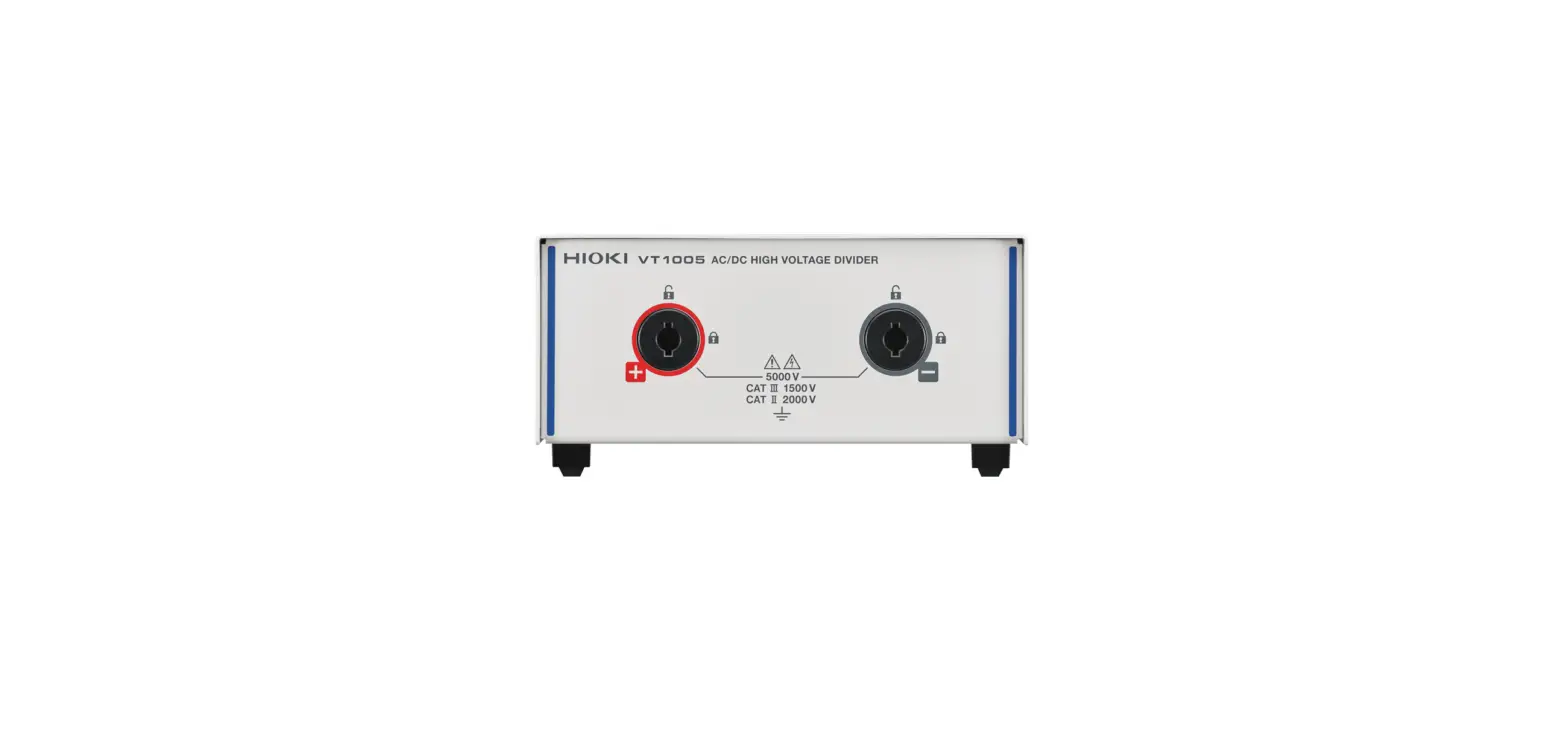
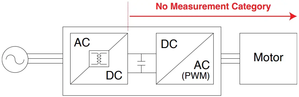
Max. Input 5000 V (*1), 2000 V CAT II , 1500 V CAT III
Measure voltages of up to 5000 Vrms (*1), 2000 Vrms CAT II, or 1500 Vrms CAT III. Measured voltages are divided (1000:1) and output to the power analyzer.
*1: ±7100 V peak, no measurement category, anticipated transient over voltage of 0 V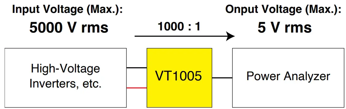
Max. Rated Voltage | 5000 Vrms, ±7100 Vpeak |
| Measurement Category | 5000 Vrms (*1) |
*1: ±7100 Vpeak, no measurement category, anticipated transient
over voltage of 0 V
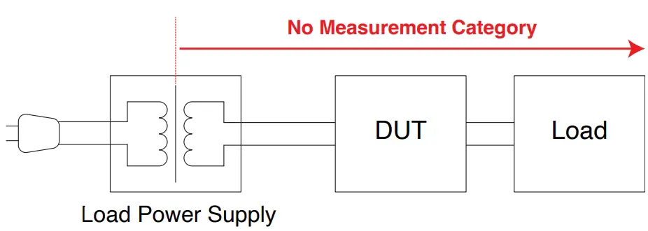
The power supply is internally isolated, for example, load power supplies used in testing. Power supply and DUT are not connected directly.
The secondary side of location isolated inside the DUT
Measurement Accuracy: ±0.08% (DC), ±0.04% (50/60 Hz), ±0.17% (50 kHz) Frequency Flatness: ±0.1% Amplitude Band 200 kHz Typical, ±0.1° Phase Band 500 kHz Typical (*1)
The VT1005 can measure voltage with excellent accuracy across a broad band of frequencies. Accuracy is 0.1% or less at DC and commercial frequencies (50/60 Hz). In addition, the device can measure the most commonly used switching frequencies (10 kHz or less) and the switching frequencies of inverters that use SiC power devices (from 10 kHz to 50 kHz) with a high degree of accuracy. *1: After phase correction by the power analyzer
| Frequency | Amplitude Accuracy ±(% of reading + % of full scale) | Phase Accuracy |
| DC | ±0.03% ±0.05% | – |
| DC < f < 30 Hz | ±0.2% ±0.1% | ±0.1° |
| 30 Hz ≤ f < 45 Hz | ±0.1% ±0.1% | ±0.1° |
| 45 Hz ≤ f ≤ 66 Hz | ±0.02% ±0.02% | ±0.06° |
| 66 Hz < f ≤ 100 Hz | ±0.1% ±0.02% | ±0.12° |
| 100 Hz < f ≤ 1 kHz | ±0.1% ±0.02% | ±0.2° |
| 1 kHz < f ≤ 5 kHz | ±0.15% ±0.02% | ±0.4° |
| 5 kHz < f ≤ 50 kHz | ±0.15% ±0.02% | ±(0.08° × f kHz)° |
| 50 kHz < f ≤ 100 kHz | ±0.5% ±0.02% | ±(0.08° × f kHz)° |
| 100 kHz < f ≤ 300 kHz | ±1.5% ±0.5% | ±(0.08° × f kHz)° |
| 300 kHz < f ≤ 1 MHz | ±5.0% ±0.5% | ±(0.08° × f kHz)° |
| Frequency Bandwidth | 4 MHz (-3 dB Typical) | |
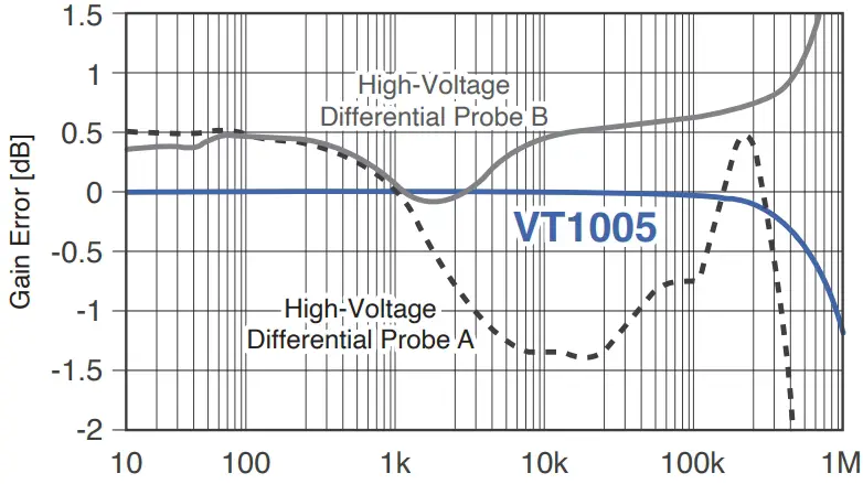
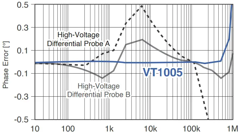
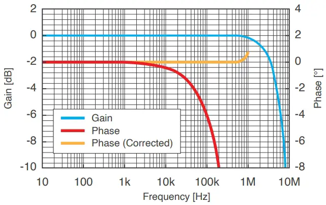
Frequency Flatness Is the Key in Efficiency and Loss Measurement Even if an instrument has a wide measurement band, it will be unable to accurately measure the efficiency of high-efficiency inverters or loss in reactors if it has high amplitude error and phase error. The VT1005 delivers amplitude error of within ±0.1% (from DC to 200 kHz) and phase error of within ±0.1° (*1) (from DC to 500 kHz). The Excellent frequency flatness enables accurate measurement of inverter efficiency to the nearest 0.1%. In addition, it can measure loss in reactors that have a voltage and current phase difference of 88° with an error of ±5%. *1: After phase correction by the power analyzer
Comparison of High-Voltage Differential Probe and VT1005
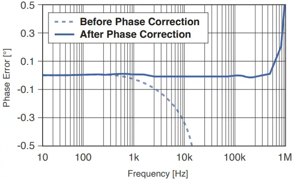
Phase Correction With Power Analyzer
The VT1005 has defined phase correction values. These correction values can be entered into Hioki power analyzers to allow correction of phase error, which makes it possible to accurately measure voltage in the high frequency band.
At Low Power Factors, Phase Error Has a Substantial Impact on Power Error
Power Ratio ≈ 1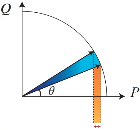
Power Ratio ≈ 0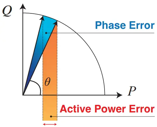
Measurement Band: DC to 4 MHz (-3 dB)
The VT1005’s measurement band is DC to 4 MHz, allowing it to measure voltage from DC to high frequencies.
Active Power Spectrogram for an Inverter’s Output Power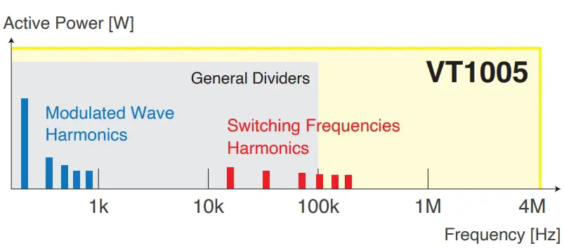
Noise Resistance: CMRR 80 dB Typical (100 kHz), Differential Input Method
The VT1005 is highly resistant to both common-mode and high-frequency noise, allowing it to measure voltage accurately even in noisy environments. Since conversion devices like inverters are sources of noise, noise resistance is important in efficiency evaluation.
Differential Input Method:
Outputs Potential Difference Between (+) And (-) Signals Common-Mode Noise Is Canceled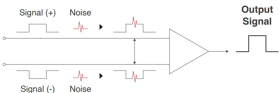
Observation of a voltage that does not exist, leading to a significant measurement error
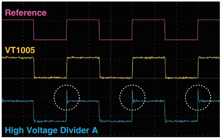
Comparing the noise resistance measurement result of an inverter’s secondary side.
SiC power devices are characterized by fast voltage rising and falling response, and their output wave forms contain numerous high-frequency components. Some companies’ dividers are prone to the effects of high-frequency noise outside the band. Use of such dividers can lead to erroneous observation of significant ringing that is not actually occurring, resulting in large measurement errors
| Maximum rated voltage | 5000 Vrms, ±7100 Vpeak (Provided this falls within the frequency derating curve illustrated) |
| Maximum rated voltage(line-to-ground) | No measurement category: 5000 V AC/DC, ±7100 V peak, Anticipated transient over voltage: 0 V Measurement category II: 2000 V AC/DC, anticipated transient over voltage: 12000 V Measurement category III: 1500 V AC/DC, anticipated transient over voltage: 10000 V |
| Measurement accuracy | ±0.08% (DC), ±0.04% (50/60 Hz), ±0.17% (50 kHz) |
| Frequency flatness | Band where amplitude falls within ±0.1% range: 200 kHz (typical)Band where phase falls within ±0.1° range: 500 kHz (typical, after phase delay corrected) |
| Measurement bandwidth | DC to 4 MHz (Amplitude and phase accuracy specified up to 1 MHz) |
| Voltage dividing ratio Common-mode voltage rejection ratio (CMRR) | 1000 : 1 |
| 50/60 Hz: 90 dB (Typical), 100 kHz: 80 dB (Typical) | |
| Operating temperature and humidity range | −10°C to 50°C (14°F to 122°F), 80% RH or less (non-condensing) |
| Standards | Safety: EN 61010, EMC: EN 61326 Class A |
| Power supply | 100 V to 240 V AC (50/60 Hz) |
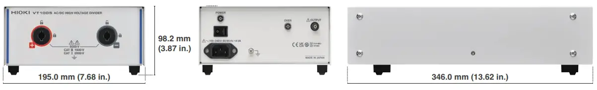
| Dimensions (W x H x D) | Approx. 195.0 × 83.2 × 346.0 mm (7.68 × 3.28 × 13.62 in.) |
| Weight | Approx. 2.2 kg (77.6 oz.) |
| Measurement method | Differential input |
| Accessories | • L1050-01 Voltage Cord (1.6 m/5.25 ft)• L9217 Connection Cord (insulated BNC, 1.6 m/5.25 ft)• 9704 Conversion Adapter (insulated-female BNC-to-banana plug)• Power cord |
Frequency derating curve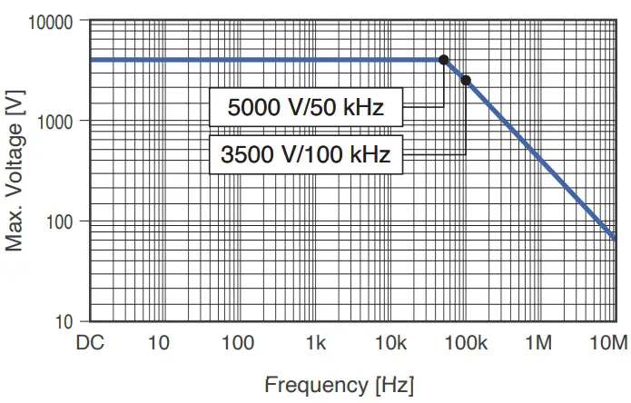
Measurement accuracy
| Frequency | Amplitude Accuracy ±(% of reading + % of full scale | Phase Accuracy |
| DC | ±0.03% ±0.05% | – |
| DC < f < 30 Hz | ±0.2% ±0.1% | ±0.1° |
| 30 Hz ≤ f < 45 Hz | ±0.1% ±0.1% | ±0.1° |
| 45 Hz ≤ f ≤ 66 Hz | ±0.02% ±0.02% | ±0.06° |
| 66 Hz < f ≤ 100 Hz | ±0.1% ±0.02% | ±0.12° |
| 100 Hz < f ≤ 1 kHz | ±0.1% ±0.02% | ±0.2° |
| 1 kHz < f ≤ 5 kHz | ±0.15% ±0.02% | ±0.4° |
| 5 kHz < f ≤ 50 kHz | ±0.15% ±0.02% | ±(0.08° × f kHz)° |
| 50 kHz < f ≤ 100 kHz | ±0.5% ±0.02% | ±(0.08° × f kHz)° |
| 100 kHz < f ≤ 300 kHz | ±1.5% ±0.5% | ±(0.08° × f kHz)° |
| 300 kHz < f ≤ 1 MHz | ±5.0% ±0.5% | ±(0.08° × f kHz)° |
| Frequency Bandwidth | 4 MHz (-3 dB Typical) | |
VT1005 Appearance
VT1005 Options
 | 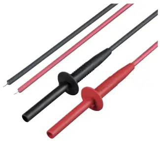 | 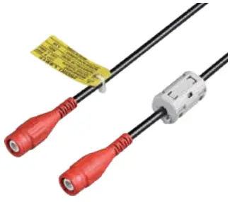 | 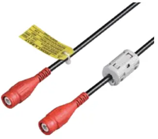 |  | 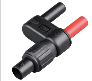 |
| L1050-01 | L1050-03 | L9217 | L9217-01 | L9217-02 | 9704 |
| Voltage Cord 1.6 m (5.25 ft) | Voltage Cord 3.0 m (9.84 ft) | Connection Cord (insulated BNC) 1.6 m (5.25 ft) | Connection Cord (insulated BNC) 3.0 m (9.84 ft) | Connection Cord (insulated BNC) 10 m (32.81 ft) | Conversion Adapter BNC-to-banana plug |


