
![]() DB2-2x Product Developers Tool Kit
DB2-2x Product Developers Tool Kit
User Manual
Fast-tracking design and implementation of Myriota-enabled IoT solutions.
Get up and running in minutes on the Myriota Network with our Development Board, which comes equipped with antennas, GNSS, battery, and sensor interface breakouts.
The Myriota Development Board is a key part of the developer tools platform for the Myriota Module. Combined with the Myriota Software Development Kit (SDK) and Application Programming Interface (API), the board allows you to get familiar with the behavior and performance of the Network, and prototype any type of application you can imagine for remote IoT.
Network Ready
The Development Board has a Myriota Module onboard, providing access to our low-cost, low bandwidth, a direct-to-orbit satellite network.
Myriota SDK
The Myriota Software Development Kit (SDK) provides tools, code samples, and documentation to help you build your Myriota-enabled product as quickly as possible.
Application Programming Interface (API)
The Myriota API provides job scheduling, sensor input/output, diagnostics, access to Myriota’s communication stack, and more.
Developer Site
The Myriota Developer Site (developer.myriota.com) is a one-stop shop for the most up-to-date technical guides, tutorials, API documentation and example code for using the Developer Board to its greatest potential.
Revision History
| Rev | Date | Description of Change |
| 1 | Mar-20 | Initial version |
| 1.1 | Mar-20 | Added missing board image. Updated link to technical documentation |
| 1.2 | Jul-20 | Updated availability date for DB2-2x. Updated various links |
| 1.3 | Jan-21 | Updated with information for V2 |
Find the latest versions of all Myriota documentation at developer.myriota.com
How to Contact Us
| Technical Support developer.myriota.com [email protected] | Sales Support [email protected] | Myriota Online myriota.com |
Disclaimer
The information contained in this document (collectively, the “Information”) is provided to you (both the individual receiving this document and any legal entity on behalf of which such individual is acting) (“You” and “Your”) by Myriota Pty Ltd for information purposes only.
- Information in this document is provided solely to enable system and software implementers to use Myriota Pty Ltd products.
- Myriota Pty Ltd reserves the right to make changes without further notice to any products herein.
- You are responsible for making Your own assessments concerning the Information and Myriota recommends that You assess the accuracy, completeness, and relevance of the Information for Your purposes before using or relying on any of the Information.
- Myriota is providing the Information to you “AS IS” and without regard to Your specific requirements.
- Myriota has exercised reasonable care in preparing the Information, however, Myriota does not warrant the accuracy, completeness, or relevance of the Information and accepts no liability for any errors or omissions in the Information.
- You acknowledge and agree that Your use of the Information is at your sole risk and that to the extent permitted by law Myriota is not liable for any loss or damage of whatever nature (direct, indirect, consequential, or other) that arises in any way from Your use of or reliance on the Information.
- For further information, see developer.myriota.com or contact your Myriota sales representative.
Safety and Compliance
FCC Compliance Information
This equipment has been tested and found to comply with part 15 of the FCC Rules. Operation is subject to the following two conditions:
- This device may not cause harmful interference, and
- This device must accept any interference received, including interference that may cause undesired operation
This equipment has been tested and found to comply with the limits for a Class B digital device, pursuant to part 15 of the FCC Rules. These limits are designed to provide reasonable protection against harmful interference in a residential installation. This equipment generates uses and can radiate radio frequency energy and, if not installed and used in accordance with the instructions, may cause harmful interference to radio communications.
However, there is no guarantee that interference will not occur in a particular installation. If this equipment does cause harmful interference to radio or television reception, which can be determined by turning the equipment off and on, the user is encouraged to try to correct the interference by one or more of the following measures:
- Reorient or relocate the receiving antenna.
- Increase the separation between the equipment and receiver.
- Connect the equipment into an outlet on a circuit different from that to which the receiver is connected.
- Consult the dealer or an experienced radio/TV technician for help.
WARNING: Changes or modifications not expressly approved by Myriota may render the device non-compliant to FCC and other regulatory body standards for operation and may void the user’s authority to operate the equipment.
Operation under the provisions of this section is restricted to devices that use radiofrequency energy to identify the contents of commercial shipping containers. Operations must be limited to commercial and industrial areas such as ports, rail terminals, and warehouses.
Two-way operation is permitted to interrogate and load data into devices. Devices operated pursuant to the provisions of this section shall not be used for voice communications.
To prevent interference to Federal Government radar systems, operation under the provisions of this section is not permitted within 40 kilometers of the following locations:
RF Exposure Warning Statement: In accordance with 47 CFR §2.1091 and Canada’s Health Safety Code 6, this device shall be installed to provide a separation distance of 32cm (12.6”) between the antenna and any persons.
| DoD Radar Site | Latitude | Longitude |
| Beale Air Force Base | 39°08′10″ N | 121°21′04″ W |
| Cape Cod Air Force Statio | 41°45′07″ N | 070°32′17″ W |
| Clear Air Force Station | 64°55′16″ N | 143°05′02″ W |
| Cavalier Air Force Station | 48°43′12″ N | 097°54′00″ W |
| Eglin Air Force Base | 30°43′12″ N | 086°12′36″ W |
ISED Compliance Information
This device complies with Industry Canada’s license-exempt RSS. Operation is subject to the following two conditions:
- This device may not cause interference; and
- This device must accept any interference, including interference that may cause undesired operation of the device.
RF Exposure Compliance Information
This equipment complies with the FCC §2.1091 and ISED RSS-102 RF Exposure Limits. A minimum of 13 centimeters (5 inches) separation between the device and the user and all other persons should be maintained.
Variants
| Part Number | Band | Frequency (MHz) |
| DB2-2x | UHF TX UHF RX | 399.9 – 400.05 400.15 – 401 |
System Overview
Global Navigation Satellite System (GNSS)
- SAM-M8Q-0-10 GNSS module
- GPS and GLONASS
- Acquisition Time 1s (hot start) or 30s (cold start)
- Accuracy 2.5m CEP 50% (24 hours static, good sky view)
- Sensitivity -164 dBm (tracking)
Connectors (common to V1 and V2)
- Power ON/OFF header (J200)
- GNSS backup power supply header (J500)
- Onboard GNSS antennas
- MMCX connector for external VHF/UHF antenna (J503)
- 2 x AA battery holders (BH200)
- Micro USB (J403)
- 2×17 pin male 100mil (2.54mm) pitch
- Breakout Header (J401)
Connectors (V1 only)
- Onboard ISM antenna for lab testing with the Satellite Simulator (AN501)
Connectors (V2 only)
- SMA antenna connector (J501)
- MMCX surface mount connectors for RF testing (J502 and J505)
Power
- Battery 3V to 3.6V
- USB
Programming
- Serial port via micro USB or SWD
Environmental
- Operating temperature -30ºC to +70ºC
- RoHS compliant
Buttons
- RESET (SW300)
- WAKE UP (SW301)
Dimensions
- 130mm X 90mm x 200mm (height with antenna)
Top Botton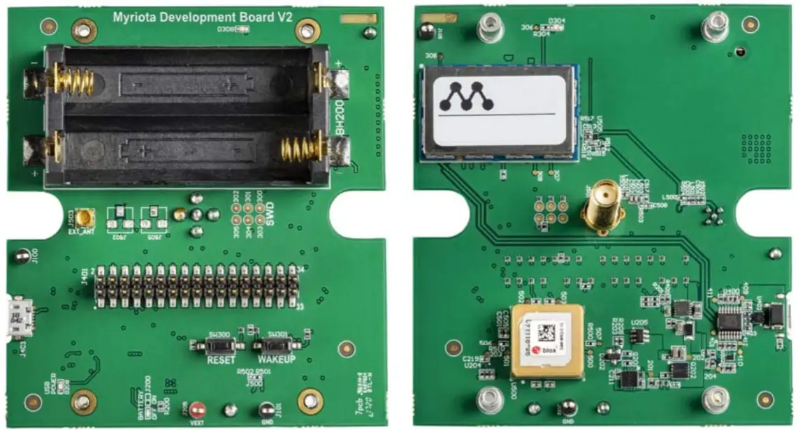
Breakout Header Pins
Breakout header J401 breaks out some of the module pins
| Header Pin | Module Pin | Note |
| Number | Name | |
| 1 | VEXT | |
| 2 | VUSB | |
| 3 | I2C_SDA | |
| 4 | UART0_CTS | |
| 5 | I2C_SCL | |
| 6 | GND | |
| 7 | ADC0 | Two 10k ohm divider resistors to double the input voltage range |
| 8 | UART0_TX | |
| 9 | GND | |
| 10 | UART0_RX | |
| 11 | ADC1 | Two 10k ohm divider resistors to double the input voltage range |
| 12 | UART0_RTS | |
| 13 | GPIO7 | |
| 14 | NRST | |
| 15 | GPIO8 | |
| 16 | SWCLK | |
| 17 | VIO_REF | |
| 18 | SWDIO | |
| 19 | SPI_MOSI | |
| 20 | GND | |
| 21 | SPI_MISO | |
| 22 | GPIO1_WKUP | |
| 23 | SPI_SCK | |
| 24 | SPI_CS | |
| 25 | GND | |
| 26 | LEUART_TX | |
| 27 | GPIO0_WKUP | |
| 28 | LEUART_RX | |
| 29 | UART1_TX | |
| 30 | PULSE0 | |
| 31 | UART1_RX | |
| 32 | PULSE1 | |
| 33 | RF_TEST2 | |
| 34 | RF_TEST1 |
How to Contact Us
| Technical Support developer.myriota.com [email protected] | Sales Support [email protected] | Myriota Online myriota.com |
developer.myriota.com
MYRIOTA-TEC-187


