
EVCO EV3H94 Controller for DHW Heat Pump Heaters

OVERVIEW
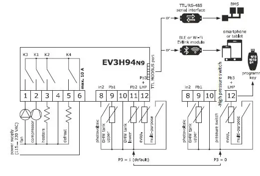
- power supply 115… 230 VAC
- DHW tank upper and lower probe, evaporator probe (PTC/NTC/Pt 1000)
- photovoltaic, HP, and multi-purpose digital input (see i0)
- compressor relay 16 A res. @ 250 VAC
- alarm buzzer
- TTL MODBUS slave port for EVconnect app, Epoca remote monitoring system or for BMS.
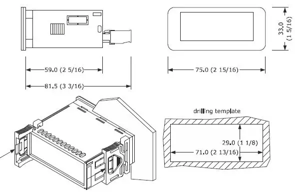
MEASUREMENTS AND INSTALLATION
Measurements in mm (inches). To be fitted to a panel, snap-in brackets provided.
INSTALLATION PRECAUTIONS
- the thickness of the panel must be between 0.8 and 2.0 mm (1/32 and 1/16 in);
- ensure that the working conditions are within the limits stated in the TECHNICAL SPECIFICATIONS section;
- do not install the device close to heat sources, equipment with a strong magnetic field, in places subject to direct sunlight, rain, dampness, excessive dust, mechanical vibrations, or shocks;
- in compliance with safety regulations, the device must be installed properly to ensure adequate protection from contact with electrical parts. All protective parts must be fixed in such a way as to need the aid of a tool to remove them.
ELECTRICAL CONNECTION
- use cables of an adequate section for the current running through them.
- to reduce any electromagnetic interference locate the power cables as far away as possible from the signal cables.
PRECAUTIONS FOR ELECTRICAL CONNECTION
- if using an electrical or pneumatic screwdriver, adjust the tightening torque;
- if the device is moved from a cold to a warm place, humidity may cause condensation to form inside. Wait for about an hour before switching on the power;
- make sure that the supply voltage, electrical frequency and power are within the set limits. See the section TECHNICAL SPECIFICATIONS;
- disconnect the power supply before carrying out any type of maintenance;
- do not use the device as a safety device;
- for repairs and for further information, contact the EVCO sales network.
FIRST-TIME USE
- Carry out the installation following the instructions given in the section MEASUREMENTS AND INSTALLATION.
- Power up the device as set out in the section ELECTRICAL CONNECTION: an internal test will startup.
- The test normally takes a few seconds; when it is finished the display will switch off.
- Configure the device as shown in the section Setting configuration parameters. Recommended configuration parameters for first-time use:
| PAR. | DEF. | PARAMETER | MIN… MAX. |
| SP1 | 55.0 | setpoint in economy mode | r3… r4 |
| SP2 | 65.0 | setpoint in comfort mode | r1… r2 |
| P0 | 1 | type of probe | 0 = PTC 1 = NTC 2 = Pt 1000 |
| P2 | 0 | temperature measurement unit | 0 = °C 1 = °F |
| P3 | 1 | enabled probes | 0 = DHW tank upper probe + high pressure input 1 = DHW tank upper and lower probe |
| d1 | 2 | type of defrost | 0 = electric 1 = hot gas 2 = compressor stopped 3 = hot gas balancing the pressure |
Then check that the remaining settings are appropriate; see the section CONFIGURATION PARAMETERS.
- Disconnect the device from the mains.
- Make the electrical connection as shown in the section ELECTRICAL CONNECTION without powering up the device.
- For the connection in an RS-485 network connect the interface EVIF22TSX or EVIF23TSX, to activate real-time functions connect the module EVIF23TSX, to use the device with the EPoCA remote monitoring system, connect the EVIF25TWX module, to use the device with the APP EVconnect connect the interface EVIF25TBX; see the relevant instruction sheets. If EVIF22TSX or EVIF23TSX is used, set parameter bLE to 0.
- Power up the device.
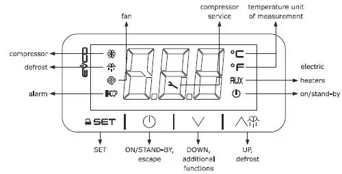
USER INTERFACE AND MAIN FUNCTIONS
Switching the device on/off
- `If the device is switched on, the display will show the P5 value (“DHW tank upper temperature” default); if the display shows an alarm code, see the section ALARMS.
| LED | ON | OFF | FLASHING |
| compressor switched on | compressor switched off | – compressor protection active – setpoint being set | |
| defrost active | – | – | |
| fans switched on | fans switched off | – | |
| HACCP | alarm active | – | – |
| compressor mainte- nance request | – | operation with EVconnect APP ac- tive | |
| °C/°F | temperature display | – | – |
| AUX | heaters switched on | heaters switched off | – |
| device switched off | device switched on | – |
EVCO S.p.A. | EV3H94 | Instruction sheet ver. 1.0 | Code 1043H94E104 | Page 2 of 6 | PT 05/21
Unlocking the keypad
Touch a key for 1 s: the display will show the label “URL”.
Setting the setpoint Economy
Check that the keypad is not locked.
| 1. | Touch the SET key: the display will show the label “SP1”. | |
| 2. | Touch the SET key. | |
| 3. | Touch the UP or DOWN keys within 15s to set the value within the limits r3 and r4 (default “40… 55”). | |
| 4. | Touch the SET key (or take no action for 15s). | |
| 5. | Touch the ON/STAND-BY key. |
Setting the Comfort setpoint
Check that the keypad is not locked.
| 1. | Touch the SET key: the display will show the label “SP1”. | |
| 2. | Touch the UP or DOWN key to select the label “SP2”. | |
| 3. | Touch the SET key. | |
| 4. | Touch the UP or DOWN keys within 15s to set the value within the limits r1 and r2 (default “40… 70”). | |
| 5. | Touch the SET key (or take no action for 15s). | |
| 6. | Touch the ON/STAND-BY key. |
Setting the over post activation threshold
Check that the keypad is not locked
| 1. | Touch the SET key: the display will show the label “SP1”. | |
| 2. | Touch the UP or DOWN key to select the label “SP3”. | |
| 3. | Touch the SET key. | |
| 4. | Touch the UP or DOWN keys within 15s to set the value within the limits 10 and r2 (default “10… 70”). | |
| 5. | Touch the SET key (or take no action for 15s). | |
| 6. | Touch the ON/STAND-BY key. |
Activating manual defrost
Check that the keypad isn’t locked and that the anti-legionella and over-boost functions aren’t active.
Touch the UP key for 4s. If P4 = 1 or 2 (default), defrost is activated provided that the evaporator temperature is lower than the d2 threshold.
Silencing the alarm buzzer (if u9 = 1)
Touch a key.
FUNCTIONS AND LOAD OPERATIONS
Economy
- the compressor on if DHW tank lower temperature < “SP1 setpoint – r0 differential” and off if DHW tank lower temperature > “SP1 setpoint”
- fans on if compressor on
- heaters switched off in normal operation (on if needed during defrosting)
Comfort
- the compressor on if DHW tank lower temperature < “SP5 setpoint – r0 differential” and off if DHW tank lower temperature > “SP5 setpoint”
- fans on if compressor on
- heaters on, with a single probe configured (P3 = 0), if DHW tank upper temperature < “SP2 – r6 threshold – r7 differential” and off if DHW tank upper temperature > “SP2 – r6 threshold”.
- heaters on, with two probes configured (P3 = 1), if DHW tank upper temperature < “SP2 – r0 differential” and off if DHW tank upper temperature > “SP2”.
Anti-legionella
It activates at “H0 intervals” or at “Ant time”, provided that DHW tank lower temperature > “SP1 setpoint” and > “SP2 setpoint”
- compressor switched off
- fans switched off
- heaters switched on until DHW tank upper temperature > “H1 threshold” and then for “H3 time”.
Overboost
- It activates in manual mode, provided that DHW tank upper and lower temperature < “SP3 threshold”
- compressor, fans and heaters on until DHW tank upper temperature > “SP1 setpoint”.
Defrosting
It activates with evaporator temperature < “d17 threshold” for “d18 time” or in manual mode, provided that the anti-legionella and over-boost functions are not active
- compressor switched on if d1 = 1
- defrost relay active if d1 = 1 or 2
- fans switched on if d1 = 2
- heaters switched on to prevent too high-temperature drop in the storage tank
Photovoltaic system
- It activates with photovoltaic input active
- operation as in comfort mode, except for “SP2 setpoint” which becomes “SP6 setpoint”.
Green
- It activates with multi-purpose input active and DHW tank upper and lower temperature > “SP8 setpoint”
- compressor switched off
- fans switched off
- heaters switched off.
Antifreeze
- This function is used to prevent water freezing. It is activated when tank upper temperature < “SP7 setpoint” – “r0 differential” and this function is deactivated when tank upper temperature > “SP7 setpoint”
- heaters are switched on.
- This function can be activated only if the controller is on standby.
Pre-opening hot gas defrost valve
- This function is used to balance the pressure at the compressor start-up, and it is activated only if “d1” = 3.
- This function switch on the defrost output “i11” seconds before the start-up of the compressor, this occurs every time the compressor started, even if there is no defrost request.
5.10 Fan operation
- The fan operates depending on the active function, normally C12 seconds before the switch-on of the compressor. There are some exceptions:
- defrost: in the case of hot gas (d1=1) compressor is active but the fan is off. In case of com-pressor stop (d1=2), the compressor is off but fan is active
- alarms: in case of LHP compressor is off but fan is active.
ADDITIONAL FUNCTIONS
Activating/deactivating comfort operation in manual mode
| 1. | Touch the DOWN key for 1 s: the display will show a code. | ||
| 2. | Touch the UP or DOWN key within 15s to select a label. | ||
| COD. | DESCRIPTION | ||
| Auto | activates comfort operation | ||
| ECO | deactivates comfort operation | ||
| 3. | Touch the SET key. | ||
| 4. | Touch the ON/STAND-BY key (or take no action for 60s) to exit the procedure. | ||
Activating the overboost function
| 1. | Touch the DOWN key for 1 s: the display will show a code. | |
| 2. | Touch the UP or DOWN key within 15s to select “ObS”. | |
| 3. | Touch the SET key. | |
| 4. | Touch the ON/STAND-BY key (or take no action for 60s) to exit the procedure. |
Displaying the operating mode
| 1. |
| Touch the DOWN key: the display will show a code. | |
| COD. | DESCRIPTION | ||
| ECO | economy | ||
| ObS | overboost | ||
| Auto | comfort | ||
| Anti | anti-legionella; if flashing, DHW tank lower temperature > “SP1 setpoint” and > “SP2 setpoint” | ||
| dEFr | defrost | ||
| in2 | photovoltaic function | ||
| 2. |
| Touch the ON/STAND-BY key (or take no action for 60s) to exit the procedure. | |
Displaying/deleting compressor functioning hours
| 1. |
| Touch the DOWN key for 1 s: the display will show a code. | |
| 2. | Touch the UP or DOWN key within 15s to select a label. | ||
| COD. | DESCRIPTION | ||
| CH | display compressor working hours in hundreds | ||
| rCH | delete compressor working hours | ||
| 3. |
| Touch the SET key. | |
| 4. | Touch the UP or DOWN key to set “149” (to select rCH). | ||
| 5. |
| Touch the SET key. | |
| 6. |
| Touch the ON/STAND-BY key (or take no action for 60s) to exit the procedure. | |
SETTINGS
| 1. |
| Touch the SET key for 4 s: the display will show the label “PA”. | ||
| 2. |
| Touch the SET key. | ||
| 3. | Touch the UP or DOWN key within 15s to set -19”. | |||
| 4. |
| Touch the SET key (or take no action for 15s): the display will show the label “SP”. | ||
| 5. | Touch the UP or DOWN key to select a parameter. | |||
| 6. |
| Touch the SET key. | ||
| 7. | Touch the UP or DOWN key within 15s to set the value. | |||
| 8. |
| Touch the SET key (or take no action for 15s). | ||
| 9. | Touch the SET key for 4s (or take no action for 60s) to exit the procedure. | |||
Set the date, time and day of the week (if module EVIF23TSX, EVIF25TWX or interface EVIF25TBX is connected)
- Do not disconnect the device from the mains within two minutes since the setting of the time and day of the week.
- if the device communicates with the connect app, the date, time, and day of the week will be automatically set by the smartphone or tablet.
| 1. |
| Touch the UP key. | |
| 2. | Touch the UP or DOWN key within 15s to select the label “rtc”. | ||
| 3. |
| Touch the SET key: the display will show the label “yy” followed by the last two figures of the year. | |
| 4. | Touch the UP or DOWN key within 15 s to set the year. | ||
| 5. | Repeat actions 3. and 4. to set the next labels. | ||
| LAB. | DESCRIPTION OF THE NUMBERS FOLLOWING THE LABEL | ||
| n | month (01… 12) | ||
| d | day (01… 31) | ||
| h | time (00… 23) | ||
| n | minute (00… 59) | ||
| 6. |
| Touch the SET key: the display will show the label for the day of the week. | |
| 7. | Touch the UP or DOWN key within 15 s to set the day of the week. | ||
| LAB. | DESCRIPTION | ||
| Mon | Monday | ||
| tuE | Tuesday | ||
| UEd | Wednesday | ||
| thu | Thursday | ||
| Fri | Friday | ||
| Sat | Saturday | ||
| Sun | Sunday | ||
| 8. |
| Touch the SET key: the device will exit the procedure. | |
| 9. |
| Touch the ON/STAND-BY key to exit the procedure beforehand. | |
Restoring factory settings (default)
- check that the factory settings are appropriate; see the section CONFIGURATION PARAMETERS.
| 1. |
| Touch the SET key for 4 s: the display will show the label “PA”. |
| 2. |
| Touch the SET key. |
| 3. | Touch the UP or DOWN key within 15s to set “149”. | |
| 4. |
| Touch the SET key (or take no action for 15s): the display will show the label “dEF”. |
| 5. |
| Touch the SET key. |
| 6. | Touch the UP or DOWN key within 15s to set “1”. | |
| 7. |
| Touch the SET key (or take no action for 15 s): the display will show “– – –” flashing for 4 s, after which the device will exit the procedure. |
| 8. | Disconnect the device from the power supply. | |
| 9. |
| Touch the SET key for 1s before action 6 to exit the procedure beforehand. |
CONFIGURATION PARAMETERS
|
| No. | PAR. | DEF. | SETPOINT | MIN… MAX. | ||||||
| 1 | SP1 | 55.0 | setpoint in economy mode | r3… r4 | |||||||
| 2 | SP2 | 65.0 | setpoint in comfort mode | r1… r2 | |||||||
| 3 | SP3 | 45.0 | overboost activation threshold | 10 °C/°F… r2 | |||||||
| 4 | SP5 | 55.0 | heat pump switch-off threshold | r1… SP2 | |||||||
| 5 | SP6 | 75.0 | photovoltaic system setpoint | 40… 100 °C/°F | |||||||
| 6 | SP7 | 5.0 | setpoint in antifreeze mode | 0… 40 °C/°F | |||||||
| 7 | SP8 | 40.0 | setpoint in green mode | 0… 100 °C/°F | |||||||
| 8 | SP9 | -7.0 | cold evaporator alarm threshold | -25… 25 °C/°F | |||||||
| 9 | SPA | -25 | evaporator failure alarm thresh- old | -50… 25 °C/°F | |||||||
|
| No. | PAR. | DEF. | ANALOGUE INPUTS | MIN… MAX. | ||||||
| 10 | CA1 | 0.0 | DHW tank upper probe offset | -25… 25 °C/°F | |||||||
| 11 | CA2 | 0.0 | DHW tank lower probe offset | -25… 25 °C/°F | |||||||
| 12 | CA3 | 0.0 | evaporator probe offset | -25… 25 °C/°F | |||||||
| 13 | P0 | 1 | type of probe | 0 = PTC 2 = Pt 1000 | 1 = NTC | ||||||
| 14 | P1 | 1 | enable decimal point °C | 0 = no | 1 = yes | ||||||
| 15 | P2 | 0 | temperature measurement unit | 0 = °C | 1 = °F | ||||||
| 16 | P3 | 1 | enabled probes | 0 = DHW tank upper probe + high pressure input 1 = DHW tank upper and lower probe | |||||||
| 17 | P4 | 2 | evaporator probe function | 0 = disabled (defrost every d18 minutes) 1 = defrost activation and defrost end 2 = defrost activation | |||||||
| 18 | P5 | 0 | value displayed | 0 = DHW tank upper tem- perature 1 = setpoint in comfort mode 2 = DHW tank lower tem- perature 3 = evaporator temperature | |||||||
| 19 | P8 | 5 | display refresh time | 0… 250 s: 10 | |||||||
|
| No. | PAR. | DEF. | REGULATION | MIN… MAX. | ||||||
| 20 | r0 | 3.0 | setpoint differential | 1… 30 °C/°F | |||||||
| 21 | r1 | 40.0 | minimum mode | setpoint | in | comfort | 10 °C/°F… r2 | ||||
| 22 | r2 | 70.0 | maximum mode | setpoint | in | comfort | r1… 100 °C/°F | ||||
| 23 | r3 | 40.0 | minimum mode | setpoint | in | economy | 10 °C/°F… r4 | ||||
| 24 | r4 | 55.0 | maximum setpoint in economy mode | r3… 100 °C/°F | |||||||
| 25 | r5 | 0 | enable setpoint blocking in economy and comfort modes | 0 = no | 1 = yes | ||||||
| 26 | r6 | 15.0 | heater mode | threshold | in | comfort | 0… 50 °C/°F | ||||
| 27 | r7 | 15.0 | heater threshold differential in comfort mode | 1… 30 °C/°F | |||||||
|
| No. | PAR. | DEF. | COMPRESSOR | MIN… MAX. | ||||||
| 28 | C0 | 5 | compressor on delay from pow- er-on | 0… 240 min | |||||||
| 29 | C1 | 5 | minimum time between two power-ons of compressor | 0… 240 min | |||||||
| 30 | C2 | 5 | minimum compressor-off time | 0… 240 min | |||||||
| 31 | C3 | 0 | minimum compressor-on time | 0… 240 s | |||||||
| 32 | C10 | 400 | compressor hours for mainte- nance | 0… 999 h x 100 0 = disabled | |||||||
| 33 | C11 | 120 | interval for cold evaporator con- trol | 0… 999 min | |||||||
| 34 | C12 | 60 | compressor-on delay from fan on for cold evaporator control | 0… 240 s | |||||||
| 35 | C13 | 20 | compressor-on delay from green multi-purpose input reset | 0… 240 min | |||||||
| 36 | C14 | 20 | compressor-on consecutive time for evaporator failure control | -1… 240 min -1 = disabled | |||||||
|
| No. | PAR. | DEF. | DEFROST | MIN… MAX. | ||||||
| 37 | d1 | 2 | type of defrost | 0 = electric 1 = hot gas 2 = compressor stopped 3 = hot gas balancing pressure |
the | ||||||
| 38 | d2 | 3.0 | defrost end threshold | -50… 50 °C/°F | |||||||
| 39 | d3 | 30 | defrost duration | 0… 99 min 0 = defrost disabled If P4 = 1, maximum duration default 0 in map 3 of EV3H94N9PXRX01 and EV3H94N9VXRX01 | |||||||
| 40 | d17 | -2.0 | evaporation threshold for defrost interval count | -50… 50 °C/°F | |||||||
| 41 | d18 | 30 | defrost interval | 0… 240 min 0 = manual only | |||||||
|
| No. | PAR. | DEF. | ALARMS | MIN… MAX. |
| 42 | A0 | 0 | select value for low temperature alarm | 0 = DHW tank upper temperature 1 = DHW tank lower temperature 2 = evaporator temperature | |
| 43 | A1 | 10.0 | low-temperature alarm threshold | 0… 50 °C/°F | |
| 44 | A2 | 0 | low temperature alarm type | 0 = disabled 1 = absolute | |
| 45 | A3 | 0 | select value for high tem- perature alarm | 0 = DHW tank upper tempera- ture 1 = DHW tank lower tempera- ture 2 = evaporator temperature | |
| 46 | A4 | 90.0 | high-temperature alarm threshold | 0… 199 °C/°F default 75.0 in EV3H94N9PXRX01 and EV3H94N9VXRX01 | |
| 47 | A5 | 0 | high-temperature alarm type | 0 = disabled 1 = absolute | |
| 48 | A6 | 120 | high-temperature alarm de- lay from power-on | 0… 240 min | |
| 49 | A7 | 15 | high/low-temperature alarm delay | 0… 240 min | |
| 50 | A10 | 120 | power failure duration for alarm recording | 0… 240 min | |
| 51 | A11 | 2.0 | high/low-temperature alarm reset differential | 1… 30 °C/°F | |
| No. | PAR. | DEF. | FAN | MIN… MAX. | |
| 52 | F0 | 1 | enable fan | 0 = no 1 = yes | |
|
| No. | PAR. | DEF. | ANTI-LEGIONELLA | MIN… MAX. |
| 53 | H0 | 30 | anti-legionella interval | 0… 99 d (days) 0 = none | |
| 54 | H1 | 70.0 | anti-legionella thermal threshold | 10… 199 °C/°F | |
| 55 | H3 | 2 | anti-legionella thermal threshold maintenance duration | 0… 240 min 0 = function disabled | |
|
| No. | PAR. | DEF. | DIGITAL INPUTS | MIN… MAX. |
| 56 | i0 | 0 | multi-purpose input function | 0 = disabled 1 = pressure switch 2 = green | |
| 57 | i2 | 0 | compressor-on delay from pressure switch alarm reset | 0… 120 min | |
| 58 | i3 | 0 | enable photovoltaic system | 0 = no 1 = yes | |
| 59 | i4 | 1 | photovoltaic system input activation | 0 = with contact closed 1 = with contact open | |
| 60 | i5 | 1 | high-pressure input activa- tion | 0 = with contact closed 1 = with contact open | |
| 61 | i8 | 3 | number of the pressure switch alarms for unit blocked alarm | 0… 15 0 = disabled | |
| 62 | i9 | 240 | counter reset time for pressure switch alarms | 1… 999 min | |
| 63 | i10 | 24 | pressure switch alarm delay from compressor-on | 0… 240 sx10 | |
| 64 | i11 | 60 | time pre-opening hot gas defrost valve | 0… 240 s | |
| 65 | i12 | 0 | fan off during pressure switch/unit blocked alarm | 0 = no 1 = yes default 1 in EV3H94N9PXRX01 and EV3H94N9VXRX01 | |
| No. | PAR. | DEF. | DIGITAL OUTPUTS | MIN… MAX. | |
| 66 | u0 | 1 | enable relay K2 and relay K4 inversion | 0 = no (defrost on K2) 1 = yes (defrost on K4) | |
| 67 | u9 | 1 | enable alarm buzzer | 0 = no 1 = yes | |
|
| N. | PAR. | DEF. | CLOCK | MIN… MAX. |
| 68 | Hr0 | 0 | enable clock | 0 = no 1 = yes | |
| 69 | Hd1 | 1 | time for switch-on on Mon- day | 1 = with On1 e OF1 2 = with On2 e OF2 | |
| 70 | Hd2 | 1 | time for switch on Tues- day | 1 = with On1 e OF1 2 = with On2 e OF2 | |
| 71 | Hd3 | 1 | time for switch-on on Wednesday | 1 = with On1 e OF1 2 = with On2 e OF2 | |
| 72 | Hd4 | 1 | time for switch-on on Thurs- day | 1 = with On1 e OF1 2 = with On2 e OF2 | |
| 73 | Hd5 | 1 | time for switch-on on Friday | 1 = with On1 e OF1 2 = with On2 e OF2 | |
| 74 | Hd6 | 2 | time for switch on Satur- day | 1 = with On1 e OF1 2 = with On2 e OF2 | |
| 75 | Hd7 | 2 | time for switch on Sun-day | 1 = with On1 e OF1 2 = with On2 e OF2 | |
| 76 | HOn1 | – – – | time for time band 1 on | 00:00… 23:59 h: min 00:00 = disabled | |
| 77 | HOF1 | – – – | time for time band 1 off | 00:00… 23:59 h: min 00:00 = disabled | |
| 78 | HOn2 | – – – | time for time band 2 on | 00:00… 23:59 h: min 00:00 = disabled | |
| 79 | HOF2 | – – – | time for time band 2 off | 00:00… 23:59 h: min 00:00 = disabled |
| 80 | Ant | – – – | time antilegionella on | 00:00… 23:59 h:min 00:00 = disabled | |
| N. | PAR. | DEF. | SAFETIES | MIN… MAX. | |
| 81 | PA1 | 426 | level 1 password | -99… 999 | |
| 82 | PA2 | 824 | level 2 password | -99… 999 | |
|
| N. | PAR. | DEF. | DATA-LOGGING EVLINK | MIN… MAX. |
| 83 | bLE | 1 | enable Bluetooth | 0 = no 1 = sì >1 reserved | |
| 84 | rE0 | 15 | data-logger sampling inter- val | 0… 240 min | |
| 85 | rE1 | 1 | recorded temperature | 0 = nessuna 1 = DHW tank upper 2 = DHW tank lower 3 = evaporator 4 = DHW tank upper and lower 5 = tutte | |
|
| N. | PAR. | DEF. | MODBUS | MIN… MAX. |
| 86 | LA | 247 | MODBUS address | 1… 247 | |
| 87 | Lb | 2 | MODBUS baud rate | 0 = 2.400 baud 1 = 4.800 baud 2 = 9.600 baud 3 = 19.200 baud | |
| 88 | LP | 2 | parity | 0 = none 1 = odd 2 = even |
ALARMS
| CODE | DESCRIPTION | RESET | TO CORRECT |
| Pr1 | DHW tank upper probe alarm | automatic | – check P0 – check probe integrity – check the electrical connection |
| Pr2 | DHW tank lower probe alarm | automatic | |
| Pr3 | evaporator probe alarm | automatic | |
| rtc | clock alarm | manual | set date, time, and day of the week |
| AL | low-temperature alarm | automatic | check A0, A1 and A2 |
| AH | high-temperature alarm | automatic | check A3, A4 and A5 |
| PF | power failure alarm | manual | – touch a key – check the electrical connection |
| LHP | pressure switch/unit blocked alarm | automatic/ manual | – switch the device off and on – check i0, i8 and i9 |
| HP | high-pressure alarm | manual | – switch the device off and on – check P3 |
| FiL | compressor maintenance alarm | automatic | check C10 by silencing the buzzer you delete the compressor functioning hours |
| UtL | evaporator failure alarm | manual | – switch the device off and on – check SPA and C14 |
TECHNICAL SPECIFICATIONS
| Purpose of the control device | function controller | |||
| Construction of the control device | built-in electronic device | |||
| Container | black, self-extinguishing. | |||
| Category of heat and fire resistance | D. | |||
| Measurements | ||||
| 75.0 x 33.0 x 59.0 mm (2 15/16 x 1 5/16 x 2 5/16 in) with fixed screw terminal blocks | 75.0 x 33.0 x 81.5 mm (2 15/16 x 1 5/16 x 3 3/16 in) with plug-in screw terminal blocks | |||
| Mounting methods for the control device | to be fitted to a panel, snap-in brackets pro- vided | |||
| Degree of protection provided by the covering | IP65 (front) | |||
| Connection method | ||||
| fixed screw terminal blocks for wires up to 2.5 mm² | plug-in screw terminal blocks for wires up to 2.5 mm² (on request). | |||
| Maximum permitted length for connection cables | ||||
| power supply: 10 m (32.8 ft) | analogue inputs: 10 m (32.8 ft) | |||
| digital inputs: 10 m (32.8 ft) | digital outputs: 10 m (32.8 ft). | |||
| Operating temperature | From 0 to 55 °C (from 32 to 131 °F) | |||
| Storage temperature | from -25 to 70 °C (from -13 to 158 °F) | |||
| Operating humidity | relative humidity without condensate from 10 to 90% | |||
| Pollution status of the control device | 2. | |||
| Compliance: | ||||
| RoHS 2011/65/EC | WEEE 2012/19/EU | REACH (EC) Regulation no. 1907/2006 | ||
| EMC 2014/30/EU | LVD 2014/35/EU | |||
| Classification of the control device according to protection from electrical shock | class II according to standard EMC EN 60730-1 §2.7.5. | |||
| Power supply | 115… 230 VAC (+10% -15%), 50/60 Hz (±3 Hz), max. 3.2 VA insulated | |||
| Earthing methods for the control device | none | |||
| Rated impulse-withstand voltage | 2.5 KV | |||
| Over-voltage category | II. | |||
| Software class and structure | A. | |||
| Analogue inputs | 2 for PTC, NTC or Pt 1000 probes (DHW tank upper probe and evaporator probe) | |||
| PTC probes | Sensor type: | KTY 81-121 (990 W @ 25 °C, 77 °F) | ||
| Measurement field: | from -50 to 150 °C (from -58 to 302 °F) | |||
| Resolution: | 0.1 °C (1 °F). | |||
| NTC probes | Sensor type: | ß3435 (10 KoW @ 25 °C, 77 °F) | ||
| Measurement field: | from -40 to 105 °C (from -40 to 221 °F) | |||
| Resolution: | 0.1 °C (1 °F). | |||
| Pt 1000 probes | Measurement field: | from -100 to 650 °C (from -148 to 999 °F) | ||
| Resolution: | 0.1 °C (1 °F). | |||
| Digital inputs | 2 dry contact (photovoltaic and multi- purpose input) | |||
| Dry contact | Contact type: | 5 VDC, 1.5 mA | ||
| Power supply: | none | |||
| Protection: | none. | |||
| Other inputs | can be configured for analogue input (DHW tank lower probe) or for digital input (high pressure input) | |||
| Digital outputs | 4 with electro-mechanical relay (compressor, defrost, fans and heaters) | |||
| Compressor relay (K1) | SPST, 16 A res. @ 250 VAC | |||
| Relay K2 | SPST, 8 A res. @ 250 VAC | |||
| Fan relay (K3) | SPST, 5 A res. @ 250 VAC | |||
| Relay K4 | SPST, 5 A res. @ 250 VAC | |||
| Type 1 or Type 2 Actions | Type 1 | |||
| Additional features of Type 1 or Type 2 ac- tions | C. | |||
| Displays | custom display, 3 digit, with function icons | |||
| Alarm buzzer | Built-in | |||
| Communication ports | 1 TTL MODBUS slave port for EVconnect app, EPoCA remote monitoring system or for BMS | |||


