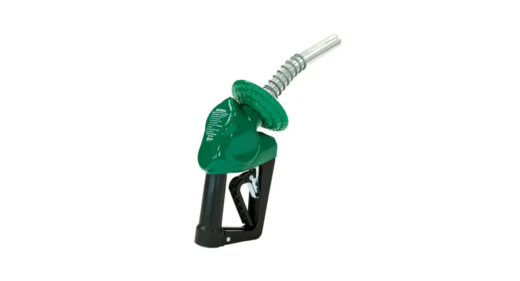
![]() 209808 Conventional Nozzles
209808 Conventional Nozzles
Instruction Manual
X & 1A Nozzles
| ^74703N | ^159404N | ^159463N | 209808 | ^265704N | ^696104N | ^1503004N | ^2098238N |
| ^74704N | 159407 | ^159464N | ^209843N | 265707 | 696107 | 1594120 | ^6961208N |
| 74707 | 159408 | 159466 | ^209859N | ^498403N | 696108 | 1594124 | ^6961209N |
| ^74759N | ^159423N | 159467 | ^209861N | ^498404N | ^696159N | ^1594184N | |
| ^74761N | ^159424N | ^159494N | 209866 | 498407 | ^696161N | 1594235 | |
| ^74772N | ^159443N | ^209803N | 209867 | 498408 | ^696172N | ^1594238N | |
| ^74773N | ^159454N | ^209804N | ^209872N | 498466 | ^696173N | ^2098208N | |
| ^159403N | ^159459N | 209807 | ^265703N | ^696103N | ^1400204N | ^2098209N |
See Listings For Details
Important safety instructions – save these instructions in a readily accessible location![]() WARNING: Cancer and Reproductive Harm – www.p65warnings.ca.gov
WARNING: Cancer and Reproductive Harm – www.p65warnings.ca.gov![]() WARNING Designed for use at motor fuel dispensing facilities only.
WARNING Designed for use at motor fuel dispensing facilities only.
INSTALLATION INSTRUCTIONS
- Turn off the dispenser and relieve line pressure.
- Use pipe thread sealant (not Teflon ape) approved for gasoline on the male threads of the hose section.
- Tighten approximately 1 or 2 turns past hand tight – do not over-tighten.
- Pressurize the system and visually check for leaks.
- Test nozzle for proper automatic shut off between 5 – 10 gpm / 18.9 – 37.9 Lpm.
DO NOT OVER-TIGHTEN. USE WRENCH ON HOSE NUT ONLY.
IF DRIVE-OFF OCCURS
- Turn off the dispenser and relieve line pressure.
- Visually check for fractured spout shear groove.
- Check for leaks.
- Check spout tip – should be in a round and the sensing port should be clear of debris.
- Perform flow test of nozzle automatic shut off between 5 – 10 gpm / 18.9 – 37.9 Lpm.
- Check for electrical conductivity.
TESTING / MAINTENANCE / INSPECTION
![]() Daily
Daily
- Check for leaks/stains.
- Check for loose spouts.
- Check for damage.
- Check for the bent lever.
- Check for broken clip/trigger spring.
![]() Monthly
Monthly
- Check nozzle automatic shut off between 5 – 10 gpm / 18.9 – 37.9 Lpm.
- Check the “remove after” date.
![]() Annually
Annually
- Check for electrical conductivity.
- Lubricate the main valve stem.
- All driveways, maintenance, and inspection activities must be logged using the serial number of the individual product.
- Apply city, state, or federal testing regulations as appropriate.
ANY TEST / INSPECTION FAILURE REQUIRES IMMEDIATE EQUIPMENT REPLACEMENT OR REMOVAL FROM SERVICE.
MADE IN THE USA
![]() ALWAYS ADHERE TO INSTALLATION / USAGE INSTRUCTIONS AND WARNINGS.
ALWAYS ADHERE TO INSTALLATION / USAGE INSTRUCTIONS AND WARNINGS.![]()
Improper use may result in injury, damage, or hazardous spill.
![]() GENERAL WARNINGS / INSTRUCTIONS PERTAINING TO A RISK OF FIRE, ELECTRIC SHOCK, OR INJURY TO A PERSON:
GENERAL WARNINGS / INSTRUCTIONS PERTAINING TO A RISK OF FIRE, ELECTRIC SHOCK, OR INJURY TO A PERSON:
| • Use of equipment is at individuals’ own risk. | |
| • Always abide by and adhere to city, state, and federal regulations regarding the use and installation of dispensing equipment. | |
| • Always follow the product manufacturer’s installation and maintenance instructions. | |
 | • Always turn off all power to the dispenser during maintenance and inspection activities. |
| • Always close the shear valves during maintenance and inspection activities. | |
| • Always relieve pressure from the system prior to performing maintenance activities. | |
 | • Always check continuity after installation using a megohmmeter (Refer to PEI RP 400 for details). |
 | • Always replace or remove from service damaged or leaking dispensing equipment immediately. |
| • Always report leaks/spills/accidents to appropriate authorities. | |
| • Always wear appropriate safety equipment during maintenance activities. | |
 | • Always have appropriate fire extinguishing equipment within 5 ft / 1.5 m of dispensers. |
| • Always use pipe sealant approved for gasoline service. |
| • Always place containers on the ground before filling them. | |
| • Always discharge static electricity before using or servicing equipment by touching a metal part of the dispenser before and after fueling the vehicle. | |
| • Never smoke within 20 ft / 6.1 m of dispensers. | |
| • Never keep in service past recommended life. | |
| • Never leave the nozzle unattended while dispensing fuel. | |
| • Never use sparking or flaming devices within 20 ft / 6.1 m of dispensers. | |
 | • Never use power tools near dispensers or to aid in the installation process. |
| • Never use a cell phone within 20 ft / 6.1 m of dispensers. | |
 | • Never reenter the car when fueling the vehicle. |
| • Never allow gasoline to touch eyes or skin. | |
| • Never use at flow rates in excess of regulatory guidelines. | |
 | • Never use at flow rates less than 5 gpm / 18.9 Lpm. |
| • Never dispense flammable material into unapproved containers. | |
| • Never dispense fuel without a valid driver’s license. |
CAUTION: DO NOT TOP OFF!
Topping off can lead to spills and splashes.
Important safety instructions – save these instructions in a readily accessible location
WARRANTY
VAPOR PRODUCTS – Husky Corporation will, at its option, repair, replace, or credit the purchase price of any Husky ® manufactured product which proves upon examination by Husky, to be defective in material and/or workmanship for a period of one (1) year of installation or fifteen (15) months from the manufacture date of shipment by Husky, whichever occurs first. The warranty period on repaired or replacement vapor recovery products is only for the remainder of the warranty period of the defective product.
CONVENTIONAL PRODUCTS – Husky Corporation will, at its option, repair, replace, or credit the purchase price of any Husky manufactured product which proves upon examination by Husky, to be defective in material and/or workmanship for a period of one (1) year from the manufacture date of shipment by Husky.
Buyer must return the products to Husky, transportation charges prepaid. This Warranty excludes the replaceable bellows, bellows spring assembly, spout assembly, and scuff guard, unless (i) damage is obvious when the product is removed from the shipping carton and (ii) the defective product is returned to Husky prior to use. This warranty does not apply to equipment or parts which have been installed improperly, damaged by misuse, improper operation or maintenance, or which are altered or repaired in any way. The warranty provisions contained herein apply only to original purchasers who use the equipment for commercial or industrial purposes. There are no other warranties of merchantability, fitness for a particular purpose, or otherwise, and any other such
warranties are hereby specifically disclaimed.
Husky assumes no liability for labor charges or other costs incurred by Buyer incidental to the service, adjustment, repair, return, removal or replacement of products. Husky assumes no liability for any incidental, consequential, or other damages under any warranty, express or implied, and all such liability is hereby expressly excluded.
Husky reserves the right to change or improve the design of any Husky fuel dispensing equipment without assuming any obligations to modify any fuel dispensing equipment previously manufactured.
OPERATION INSTRUCTIONS
- Activate the dispenser.
- Insert the spout into the fill pipe opening.
- Lower the hose end of the nozzle so the spout spring catches the inside of the fill pipe.
- Raise the lever and begin fueling.
- The nozzle will shut off automatically when the tank is full.
- Wait 15 seconds to allow any fuel remaining in the spout to drain.
- Remove the nozzle from the fill pipe by raising the hose end of the nozzle.
- Return the nozzle to the nozzle boot.
NOTE: The nozzle is equipped with a unique Flo-Stop ® device that shuts off the nozzle if it falls from the fill pipe or raises above the horizontal.
FLO-EQUALIZER ® INSTALLATION INSTRUCTIONS
Model 004490 Standard Flo-Equalizer ®
- Turn off the dispenser and relieve line pressure.
- Install pipe nipple (if necessary) to achieve proper flow direction.
- Use thread sealant on male threads — DO NOT use Teflon tape.
- Tighten approximately ½ turn past hand tight – do not over-tighten.
- Confirm the nozzle is properly installed, pressurize the system, and check for leaks.
DISCLAIMER: In the event of pressure differential in excess of 25 psi / 1.7 bar across the Flo-Equalizer ® or the presence of debris obstructing the movement of internal components, the Flo- Equalizer ® output may exceed 10 gpm / 37.9 Lpm.
TROUBLESHOOTING GUIDE
| The nozzle keeps shutting off or won’t dispense… | 1. Make sure the dispenser is on and activated. 2. Slow down flow rate – use a lower notch on the clip. 3. Clean spout tip end. 4. Clean or replace the filter. 5. Inspect Safe-T-Break ®. 6. Replace spout assembly. 7. Check dispenser pressure – 19 psi / 1.3 bar to activate the nozzle. |
| The nozzle won’t shut off… | 1. Check flow rate – minimum of 3 gpm / 11.4 Lpm required. 2. Remove the nozzle and drain hose. |
| Nozzle leaks… | 1. Check for the loose spout. 2. Check the hose connection. 3. Check for cracks in the nozzle and hose threads. |
| Low flow rate… | 1. Remove Flo-Equalizer ® (if equipped). 2. Verify dispenser is not in slow flow rate mode. 3. Check for system leaks. |
| Flow rate above 10 gpm / 37.9 Lpm… | 1. Verify Flo-Equalizer ® being used – either inside or outside dispenser. 2. Check Flo-Equalizer ® for debris. |
GENERAL TECHNICAL DATA
| Fuel Type | Test and warranty for gasoline and diesel fuel |
| Flow Rate | X Unleaded w/o Flo-Equalizer ® = 14 gpm / 52.9 Lpm Light Duty Diesel w/o Flo-Equalizer ® = 16 gpm / 60.5 Lpm 1A Unleaded w/o Flo-Equalizer ® = 20 gpm / 90.9 Lpm Light Duty Diesel w/o Flo-Equalizer ® = 25 gpm / 94.6 Lpm |
| Body | Die-cast aluminum |
| Disc | Fluorocarbon |
| Packing | Double O-ring seal protected by fiber-reinforced Teflon ® |
| Lever | One piece of contoured steel |
| Shipping | X Unlead = 3 lbs / 1.3 kg |
| Weight | 1A Unlead = 3.3 lbs / 1.4 kg |
| Threads | X ¾” / 19.1 mm NPT 1A 1″ / 25.4 mm NPT |
| Spout | Unlead = 13/16 in / 20.6 mm O.D. |
| Case Quantity | 15 |
Light Duty Diesel = 3.1 lbs / 1.4 kg
Light Duty Diesel = 3.4 lbs / 1.5 kg
Light Duty Diesel = 15/16 in / 23.8 mm O.D.
| Listings |  | ^ NOT LISTED |
SPOUT REPLACEMENT INSTRUCTIONS
Model 001471 Light Duty Diesel Spout, 001473 Unlead Spout
- Remove the spout lock nut and spout.
- Remove and discard the spout seal.
- Place a new spout seal in the groove.
- Insert the new spout into the body making sure the vent tube is in the port.
- While holding the spout in proper alignment, tighten the spout lock nut firmly, approximately 35 – 60 lbf•ft / 47 – 81 N•m. Do not overtighten.
HOLD OPEN CLIP INSTRUCTIONS
Model 003593 Hold Open Clip Kit
INSTALLATION
- Remove the nozzle from the hose and drain.
- Position the latch springs under the latch clip and hold them in place. The latch clip should straddle the mating holes in the trigger lever.
- Insert latch rivet through latch clip and lever, making sure latch spring is secured in position by the rivet.
- Install push nut on rivet – DO NOT hammer in place.
- Squeeze the lever several times to check the operation.
- Verify clip and lever are parallel.
NOTE: Field installation of the hold open clip is NOT UL approved because improper installation may cause the nozzle to fail.
REMOVAL
- Remove the nozzle from the hose and drain.
- Place the nozzle on a flat surface in a safe location.
- Hold up on the latch clip to prevent the rivet from rotating.
- Drill off the riveted end using a ¼ in / 6.4 mm bit.
- Remove the clip, rivet, and torsion clip spring.
- Do not remove the latch plate.
NOTE: Nozzles can be ordered without clips.
GUARD REPLACEMENT INSTRUCTIONS
| NOZZLE GUARD Model 004145, 000554 1. Turn off the dispenser and relieve line pressure. 2. Remove the nozzle from the hose. 3. Remove the waffle splash guard (if applicable). 4. Remove the old nozzle guard. 5. Install a new nozzle guard over the spout and pull it back to cover the nozzle body. 6. Re-install the nozzle to the hose. 7. Re-install the waffle splash guard (if applicable). 8. Test nozzle for automatic shut off. | NOZZLE REGARD Model 001804, 001806 1. Remove the waffle splash guard (if applicable). 2. Cut the old guard at the nozzle inlet and remove it from the nozzle. 3. Install new nozzle regard over the spout and pull it back to cover the nozzle body. 4. Pull the zip tie through the eyelets and loop under the nozzle inlet. 5. Pull tightly and trim off the excess tie. 6. Re-install the waffle splash guard (if applicable). |
| REGARD PACKAGE Model 001809, 001811 1. Remove the old waffle splash guard. 2. Cut the old nozzle guard at the nozzle inlet and remove it from the nozzle. 3. Install a new nozzle guard over the spout and pull it back to cover the nozzle body. 4. Pull the tie through the eyelets and loop under the nozzle inlet. 5. Pull tightly and trim off the excess tie. 6. Install a new waffle splash guard over the spout lock nut. | WAFFLE SPLASH GUARD Model 001807, 001808 1. Remove the old waffle splash guard. 2. Install new waffle splash guard over spout lock nut. LEVER COVER Model 005494 1. Remove the old lever cover. 2. Snap the new lever cover into place. |
| PROTECTION PACKAGE Model 000099, 001506 1. Turn off the dispenser and relieve line pressure. 2. Remove the nozzle from the hose. 3. Remove the old waffle splash guard (if applicable). 4. Remove the old nozzle guard. 5. Install a new nozzle guard over the spout and pull it back to cover the nozzle body. 6. Install a new waffle splash guard over the spout lock nut. 7. Re-install the nozzle to the hose. 8. Test nozzle for automatic shut off. | POPD ® CLEAR COVER Model 006628 1. Trim advertisement to 3.75 in / 95.25 mm x 3.75 in / 95.25 mm. 2. Notch corners of advertisement approximately .375 in / 9.5 mm x .375 in / 9.5 mm. 3. Turn the clear cover “inside out”. 4. Center advertisement on POPD ® guard, using the notched corners as guides, and fold over the edges. 5. Lay a clear cover over the advertisement, making sure the advertisement stays centered, and turn it “right side out”. 6. Confirm the cover is securely in place. |
| POPD ® GUARD Model 006665, 006655 1. Turn off the dispenser and relieve line pressure. 2. Remove the nozzle from the hose. 3. Remove the waffle splash guard (if applicable). 4. Remove the old nozzle guard. 5. Install a new POPD ® guard over the spout and pull back to cover the nozzle body. 6. Re-install the nozzle to the hose. 7. Re-install the waffle splash guard (if applicable) over the spout lock nut. 8. Test nozzle for automatic shut off. 9. Install desired advertisement and clear cover (model 006628). | POPD ® REGARD Model 007205, 007210 1. Remove the waffle splash guard (if applicable). 2. Cut the old guard at the nozzle inlet and remove it from the nozzle. 3. Install new POPD ® regard over the spout and pull back to cover the nozzle body. 4. Pull the zip tie through the eyelets and loop under the nozzle inlet. 5. Pull tightly and trim off the excess tie. 6. Re-install the waffle splash guard (if applicable). 7. Install desired advertisement and clear cover (model 006628). |
ACCESSORIES
Model 000385 Reducer Bushing ( 1″ / 25.4 mm to ¾” / 19.1 mm)
Model 000397 Unleaded spout gauge
Husky Corporation
• 2325 Husky Way
• Pacific, MO 63069
• Phone: (800) 325-3558
• Fax: (636) 825-7300
• www.husky.com


