Wahoo FITNESS WF131 Powrlink Zero Dual-Sided Power Pedals Installation Guide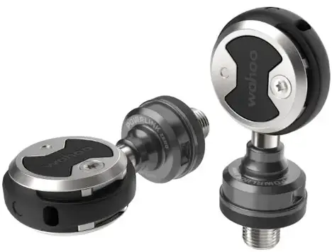
IMPORTANT NOTICE
The following instructions must be observed at all times in order to prevent personal injury and physical damage to equipment and surroundings. The instructions are classified according to the degree of danger or damage which may occur if the product is used incorrectly:
![]() DANGER Failure to follow the instructions will result in death or serious injury.
DANGER Failure to follow the instructions will result in death or serious injury.
![]() WARNING Failure to follow the instructions may result in death or serious injury.
WARNING Failure to follow the instructions may result in death or serious injury.
![]() CAUTION Failure to follow the instructions may cause personal injury and/or physical damage to equipment or surroundings.
CAUTION Failure to follow the instructions may cause personal injury and/or physical damage to equipment or surroundings.
![]() WARNING Follow the instructions provided in the manual when assembling the product.
WARNING Follow the instructions provided in the manual when assembling the product.
![]() WARNING See the Important Product Information included in the product box for additional product warnings and other important information.
WARNING See the Important Product Information included in the product box for additional product warnings and other important information.
For safety, read this manual and all safety information thoroughly before assembly and use.
- Assemble the POWRLINK ZERO only as stated in the information contained in this manual.
- Do not modify the POWRLINK ZERO.
- All instructions can be viewed on our website: www.wahoofitness.com/instructions.
- Images may not reflect final product exactly.
BOX CONTENTS
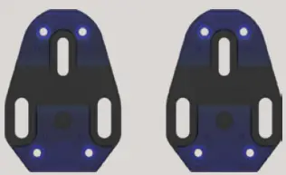
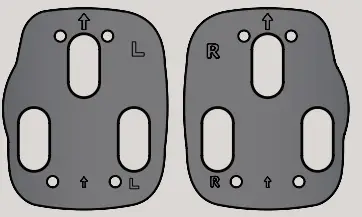
- BASE PLATES
w/ 5-F & 5-R Shims (2x)
- SHIM PACKET
6-F & 6-R Shims (2x), Extra Shims (2x)
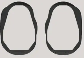
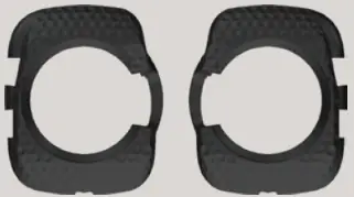
- CLEAT SURROUNDS
1 right / 1 left
- CLEAT COVERS
1 right / 1 left
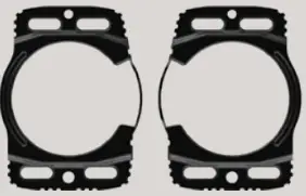
- PROTECTOR PLATES
1 right / 1 left
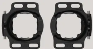
- . SPRING & HOUSING
1 right / 1 left
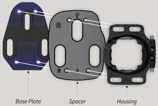
- SPACER
1 right / 1 left
- SCREW PACKET
Base Plate Screws: Short/Black (6x) & Long/Silver (6x), Protector Plate Screws (8x)
- 1MM
WASHERS
- CHARGER

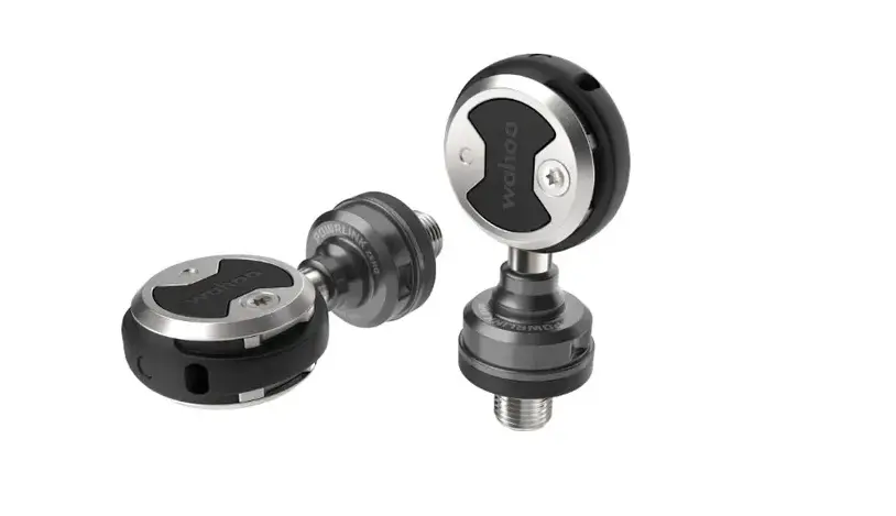
- POWRLINK ZERO PEDALS


TOOLS REQUIRED
![]() #2 Phillips Screwdriver
#2 Phillips Screwdriver
![]() 8mm Allen Wrench
8mm Allen Wrench
CLEAT INSTALLATION
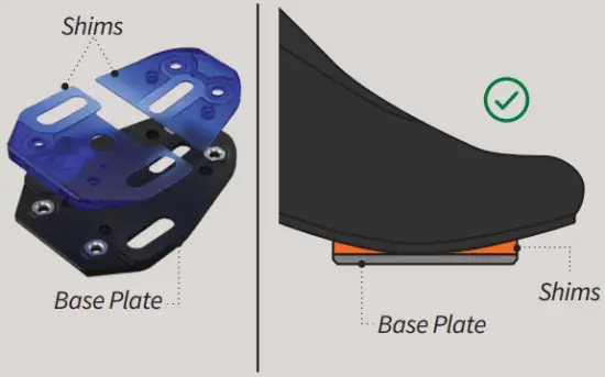
- CHOOSE THE SHIMS FOR THE BASE PLATE THAT BEST FIT THE SOLE OF THE SHOE


5-F and 5-R Shims ship pre-installed to the Base Plates, but can be substituted with the Blue 6-F and 6-R Shims.
Extra Shims may be required between 5-F/6-F Shims and the sole of the shoe. CAUTION
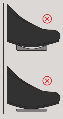
The Base Plate/Shim Combo may not create a “perfect” fit to the bottom of the shoe, but for best results it is important to use the Shims that provide the “best” fit. - SCREW THE BASE PLATE TO THE SHOE USING THE BASE PLATE SCREWS
Base Plate Screws ship in two lengths: (Short/Black & Long/Silver)
Use the shortest screws that allow at least five full turns of engagement with the socket in the sole of the shoe.
Set the desired fore-aft position then tighten the Base Plate Screws.
Recommended tightening torque: 4 Nm.
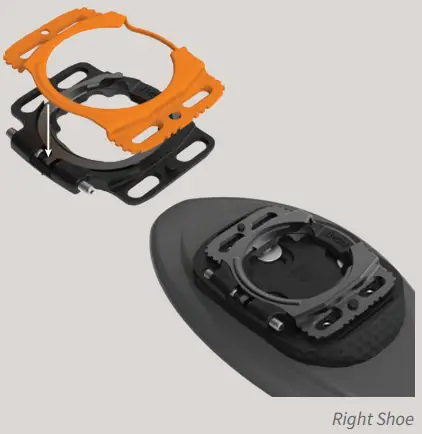
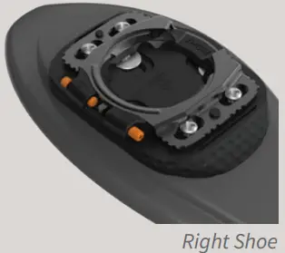
- FIT THE CLEAT SURROUND AROUND THE BASE PLATE
Cleat Surrounds are labeled “L” or “R”.”
- FIT THE PROTECTOR PLATE TO THE SPRING & HOUSING
Spring & Housings are labeled “LEFT” or “RIGHT”. Protector Plates are not labeled.
The Spring & Housing ships pre-assembled to the Protector Plate. If they have separated, gently snap them together using the two small tabs as a guide.
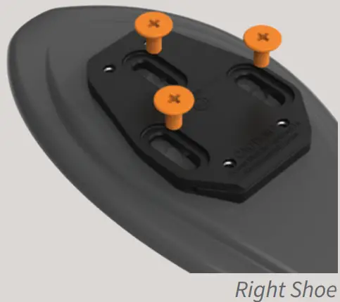
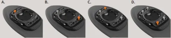
- SCREW THE ASSEMBLY TO THE BASE PLATE USING THE PROTECTOR PLATE SCREWS
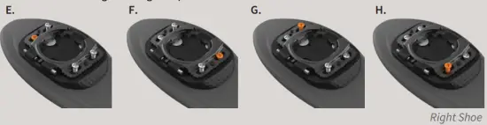
Install the Protector Plate Screws using a “Double X Pattern” (shown below). Loosely engage all four Protector Plate Screws (Steps: A thru D).
Set the desired left-right position then tighten the Protector Plate Screws (Steps: E thru H).
- ADJUST THE LIMIT SCREWS TO SET THE DESIRED FLOAT
Tighten the Limit Screws to reduce the amount of float (“heel movement”) experienced by the foot while pedaling.
Housings are labelled “Heel In” & “Heel Out” to guide which Limit Screws to adjust. Preferred float range is unique to each rider. If you are unsure of your float preference, begin with medium float and adjust as needed.
Note: Do not unscrew the Limit Screws from the Housing when adjusting float, and do not further tighten the Limit Screws once they have made contact with the tip of the Spring.
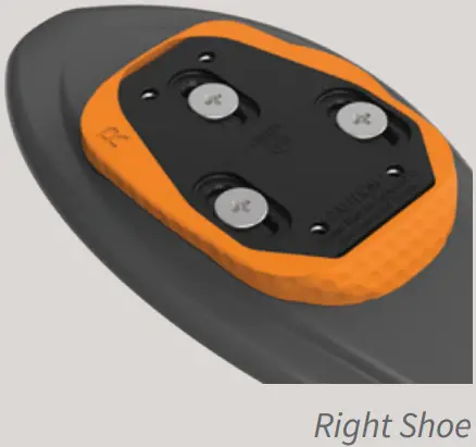
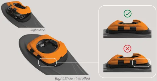
- FIT THE CLEAT COVER OVER THE EDGES OF THE PROTECTOR PLATE
Cleat Covers are labeled “LEFT” or “RIGHT”. Grip the shoe and apply force with the palm of the hand to each of the four corners to ensure that the Cleat Cover has properly covered the edges of the Protector Plate.
The Cleat Cover should fit flush to the Cleat Surround when installed correctly.
Note: Failure to properly complete this step may result in the Cleat Cover falling off.
- APPLY PTFE DRY LUBE TO THE SPRING (OPTIONAL)
Reduce the engagement force required to clip into the pedals by applying a small amount of “PTFE Dry Lube” to the Spring. Wipe away any excess lube.
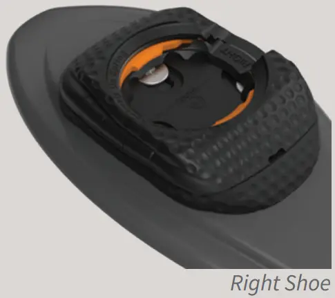
- USE THE SPACER BETWEEN THE BASE PLATE AND HOUSING TO PROVIDE CLEARANCE FOR YOUR SHOES IF THEY COME INTO CONTACT WITH THE POWER POD.
DO NOT use the pedals if your shoe comes in contact with the Power Pod. This will void the warranty.
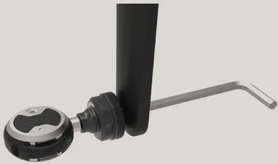
PEDAL INSTALLATION
- CLEAN CRANK ARM THREADS AND APPLY A SMALL AMOUNT OF GREASE
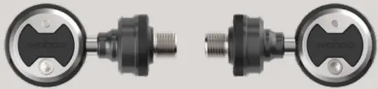
Use a cloth or brush to remove old grease before applying new grease. - IDENTIFY THE LEFT AND RIGHT PEDALS
The “Wahoo” logo reads left-to-right to help identify each pedal (shown-below)
Note: If necessary, use the provided washers to allow for at least 1mm space between the POWRLINK ZERO power pod and your crank arm . CAUTION
Right pedals install clockwise and le pedals install counterclockwise. Improper installation or cross threading can cause damage to your pedals or crank arms. - THREAD THE PEDALS ONTO THE CORRECT CRANK ARM
Use an 8mm Allen Wrench to ensure a snug fit. Recommended tightening torque: 30 Nm.

CHARGING POWRLINK ZERO PEDALS
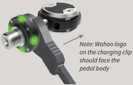
- ENSURE THE CABLE IS SECURELY CONNECTED TO A POWER SOURCE AND TO THE CHARGING CLIPS.
- ATTACH THE CHARGING CLIPS TO THE POWER POD
When firmly attached, the green LEDs will illuminate.
LED INDICATORS
BLUE
SLOW BLINK: Awake and searching
FAST FLASH: Connecting
SOLID: Connected
GREEN
FLASH: Charging
SOLID: Fully charged (will shut off after 5 seconds)
RED
FLASH 3 TIMES: Low battery
NOTE: LEDs turn off after 30 seconds to conserve battery life
APP PAIRING
- DOWNLOAD THE WAHOO APP FOR OPTIMIZED PERFORMANCE AND ESSENTIAL FIRMWARE UPDATES
Ensure Bluetooth is on.


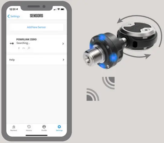
- PAIR SENSOR
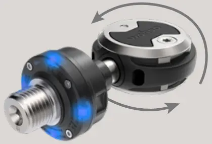
Open app to Sensors page and select “Add New Sensor.” To wake POWRLINK ZERO, rotate pedal around spindle 360°.
- SAVE SENSOR
Your sensor is now set up and ready for action.


CALIBRATION WITH WAHOO APP
- OPEN THE WAHOO FITNESS APP
Ensure the POWRLINK ZERO pedals are nearby and connected.
- NAVIGATE TO THE SENSORS DETAIL PAGE
Tap Settings → Sensors → POWRLINK ZERO
- TAP THE CALIBRATE BUTTON
Once calibration is complete, you’re ready to ride!


ELEMNT PAIRING
- TURN ON YOUR ELEMNT BIKE COMPUTER
Hold left button to power on/off.
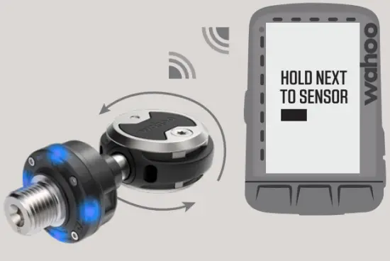
- ACTIVATE PEDAL AND HOLD NEAR YOUR ELEMNT
Rotate pedal around spindle 360° until the blue
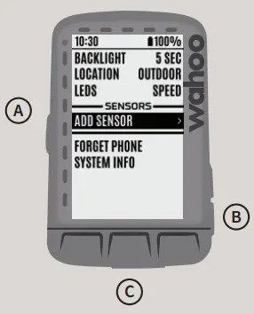
- ADD SENSOR
Press the (a) left Menu button to access the menu. Scroll using the (b) down button on the right side of the ELEMNT to ADD SENSOR and select it by pressing the (c) center button.
- SAVE SENSOR
When POWRLINK ZERO is shown, scroll to select it and press SAVE using the center button.


CALIBRATING YOUR POWRLINK ZERO PEDALS
- WAKE UP YOUR POWER METER
Rotate pedal around the spindle at least 360°.
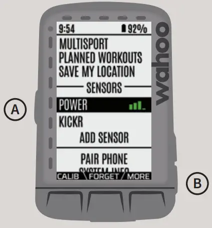
- GO TO SETTINGS MENU
Press the (a) left Menu button to access the Settings menu and scroll to select “paired power meter”
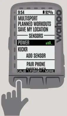
- CALIBRATE
Press the bottom left button to select Calib.
At this point, the ELEMNT Bike Computer has sent the command. It will notify you when calibration is complete.
FCC Statement
This equipment has been tested and found to comply with the limits for a Class B digital device, pursuant to part 15 of the FCC Rules. These limits are designed to provide reasonable protection against harmful interference in a residential installation. This equipment generates, uses and can radiate radio frequency energy and, if not installed and used in accordance with the instructions, may cause harmful interference to radio communications. However, there is no guarantee that interference will not occur in a particular installation. If this equipment does cause harmful interference to radio or television reception, which can be determined by turning the equipment off and on, the user is encouraged to try to correct the interference by one or more of the following measures:
- Reorient or relocate the receiving antenna.
- Increase the separation between the equipment and receiver.
- Connect the equipment into an outlet on a circuit different from that to which the receiver is connected.
- Consult the dealer or an experienced radio/TV technician for help.
Caution: Any changes or modifications to this device not explicitly approved by manufacturer could void your authority to operate this equipment.
This device complies with part 15 of the FCC Rules. Operation is subject to the following two conditions:
- This device may not cause harmful interference, and
- this device must accept any interference received, including interference that may cause undesired operation.
The device has been evaluated to meet general RF exposure requirement.
The device can be used in portable exposure condition without restriction.
IC warning statements:
This device contains license-exempt transmitter(s)/receiver(s) that comply with Innovation, Science and Economic Development Canada’s license exempt RSS(s). Operation is subject to the following two conditions:
- this device may not cause interference, and
- this device must accept any interference, including interference that may cause undesired operation of the device.”
The digital apparatus complies with Canadian CAN ICES-3 (B)/NMB-3(B).
This equipment complies with IC radiation exposure limits set forth for an uncontrolled environment and meets RSS-102 of the IC radio frequency (RF) Exposure rules. This equipment has very low levels of RF energy that are deemed to comply without testing of specific absorption ratio (SAR).


