![]()
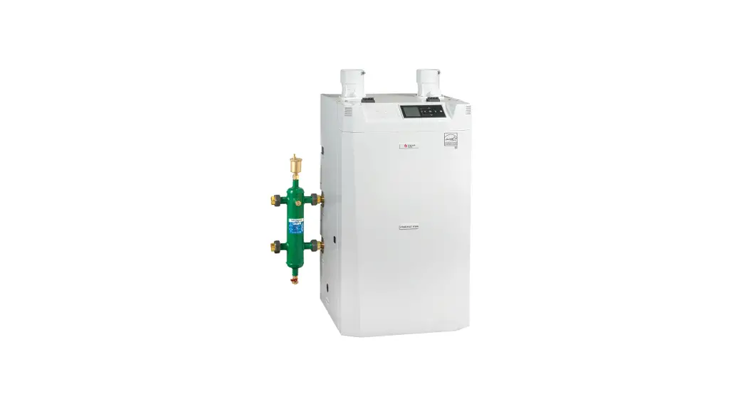
Tube EB073 Instinct Solo Wall
Instruction Manual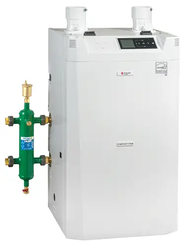
ENGINEERING BULLETIN
EB073 Instinct Solo Wall
Subject:
Gas Valve Adjustment Instructions for Natural Gas and Propane
The following instructions address the adjustment of the appliance gas valve for Natural Gas and Propane. Be sure to review and comply with all SAFETY WARNING labels as noted below.![]()
- Instructions are intended for a qualified installer or service technician only.
- Read all instructions before proceeding.
- Follow instructions in proper order.

![]() If an analyzer is not available, DO NOT make any adjustment to the gas valve. Recommended Tools:
If an analyzer is not available, DO NOT make any adjustment to the gas valve. Recommended Tools:
- Flat Head Screwdriver
- T40 Torques key
- Calibrated Combustion Analyzer
DEFINITIONS
The following terms are used throughout this manual to bring attention to the presence of potential hazards or to important information concerning the product.![]() DANGER
DANGER
Indicates the presence of a hazardous situation which, if ignored, will result in substantial property damage, serious injury, or death.![]() WARNING
WARNING
Indicates a potentially hazardous situation which, if ignored, can result in substantial property damage, serious injury, or death.
CAUTION
Indicates a potentially hazardous situation which, if ignored, can result in minor property damage, or injury.
NOTICE
Indicates special instructions on installation, operation or maintenance, which are important to the equipment but not related to personal injury hazards.
Indicates recommendations made by Triangle Tube for the installers, which will help to ensure optimum operation and longevity of the equipment
![]()
Carbon Monoxide gas can cause serious injury or death. Obey all PPE requirements at all times, and if evacuation is required, vacate immediately Triangle Tube accepts no liability for any damage, injury, or loss of life resulting from incorrect installation, alteration of any factory supplied parts, or the use of parts or fittings not specified by Triangle Tube. If there is a conflict or doubt about the proper installation of the unit or any factory supplied replacement parts please contact Triangle Tube Technical Support.
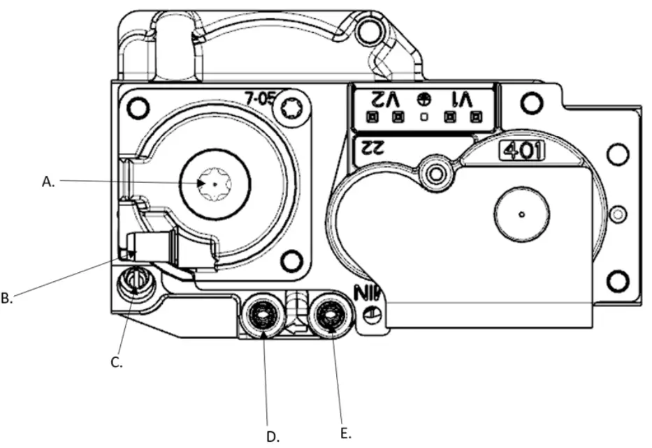
A. Low Fire (Offset) Cap & Adjustment Screw
B. Reference Pressure Connection
C. High Fire Adjuster (Throttle)
D. Low Fire Pressure (Offset Pressure)
E. Gas Inlet Pressure
Diagram 1 – Gas Valve Diagram
| Natural Gar. 110, 155 | Natural Gas 199 | Propane 110.155 | I Propane 199 | ||
| LOW FIRE I HIGH FIRE | CO2 Range | 9.0 to 10.5% | 8.5 to 10.5% | 10.0 to 11.0% | |
| CO2 Target | 10.% | 11.% | |||
| 02 Range | 4.85 to 2.15 % | I 5.75 to 2.15 % | 5.7 to 4.2 % | ||
| 02 Target | 4.% | 5.% | |||
| CO Max | <150 ppm | @ 9.5% CO2 | s200 ppm @ 10.8% CO2 | ||
| CO2 Range | 9.0 to 10.0% | 8.5 to 10.0% | 10.0 to 11.0% | ||
| CO2 Target | 10.% | 9% | 11.% | 110.% | |
| Target values are equivalent to High Fire values, ensure CO2 values measured are less than or equal to High Fire CO2 measurements | Target values are equivalent to High Fire values, ensure CO2 values measured are less than or equal to High Fire CO2 measurements | ||||
| 02 Range | 4.85 to 3.0 % | 5.75 to 3.0 % | 5.7 to 4.2 % | ||
| 02 Target | 4.% | 5.% | 5.% | I 5.1% | |
| Target values are equivalent to High Fire values, ensure 02 values measured are higher than or equal to High Fire 02 measurements | Target values are equivalent to High Fire values, ensure 02 values measured are Where than or equal to High Fire 02 measurements | ||||
| CO Max | 10 ppm | 10 ppm | |||
1. Preliminary Checks
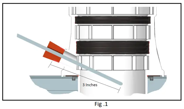
a. Sample probe must be inserted sufficiently, and ensure sampling is correct when CO2/O2 readings are measured (refer to Fig.1 for probe position and insertion).
b. Appliance must be operating in service mode at 100% for high fire and 1% for low fire when CO2/O2 values are measured (Fig.2 / 3). Heating circuit should have all circulation pumps operating, providing sufficient flow through the appliance.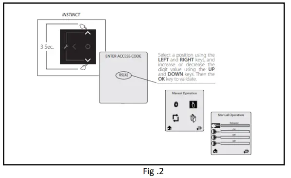
a. Touch simultaneously on the ![]() and
and ![]() soft keys for 3 seconds to access the functions for the installer. Reference
soft keys for 3 seconds to access the functions for the installer. Reference
b. Menthe in alter access code “054* by using the ![]() and
and ![]() . keys to select a digit location and the
. keys to select a digit location and the ![]() and
and ![]() soft keys to change the digit. Touch the
soft keys to change the digit. Touch the ![]() soft key to enter the access code.
soft key to enter the access code.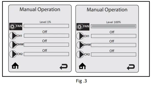
c. Touch the ![]() soft key to highlight the Manual Operation icon
soft key to highlight the Manual Operation icon ![]() then touch the
then touch the ![]() soft key.
soft key.
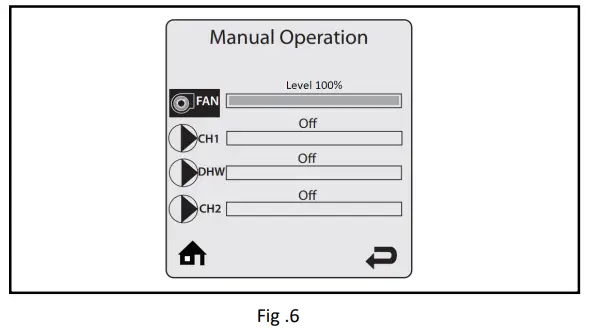
d. Touch the ![]() soft key while the FAN ‘con is highlighted to manually fire the burner and power the CH circulator(s).
soft key while the FAN ‘con is highlighted to manually fire the burner and power the CH circulator(s).
e. Touch the ![]() soft key to adjust ch.% firing rate from 1% to 100%. Hold down the
soft key to adjust ch.% firing rate from 1% to 100%. Hold down the ![]() soft key to rapidly increase the firing rate.
soft key to rapidly increase the firing rate.
Once the combustion level is set at high fire (100%), manually place the boiler into low fire (1%) mode by touching the ![]() soft key to adjust firing rate down.
soft key to adjust firing rate down.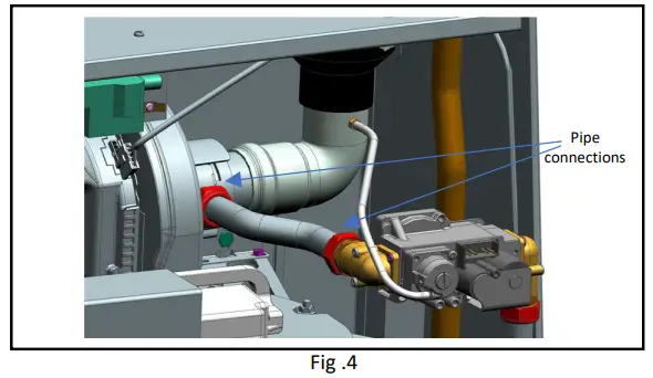 c. Ensure appliance gas valve reference tube is correctly installed and connected with no kinks or splits (Fig.4).
d. Replace fiber washers with the new ones provided (hardware box) (Fig.4).
e. Ensure gas pipe connections are tight and leak free. See Section 10.5 on page 62 from installation guide.
f. Check the incoming gas pressure at the unit (fig.5) is in accordance with table 2 with all gas appliances in operation and standby.
| Minimum | Maximum | |
| Natural Gas | 5 in w.c. | 13 in w.c. |
| Propane (LP) | 8 in w.c. | 12 in w.c. |
Table 2 – Gas Pressure (inches water column)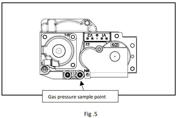
g. If CO2 is below specified tolerance (as per table 1) record High fire CO2/O2 in Table 4 – Section 1A & 1B, then follow section 2 and 3 to adjust High and Low fire Combustion.
Triangle Instinct Solo/Combi Gas Valve Adjustment Instructions
2. High Fire Adjustment (Throttle)
a. Operate boiler to High Fire 100% in service mode (Fig.6).
b. Alter High Fire adjuster (throttle) (fig.7) in ¼ incremental steps until CO2 is within specified tolerance (as per table 3).
c. Wait for stable combustion reading between each adjustment.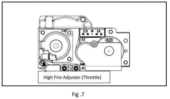
| Direction | INSTINCT Solo/Combi |
| Clockwise | Decrease CO2 / Increase O2 |
| Counter-Clockwise | Increase CO2 / Decrease O2 |
Table 3 – High Fire Adjuster (Throttle)
d. If CO2 levels have reached the limit or high fire adjustment screw (throttle) is fully open*, record High fire CO2/O2 in Table 4 – Section 2A).
*if no stop can be felt remove gas valve and ensure butterfly valve is open all the way (no white seen) (fig.8).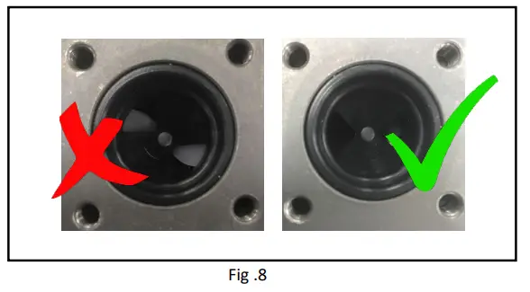 e. Operate appliance to Low fire 1% (fig.9).
f. If CO2 at low fire is below specified tolerance (as per table 1) move to section 3. Low Fire Adjustment.
g. If combustion is within tolerance (as per Table 1) Record Low Fire CO2/O2 in Table 4 – Section 2B and do not adjust low fire Adjuster (offset).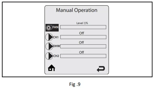
3. Low Fire Adjustment (Offset)
a. Operate appliance at low fire 1% in service mode (Fig.9).
b. Ensure the boiler is at low fire under a stable operating condition whilst monitoring CO2/O2 values.
c. If low fire CO2/O2 values are still below tolerance, record Low Fire CO2/O2 in Table 4 – Section 2B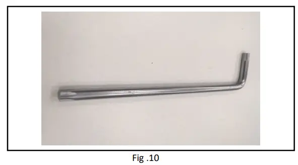
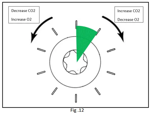
| Direction | INSTINCT Solo/Combi |
| Clockwise | Increase CO2 / Decrease O2 |
| Counter-Clockwise | Decrease CO2 / Increase O2 |
Table 4 – Low Fire Adjuster (Offset)
Using “T40” torques key/bit (fig 10), unscrew, and remove cap of the gas valve low fire adjustment (offset) (Fig.11).
d. Adjust low fire screw (offset) clockwise in small 1/10 the of a turn adjustments until the CO2 measurement is within the tolerance band but no greater than 1% CO2 increase than the combustion reading after throttle adjustment at low fire (Fig.12). Refer to result recorded in Table 4 – Section 2B. 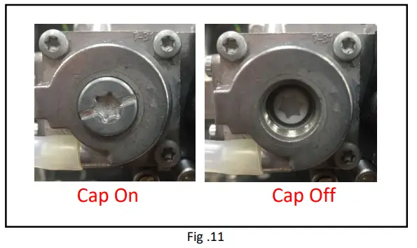
![]()
1% CO2 = 1.8% less O2 on Natural Gas
1% CO2 = 1.5% less O2 on Propane
![]() Valve responds slowly so make smalt 1/10 adjustment to the low fire adjustment screw (offset) and wait for stable combustion reading before repeating.
Valve responds slowly so make smalt 1/10 adjustment to the low fire adjustment screw (offset) and wait for stable combustion reading before repeating.
![]() CO2 measurement should be increased no greater than 1% via low fire adjustment screw (offset) adjustment from previous reading at low fire Refer to result recorded in Table 2 – Combustion Results summary (column 2-Low fire.)
CO2 measurement should be increased no greater than 1% via low fire adjustment screw (offset) adjustment from previous reading at low fire Refer to result recorded in Table 2 – Combustion Results summary (column 2-Low fire.)
e. Record Low Fire CO2/O2 in Table 3 – section 3.B.
f. If minimum CO2/O2 is still below allowed specification tolerance contact triangle tube technical support. Tel: (856) 228 8881
g. Operate appliance to High Fire 100% (Fig.6) Record High Fire CO2/O2 in Table 3 – 3.A).
h. Table 2 – Combustion Results summary should be submitted to Triangle Tube technical support
Instinct model Number:
Serial Number:
Date of Installation:
| Fuel: | Natural gas | Propane |
| 1.Combustion Readings Before Adjustment | 2.Combustion Readings After high fire Adjustment | 3.Combustion Readings After Low Fire Adjustment |
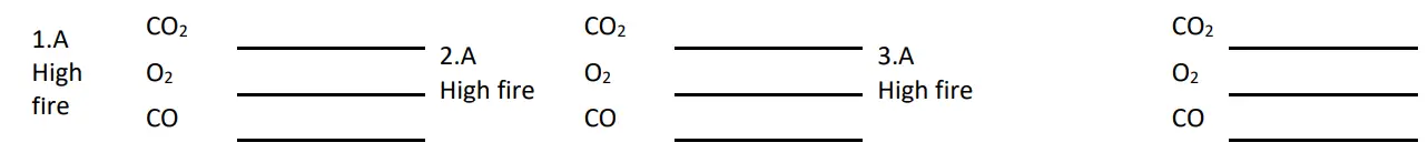
![]() CO2 measurement should be increased no greater than 1% via offset adjustment from previous reading at low fire (column 2. After Throttle Adjustment)
CO2 measurement should be increased no greater than 1% via offset adjustment from previous reading at low fire (column 2. After Throttle Adjustment)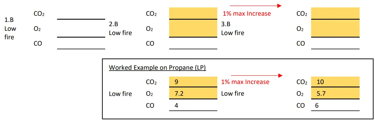 Table 4 – Combustion Results summary
![]()
1% CO2 = 1.8% less O2 on Natural Gas
1% CO2 = 1.5% less O2 on Propane
QR codes to refer to Videos of combustion analyzer / gas valve adjustment / sensing lines + connections 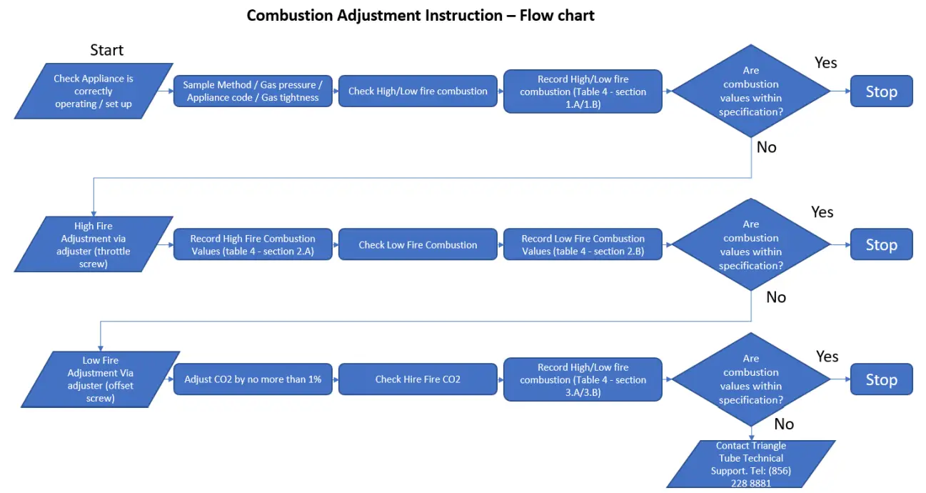
Please contact technical support at [email protected] (856) 228-8881 x575 with any questions.
![]() Triangle Tube – 1240 Forest Parkway,
Triangle Tube – 1240 Forest Parkway,
Suite 100 – West Deptford, NJ 08066
Tel: (856) 228-8881 –
Fax: (856) 228-3584 –
e-mail: [email protected]


