![]()
DRVD
DN50 – 100mm
DN125 – 200mm
Installation manual Manual
DRVD
pressure reducing valve
General
The DRVD pressure reducing valve is intended for use on cold water and drinking water systems. It automatically keeps the downstream pressure at the setpoint value, as long as the inlet pressure is higher.
The DRVD is not affected by upstream pressure variations.
It is particularly recommended for collective and industrial installations of all types.
Fields of application
For the protection of cold water and drinking water systems.
This device reduces and stabilises the pressure at a setpoint value, irrespective of variations in upstream pressure and in the flow drawn into the pipes. The DRVD is ideal for use as a main expansion valve or secondary circuit control valve.
Note: The applications also depend on legislation in the country of use. Please contact your national authorities for further information.
Technical specifications
Type of fluid: drinking water/untreated water
Operation: horizontal position
Connection: flanged in accordance with EN 1092-2
Pressure gauge connection: Female (1/4’’)
Permissible operating pressure:
• PFA 16 bar: adjustment range 1.5 to 6 bar or 2 to 8 bar
• PFA 25 bar: adjustment range 4 to 12 bar
Maximum operating temperature: 40°C
Standards – Approval
Factory testing and hydraulic testing in accordance with EN 12266
Compliance with KTW requirements (Germany) and WRC requirements (UK)
Flange connection in accordance with EN 1092-2, ISO 7005-2
ACS
Operating principle
The DRVD is a direct-acting pressure reducing valve: it is controlled by the downstream pressure, which is exerted under the piston against the force of the spring.
The downstream pressure is exerted directly in the control chamber, under the upper part of the valve through a special orifice.
The downstream pressure is balanced at all times by the action of the spring, which causes the valve to move when the system flow rate or pressure varies.
Installation instructions
2.1 Preliminary inspection
Before installing the device, check that the system and water quality meet the requirements of the regulations in force, in particular NF EN 806-2, NF P40-20, DTU 60.1, and French decree No. 2001-1220.
Also check that it has not been damaged in transit or during handling. Repair if necessary.
Make sure that the pipes on which the pressure reducing valve is to be installed are free from welding residue or other debris. Leave enough space around the pressure reducing valve for the purposes of adjustment and maintenance.
2.2 Mandatory installation conditions
Mandatory horizontal piping, DRVD adjuster screw facing up. The DRVD must be fitted between 2 shut-off valves, one upstream and one downstream, and must be protected by a filter on the upstream side and a drain cock on the downstream side.
Adhere to the diagram below.
The direction in which the valve must be fitted is shown by an arrow on the valve housing.
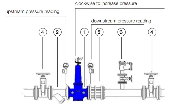
- DRVD pressure reducing valve
- filter
- air release valve
- isolation gate
- dismantling joint
You are advised to ensure ease of access by fitting an isolation device and a filter on the upstream side to prevent damage to the valve.
A dismantling joint must be installed to facilitate all assembly and maintenance operations.
2.3 Conditions of use
Check that the conditions of use match the DRVD delivered.
- Available pressure adjustment ranges: standard 1.5 to 6 baroptional 2 to 8 bar and 4 to 12 bar
- Maximum pressure: 16 bar, consult us for higher pressures
- Cold water, maximum temperature: 40°C
- Maximum flow rate:
| DN | 50 | 65 | 80 | 100 |
| Max flow rate(L/s) | 4.1 | 7 | 10.6 | 16.5 |
| DN | 125 | 150 | 200 | |
| Max flow rate(L/s) | 25.7 | 37.1 | 66 |
Commissioning and adjustment
The DRVD is a direct-acting pressure reducing valve: it is controlled by the downstream pressure, which is exerted under the piston against the force of the spring.
Pressure is adjusted by means of the adjuster screw (100): for DN 50-100, (110): for DN125-200.
Loosen the locknut to release this screw. (220): for DN 50-100, (240): for DN125-200.
- to increase pressure: turn clockwise,
- to reduce pressure: turn anti-clockwise,
The device’s pressure gauge connections are female 8×13 (1/4”).
Adjustment procedure:
- Isolate the DRVD: close the 2 isolation gates (4),
- Open the isolation gate of the air release valve (3); the filter (2) must be clean and the pressure gauges installed,
- Fully decompress the spring of the DRVD by turning the adjuster screw (110) anti-clockwise,
- The pressure needs to be adjusted if the flow rate is low: open a downstream water inlet,
- Open the upstream isolation gate by 3-4 turns,
- Check the upstream pressure, which must be less than the device’s permissible operating pressure,
- Adjust to the setpoint pressure and check on the downstream pressure gauge,
- Close the water inlet,
- Open the upstream and downstream isolation gates (4) completely.
Maintenance instructions
You are advised to have the device checked regularly by a professional.
The device is designed for ease of maintenance. It can be disassembled without removing it. Regularly clean the filter fitted immediately upstream of the DRVD.
Shut off the water before carrying out any maintenance operations. The device must be isolated and depressurised It is imperative to:
- Every 3 months: check the upstream pressure and check the setpoint pressure; adjust the latter if necessary.
- Every 12 months: replace the seal (160).
- Every 3 years: replace all the dynamic seals (available in a single kit – see references below).
Any operations on the device other than maintenance operations must be approved in advance by the AfterSales Service of WATTS INDUSTRIES France.
- All internal parts of the DRVD can be accessed by removing the cover and the lower flange located under the device (Item 200).
- Release the piston by unscrewing the piston screw (or the piston nut depending on the diameter of the DRVD), which can be accessed via the lower flange under the device. Use lock-grip pliers (e.g. FACOM No. 500 or a clamp) to hold the piston
- Unscrew the piston screw with a standard socket wrench (e.g. FACOM No. 72) except for DRVDs with diameters of 125, 150 and 200, for which you will need an elbow-type socket wrench (e.g. FACOM Nervus No. 92).
Maintenance instructions DN 50-100
5.1 Maintenance to be carried out every 12 months
Maintenance and assembly instructions:
- De-presurise the device and then isolate it from the system (remove from system if necessary),
- Fully release the spring (110) (turn the adjuster screw (100) anti-clockwise),
- Remove the valve head fixing screws (200) and then the valve head (20),
- Remove the spring and washers (110-40),
- Open the plug (30) and remove the piston assembly,
- Remove the screw (200), the seal holder (50) and the seal (140),
- Remove the piston (60) from above,
- Remove the lipped seal (160), clean and grease the seals, the seal mating surfaces and seal grooves, then fit the new seal,
- Refit the piston – take care not to damage the seals,
- Refit in reverse order to removal,
- Re-fill with water and adjust as per the instructions provided above.
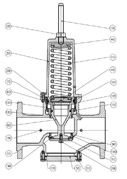
| 10 | valve housing |
| 20 | valve head |
| 30 | plate |
| 40 | spring end washer |
| 50 | seal-holder |
| 60 | guide |
| 70 | piston |
| 80 | spring mounting |
| 90 | seat |
| 100 | adjuster screw |
| 110 | spring |
| 130 | pressure connection |
| 140 | seal |
| 150 | lipped seal |
| 160 | lipped seal |
| 170 | O-ring |
| 180 | O-ring |
| 185 | O-ring |
| 190 | O-ring |
| 195 | ring |
| 200 | fixing screw |
| 210 | fixing screw |
| 220 | lock-nut |
5.2 Maintenance to be carried out every 3 years
Maintenance and assembly instructions:
- De-presurise the device and then isolate it from the system (remove from system if necessary)
- Fully release the spring (110) (turn the adjuster screw (100) anti-clockwise)
- Remove the valve head fixing screws (200) and then the valve head (20)
- Remove the spring and washer (110 / 40)
- Remove the inspection cover (30)
- Remove the screw (200), the seal-holder (50) and the seal (140)
- Remove the piston (60) from above
- Remove the seals (150 – 160 – 195), clean and grease the seal mating surfaces and seal grooves, then fit the new seals
- Refit the piston, taking care not to damage the seals
- Refit the new seal (140)
- Refit in reverse order to removal
- Re-fill with water and adjust as per the adjustment procedures (see 3)
5.3 Modifying the adjustment range by changing the spring kit
Maintenance and assembly instructions:
- De-pressurise the system and then isolate the device from it (remove from system if necessary)
- Fully release the spring (110) (turn the adjuster screw (100) anti-clockwise)
- Remove the valve head fixing screws (200) and then the valve head (20)
- Remove the spring and washer (110 / 40)
- Fit the new spring, with new washers if necessary
- Refit in reverse order to removal
- Re-fill with water and adjust as per the adjustment procedures (see 3)
Maintenance instructions DN 125-200
6.1 Maintenance to be carried out every 12 months
Maintenance and assembly instructions:
- De-pressurise the system and then isolate the device from it (remove from system if necessary),
- Fully release the spring (150) (turn the adjuster screw (110) anti-clockwise),
- Remove the valve head fixing screws (270) and then the valve head (20),
- Remove the spring and washers (150-50),
- Remove the inspection cover (30),
- Remove the nut (140), the sealholder (70), the disc (60) and the seal (160),
- Remove the piston (40) from above,
- Remove the lipped seal (170), clean and grease the seals, the seal mating surfaces and seal grooves, then fit the new seal,
- Refit the piston, taking care not to damage the seals,
- Refit in reverse order to removal,
- Re-fill with water and adjust as per the instructions provided above.
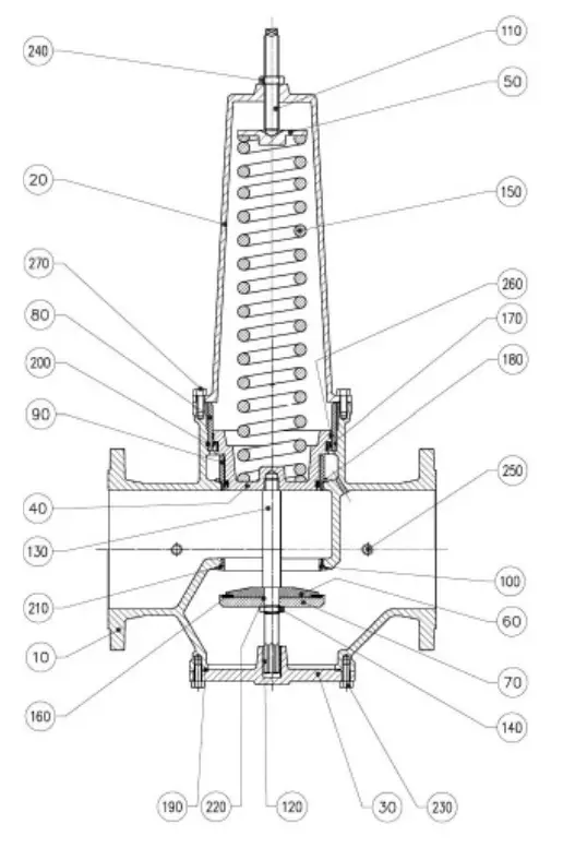
| 10 | valve housing |
| 20 | valve head |
| 30 | plate |
| 40 | piston |
| 50 | spring end washer |
| 60 | closing system |
| 70 | seal-holder |
| 80 | upper ring |
| 90 | lower ring |
| 100 | seat |
| 110 | adjuster screw |
| 120 | ring |
| 130 | shaft |
| 140 | nut |
| 150 | spring |
| 160 | flat seal |
| 170 | lipped seal |
| 180 | lipped seal |
| 190 | O-ring |
| 200 | O-ring |
| 210 | O-ring |
| 220 | O-ring |
| 230 | fixing screw |
| 240 | lock-nut |
| 250 | pressure connection |
| 260 | segment |
| 270 | fixing screw |
6.2 Maintenance to be carried out every 3 years
Maintenance and assembly instructions:
- De-pressurise the system and then isolate the device from it (remove from system if necessary),
- Fully release the spring (150) (turn the adjuster screw (110) anti-clockwise),
- Remove the valve head fixing screws (270) and then the valve head (20),
- Remove the spring and washers (150-50),
- Remove the inspection cover (30),
- Remove the nut (140), the seal-holder (70), the disc (60) and the seal (160),
- Remove the piston (40) from above,
- Remove the seals (170-180-260), clean and grease the seals, the seal mating surfaces and seal grooves, then fit the new seals,
- Refit the piston, taking care not to damage the seals,
- Refit the new seal (160),
- Refit in reverse order to removal,
- Re-fill with water and adjust as per the instructions provided above.
6.3 Modifying the adjustment range by changing the spring kit
Maintenance and assembly instructions:
- De-pressurise the system and then isolate the device from it (remove from system if necessary),
- Fully release the spring (150) (turn the adjuster screw (110) anti-clockwise),
- Remove the valve head fixing screws (270) and then the valve head (20),
- Remove the spring and washers (150-50),
- Fit the new spring, with new washers if necessary,
- Refit in reverse order to removal,
- Re-fill with water and adjust as per the instructions provided above.
Replacement kits
When ordering the kits, quote the information shown on the metal identification plate on the valve housing.
7.1 Seal kits
PN16, PN25 and PN40 seal kits
DN
| mm | “ | Watts code |
| 50 | 2” | 166922 |
| 65 | 2 ½’’ | 202174 |
| 80 | 3” | 162935 |
| 100 | 4 ’’ | 167069 |
| 125 | 5 ’’ | 166929 |
| 150 | 6 ’’ | 162947 |
| 200 | 8 ’’ | 166930 |
| DN 50-100 Item N° | 140,150,160,170,180,000,000,000 |
| DN 125-200 Item N° | 160,170,180,190,200,000,000,000 |
| Composition | 1 kit with 1 piece of each item |
7.2 Spring kits
Spring kits (2 to 8 bar)
DN
| mm | “ | Watts code |
| 50 | 2” | 166921 |
| 65 | 2 ½’’ | 166923 |
| 80 | 3” | 162928 |
| 100 | 4 ’’ | 162931 |
| 125 | 5 ’’ | 202166 |
| 150 | 6 ’’ | 599075 |
| 200 | 8 ’’ | 202167 |
Spring kits (4 to 12 bar)
DN
| mm | “ | Watts code |
| 50 | 2” | 167028 |
| 65 | 2 ½’’ | 166924 |
| 80 | 3” | 166926 |
| 100 | 4 ’’ | 166927 |
| 125 | 5 ’’ | 166928 |
| 150 | 6 ’’ | 167092 |
| 200 | 8 ’’ | 167103 |
![]()
WATTS INDUSTRIES France
1590 avenue d’Orange • CS 10101 Sorgues 84275 VEDENE CEDEX • France
Tel. +33 (0)4 90 33 28 28
• Fax +33 (0)4 90 33 28 39
[email protected]
• www.wattswater.eu
© 2022 Watts
DRVD-IM-FR-W-UK-10-22-Rev.0


