![]() WWW.AXIALADVENTURE.COM
WWW.AXIALADVENTURE.COM
1/10th SCALE READY-TO RUN
SCX10™ III BASE CAMP 1982 CHEVY® K10® INSTRUCTION MANUAL
 https://horizonhobby.cc/3HgR2do?r=qr
Scan the QR code and select the Manuals and Support quick links from the product page for the most up-to-date manual information.
AXI03030 RC Truck RC Jeep and RC Bronco
NOTICE
All instructions, warranties and other collateral documents are subject to change at the sole discretion of Horizon Hobby, LLC. For up-to-date product literature, visit horizonhobby.com or towerhobbies.com and click on the support or resources tab for this product.
MEANING OF SPECIAL LANGUAGE
The following terms are used throughout the product literature to indicate various levels of potential harm when operating this product:
WARNING: Procedures, which if not properly followed, create the probability of property damage, collateral damage, and serious injury OR create a high probability of superficial injury.
CAUTION: Procedures, which if not properly followed, create the probability of physical property damage AND a possibility of serious injury.
NOTICE: Procedures, which if not properly followed, create a possibility of physical property damage AND a little or no possibility of injury.![]() WARNING: Read the ENTIRE instruction manual to become familiar with the features of the product before operating. Failure to operate the product correctly can result in damage to the product, personal property and cause serious injury.
WARNING: Read the ENTIRE instruction manual to become familiar with the features of the product before operating. Failure to operate the product correctly can result in damage to the product, personal property and cause serious injury.
This is a sophisticated hobby product. It must be operated with caution and common sense and requires some basic mechanical ability. Failure to operate this Product in a safe and responsible manner could result in injury or damage to the product or other property. This product is not intended for use by children without direct adult supervision. Do not use with incompatible components or alter this product in any way outside of the instructions provided by Horizon Hobby, LLC. This manual contains instructions for safety, operation and maintenance. It is essential to read and follow all the instructions and warnings in the manual, prior to assembly, setup or use, in order to operate correctly and avoid damage or serious injury.
Age Recommendation: Not for children under 14 years. This is not a toy.
SAFETY PRECAUTIONS AND WARNINGS
As the user of this product, you are solely responsible for operating in a manner that does not endanger yourself and others or result in damage to the product or property of others.
This model is controlled by a radio signal subject to interference from many sources outside your control. This interference can cause momentary loss of control, so it is advisable to always keep a safe distance in all directions around your model as this margin will help avoid collisions or injury.
- Never operate your model with low transmitter batteries.
- Always operate your model in open spaces away from full-size vehicles, traffic and people.
- Never operate the model in the street or in populated areas for any reason.
- Carefully follow the directions and warnings for this and any optional support equipment (chargers, rechargeable battery packs, etc.) you use.
- Keep all chemicals, small parts and anything electrical out of the reach of children.
- Never lick or place any portion of the model in your mouth as it could cause serious injury or even death.
- Exercise caution when using tools and sharp instruments.
![]() WARNING AGAINST COUNTERFEIT PRODUCTS: Always purchase from a Horizon Hobby, LLC authorized dealer to ensure authentic high-quality Spektrum product. Horizon Hobby, LLC disclaims all support and warranty with regards, but not limited to, compatibility and performance of counterfeit products or products claiming compatibility with DSM® or Spektrum technology.
WARNING AGAINST COUNTERFEIT PRODUCTS: Always purchase from a Horizon Hobby, LLC authorized dealer to ensure authentic high-quality Spektrum product. Horizon Hobby, LLC disclaims all support and warranty with regards, but not limited to, compatibility and performance of counterfeit products or products claiming compatibility with DSM® or Spektrum technology.
WATER-RESISTANT VEHICLE WITH WATERPROOF ELECTRONICS
Your new Horizon Hobby vehicle has been designed and built with a combination of waterproof and water-resistant components to allow you to operate the product in many “wet conditions,” including puddles, creeks, wet grass, snow and even rain.
While the entire vehicle is highly water-resistant, it is not completely waterproof and your vehicle should NOT be treated like a submarine.
The various electronic components used in the vehicle, such as the Electronic Speed Control (ESC), servo(s) and receiver are waterproof, however, most of the mechanical components are water-resistant and should not be submerged.
Metal parts, including the bearings, hinge pins, screws and nuts, as well as the contacts in the electrical cables, will be susceptible to corrosion if additional maintenance is not performed after running in wet conditions. To maximize the long-term performance of your vehicle and to keep the warranty intact, the procedures described in the “Wet Conditions Maintenance” section below must be performed regularly if you choose to run in wet conditions. If you are not willing to perform the additional care and maintenance required, then you should not operate the vehicle in those conditions.![]() CAUTION: Failure to exercise caution while using this product and complying with the following precautions could result in product malfunction and/or void the warranty.
CAUTION: Failure to exercise caution while using this product and complying with the following precautions could result in product malfunction and/or void the warranty.
GENERAL PRECAUTIONS
- Read through the wet conditions maintenance procedures and make sure that you have all the tools you will need to properly maintain your vehicle.
- Not all batteries can be used in wet conditions. Consult the battery manufacturer before use. Caution should be taken when using Li-Po batteries in wet conditions.
- Most transmitters are not water-resistant. Consult your transmitter’s manual or the manufacturer before operation.
- Never operate your transmitter or vehicle where lightning may be present.
- Do not operate your vehicle where it could come in contact with salt water (ocean water or water on salt-covered roads), contaminated or polluted water. Salt water is very conductive and highly corrosive, so use caution.
- Even minimal water contact can reduce the life of your motor if it has not been certified as water-resistant or waterproof. If the motor becomes excessively wet, apply very light throttle until the water is mostly removed from the motor. Running a wet motor at high speeds may rapidly damage the motor.
- Driving in wet conditions can reduce the life of the motor. The additional resistance of operating in water causes excess strain. Alter the gear ratio by using a smaller pinion or larger spur gear. This will increase torque (and motor life) when running in mud, deeper puddles, or any wet conditions that will increase the load on the motor for an extended period of time.
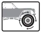
WET CONDITIONS MAINTENANCE - Drain any water that has collected in the tires by spinning them at high speed. With the body removed, place the vehicle upside down and pull full throttle for a few short bursts until the water has been removed.
 CAUTION: Always keep hands, fingers, tools and any loose or hanging objects away from rotating parts when performing the above drying technique.
 - Remove the battery pack(s) and dry the contacts. If you have an air compressor or a can of compressed air, blow out any water that may be inside the recessed connector housing.
- Remove the tires/wheels from the vehicle and gently rinse the mud and dirt off with a garden hose. Avoid rinsing the bearings and transmission.
NOTICE: Never use a pressure washer to clean your vehicle. - Use an air compressor or a can of compressed air to dry the vehicle and help remove any water that may have gotten into small crevices or corners.
- Spray the bearings, drive train, fasteners and other metal parts with a water-displacing light oil. Do not spray the motor.
- Let the vehicle air dry before you store it. Water (and oil) may continue to drip for a few hours.
- Increase the frequency of disassembly, inspection and lubrication of the following:
– Front and rear axle hub assembly bearings.
– All transmission cases, gears and differentials.
– Motor—clean with an aerosol motor cleaner and re-oil the bushings with lightweight motor oil.
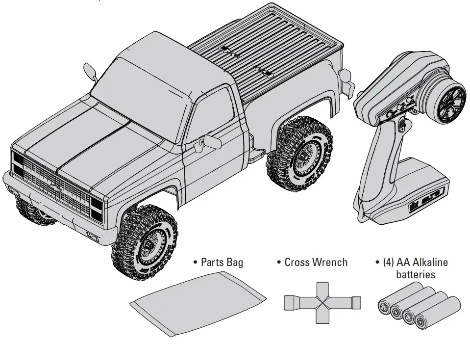
BOX CONTENTS
- Spektrum™ SLT3 3 Channel 2.4GHz Transmitter (SPMRSLT300)
- Axial® SCX10™ III 1982 CHEVY® K10® RTR
– 35T Electric Motor (DYNS1216)
– 40A Smart Brushed ESC (SPMXSE1040)
– Spektrum DSMR® 3 Channel Receiver (SPMSR315)
– Water Proof Metal Gear Surface Servo, 23T (SPMS614)
– (4) AA Alkaline batteries
REQUIRED EQUIPMENT
- 2-3S Standard or “Shorty” LiPo Battery OR
- 5-9 Cell NiMH/NiCd battery (IC3® Connector Required)
- Battery charger compatible with the chosen vehicle battery type


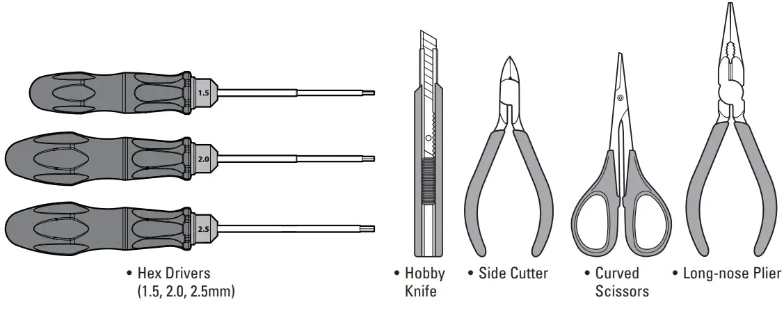
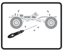
RECOMMENDED TOOLS
GETTING STARTED CHECKLIST
| Read the manual |
| Familiarize yourself with the vehicle and its components |
| Check all screws, especially the driveshaft setscrews, for tightness from the factory |
| Charge the vehicle battery |
| Install 4 AA batteries in the transmitter |
| Install the vehicle battery in the vehicle |
| Power on the transmitter and then connect battery to ESC |
| Check for proper function of the throttle and steering |
| Range check the radio system |
| Drive the vehicle, challenge yourself, and have FUN! |
| Perform any necessary vehicle maintenance |
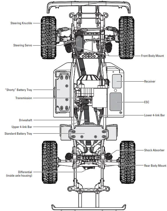
VEHICLE PARTS
CHARGE THE VEHICLE BATTERY
Follow the manufacturer’s directions for your charger to properly charge the vehicle battery.![]() CAUTION: Only use chargers designed to charge the chosen battery type. Using an incorrect charger or incorrect charger settings could cause the battery to catch fire or explode.
CAUTION: Only use chargers designed to charge the chosen battery type. Using an incorrect charger or incorrect charger settings could cause the battery to catch fire or explode.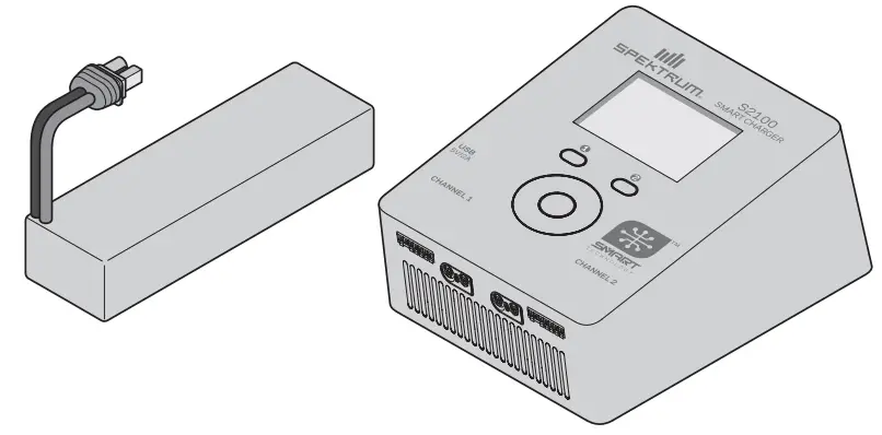
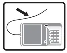
INSTALL THE TRANSMITTER BATTERIES
This transmitter requires 4 AA batteries.
- Remove the battery cover from the transmitter.
- Install the batteries as shown.
- Install the battery cover.
![]() CAUTION: NEVER remove the transmitter batteries while the model is powered on. Loss of model control, damage, or injury may occur.
CAUTION: NEVER remove the transmitter batteries while the model is powered on. Loss of model control, damage, or injury may occur.![]() CAUTION: If using rechargeable batteries, charge only rechargeable batteries. Charging non-rechargeable batteries may cause the batteries to burst, resulting in injury to persons and/or damage to property.
CAUTION: If using rechargeable batteries, charge only rechargeable batteries. Charging non-rechargeable batteries may cause the batteries to burst, resulting in injury to persons and/or damage to property.![]() CAUTION: Risk of explosion if battery is replaced by an incorrect type. Dispose of used batteries according to national regulations.
CAUTION: Risk of explosion if battery is replaced by an incorrect type. Dispose of used batteries according to national regulations.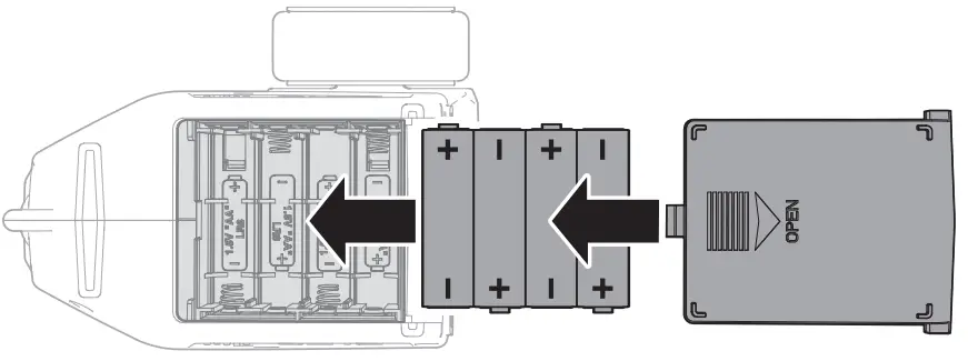
TRANSMITTER FUNCTIONS
SPECIFICATIONS
Power Supply: 4 AA Batteries
Operating Frequency: 2.4GHz
Transmit Power: <100mw
Control Protocol: SLT
Control: Proportional Steering and Throttle/Brake with Trim Knobs,
Third Channel with 3 Position Momentary Switch
Auxiliary Functions: 3 Position Throttle Limit Switch, Steering Rate
Knob to Change Steering Travel on-the-fly, Programmable Servo Travel
for Steering and Throttle/Brake
A. Throttle Trim
Adjusts the throttle neutral point
B. Steering Trim
Adjusts the steering center point. Normally, the steering trim is adjusted until the vehicle tracks straight.
C. LED
- Solid red lights: Indicates the power is ON and adequate battery power
- Flashing red lights: Indicates the battery voltage is critically low.
Replace batteries
D. Steering Wheel
E. Throttle/Brake
F. Steering Rate
On-The-Fly knob for travel adjustment on the steering
G. Channel 3
3 position momentary switch, middle position is neutral
For programming press up for A button, press down for B button
H. Throttle Limit
Limits throttle output to 50/75/100%
Select 50% or 75% for less experienced drivers or when you are driving the vehicle in a small area.
I. Throttle (TH) Servo Reversing
Move the switch to reverse the throttle channel
J. Steering (ST) Servo Reversing
Move the switch to reverse the steering channel
K. Power Button
SPMSR315 DUAL PROTOCOL RECEIVER
SPECIFICATIONS | |
| Type | Dual Protocol 3 Ch Receiver (SLT/DSMR) |
| Dimensions (L × W × H) | 32.5 x 21.5 x 12.4mm |
| Antenna Length | 90mm |
| Channels | 3 |
| Weight | 6g |
| Band | 2.4GHz |
| Voltage Range | 3.5–9.6V |
| Bind Type | Button |

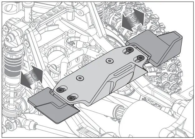
ADJUSTING THE VEHICLE BATTERY TRAY
The battery trays may be adjusted to fit a wide range of battery sizes.
The rear battery tray is shown in the illustration. The side battery tray is adjustable in the same manner.
To adjust the battery tray:
- Loosen the four flathead screws shown in the illustration.
- Slide the ends of the battery tray in or out to fit the desired battery.
- Tighten the four flathead screws. Do not over-tighten the screws.

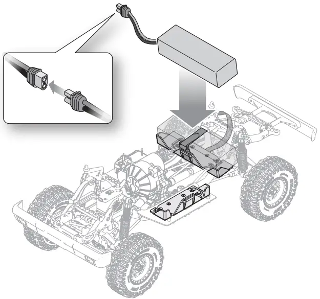
INSTALL THE VEHICLE BATTERY
The following steps show the installation of a standard size battery in the rear battery tray of the vehicle. If you wish to use a “shorty” style battery, it should be installed in the side battery tray location.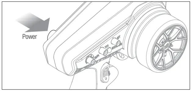
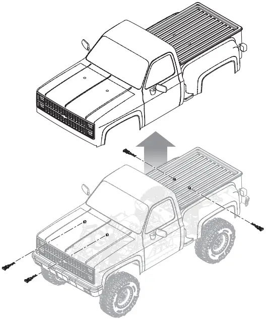
- Power on the transmitter.
- Remove the four body clips from the body.
- Lift the body from the chassis.
- Place the battery in the battery tray. The battery tray length may be adjusted to fit the battery as described in the previous section.


- Secure the battery to the tray with the hook and loop strap.
- Connect the battery to the ESC.
- Re-install the body and four body clips to the chassis.
NOTICE: Always disconnect the battery from the ESC before powering off the transmitter. Loss of vehicle control may result.
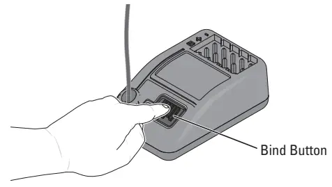
BINDING
Binding is the process of programming the receiver to recognize the GUID (Globally Unique Identifier) code of a single specific transmitter.
Failsafe: Hold the steering wheel and throttle trigger in the desired failsafe positions during binding
- Press and hold the bind button.
- Power ON the receiver. The orange LED will begin to flash.
- Set the trims and control positions at the desired failsafe settings.
- Power ON the SLT3 transmitter.
- When the transmitter’s orange LED remains lit, it is connected to SR315 receiver.
You must rebind when:
- Different failsafe positions are desired (e.g., when throttle or steering reversing has changed).
- Binding the receiver to a different transmitter.

RANGE-CHECKING THE RADIO SYSTEM
The radio system should be checked before operating the vehicle to ensure proper operation and adequate range.
- Turn on the transmitter.
- Connect the battery in the vehicle.
- Have a friend hold the vehicle while keeping hands and loose clothing away from moving parts.
- Walk away until you are at the maximum planned operating distance from the vehicle.
- Turn the steering wheel side to side and operate the throttle, both forward and reverse, checking for any erratic behavior.
- If any erratic behavior is exhibited, DO NOT operate the vehicle. Contact customer service for assistance.


VEHICLE MAINTENANCE
Just like a full size car or truck, your RC vehicle must undergo periodic maintenance in order to ensure peak performance. Preventative maintenance will also help avoid needless breakages which could result in costly repairs. Below are some suggestions to properly maintain your vehicle.
 | Replace any noticeable bent or broken parts |
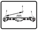 | Check for wear on the ball joints in the steering and suspension links (replace if necessary) |
 | Check driveshaft set screws and apply thread locking compound if necessary |
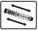 | Inspect shock absorbers for smooth dampened operation |
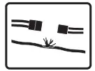 | Check for any loose connections or frayed wiring |
 | Check the wheel nuts for tightness |
 | Ensure the wheel beads are still firmly bonded around the entire circumference of the rim |
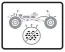 | Keep the chassis free of dirt and debris |
 | Check for loose screws on the chassis, especially the knuckle, C-hub and axle lockout screws |
 | Check the driveline for smooth, bind free operation |
 | If applicable, check the slipper clutch for proper operation |
 | Check the receiver antenna for damage |
 | Check the steering operation for any binding |
 | Inspect the spur and pinion gears for damage |
 | Replace the transmitter batteries when indicated by the transmitter, as described in the Transmitter Functions section |
FIRMA 40A BRUSHED ESC
SETUP
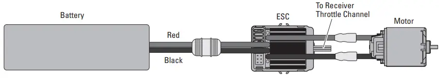
Throttle calibration should not be needed out of the box. However, in order to make the throttle range of different transmitters, the calibration of the ESC is necessary:
- Mount the ESC in an area that is well ventilated and isolated from vibration and shock.
- Connect the ESC motor wires to the motor red-to-red and black-toblack.
- Plug the receiver into the throttle channel of the receiver.
- Before plugging the battery into the ESC, make sure your transmitter is on and the throttle trim is set to zero.
- Connect the battery to the ESC. The vehicle will be powered on when the battery is connected. CAUTION: Keep all body parts and loose clothing away from any moving parts while the battery is connected to the ESC. CAUTION: Always connect the ESC only to a proper power source that has the correct voltage and polarity. Incorrect voltages or reversed polarity will damage the ESC. Damage to the ESC caused by improper voltage or polarity is not covered under warranty.
- Test forward and reverse control using the transmitter.
SPECIFICATIONS | |
| Type | Brushed |
| Constant/Peak | 40A/180A |
| Resistance | 0.002 Ohms |
| Function | Forward/Brake/Reverse, Forward/Brake, Forward/Reverse (Crawler Mode) |
| Vehicle Type | 1/10 on-road and off-road; 1/10 rock crawler |
| Operation | Proportional forward, proportional reverse with braking delay, Crawler Mode |
| Battery Type/Input Voltage | 2–3 cell Li-Po/Li-Fe; 5–9 cell Ni-MH/Ni-Cd |
| Motor Type | 2S Li-Po down to 12T; 3S Li-Po down to 18T |
| BEC Output | 6V/3A |
| Dimensions | 46.5mm x 34mm x 28.5mm (1.8 x 1.3 x 1.1 in) |
| Weight | 70g (2.5 oz) |
| Battery Connector | IC3™ connector |
SOUND INDICATOR | |
| OPERATION | SOUND |
| Ni-MH/Ni-CD Battery | 1 Short Beep |
| 2S Li-Po Battery | 2 Short Beeps |
| 3S Li-Po Battery | 3 Short Beeps |
| ESC Ready | 1 Long Beep |
TO CALIBRATE THE ESC:
- Power the transmitter on and set the throttle control to neutral.
- Connect the battery to the ESC and wait 3 seconds to let the ESC initiate a self-test and automatic throttle calibration.
- The ESC is ready to run when a long beep sound is emitted from the motor.
- Always disconnect the battery when the vehicle is not in use.
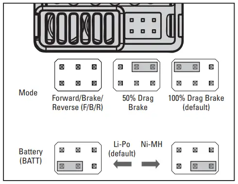
IMPORTANT: The LiPo cut-off is set to “ON” and the drag brake is set to 100% from the factory.
GEAR RATIOS
| SPUR/PINION GEAR RATIO CHART – LCX TRANSMISSION | |||||||
| 12 | 13 | 14 (stock) | 15 | 16 | 17 | 18 | |
| Portal Axles (stock) | 55.1 | 50.9 | 47.2 | 44.1 | 41.3 | 38.9 | 36.7 |
| Standard Axles (optional) | 30.5 | 28.1 | 26.1 | 24.4 | 22.9 | 21.5 | 20.3 |
TROUBLESHOOTING
| PROBLEM | POSSIBLE CAUSE | SOLUTION |
| The system will not connect | Your transmitter and receiver are too close together | Move transmitter 8 to 12 feet away from receiver |
| You are near metal objects | Move to an area with less metal | |
| The receiver is bound to a different model memory | Make sure the correct model memory is active in your transmitter | |
| Your transmitter was placed into bind mode and is no longer bound to your receiver | Rebind your transmitter and receiver, and then re-calibrate | |
| The receiver goes into failsafe a short distance away from the transmitter | Check for damage on the receiver antenna | Make sure your receiver antenna is protected and located as high as practical |
| Replace the receiver or contact Horizon Product Support | ||
| The receiver stops responding during operation | Low receiver battery voltage. If the battery voltage is low, it may drop below 3.5V momentarily, causing the receiver to brown-out, then reconnect | Charge the receiver or vehicle battery. Spektrum receivers require at least 3.5V to operate |
| Loose or damaged wires or connectors between battery and receiver | Check the wires and connection between the battery and receiver. Repair or replace wires and/or connectors | |
| Vehicle does not move | Batteries are not installed properly in the transmitter | Ensure the transmitter batteries are properly installed |
| Weak or no battery in the vehicle | Install a freshly charged vehicle battery | |
| Damaged motor | Replace the motor | |
| Frayed or broken wiring | Replace any damaged wiring | |
| ESC is shut down by heat protection circuit | Allow the ESC to cool down completely | |
| Loss of vehicle control | Improper antenna placement | Ensure the transmitter antenna is not blocked and the receiver antenna is located properly |
| Weak or no batteries in the transmitter or vehicle | Install a freshly charged vehicle battery and new transmitter batteries | |
| Neutral or trim position is incorrect | Adjust the steering trim | |
| Receiver and/or battery not connected properly | Check all receiver and battery connections | |
| Steering and/or throttle function is reversed | Servo travel is reversed at the transmitter | Set the transmitter servo reversing switch to the correct position |
| Motor wires are not connected properly | Check all motor wires for correct polarity and secure connection | |
| ESC ON – No motor function, audible tone or LED | Battery/connection issue | Recharge/replace battery. Secure all connections |
| Damaged ESC | Repair/replace ESC | |
| Damaged motor | Repair/replace | |
| Motor- Stops and LED blinks | Low voltage protection | When the ESC LED blinks, recharge/replace battery |
| Overheat protection | When the LED blinks, let motor/ESC cool, change set up or gearing to avoid overheating | |
| Motor- Accelerates irregularly | Battery issue | Repair damaged wiring/replace battery |
| Incorrect gearing | Adjust/replace gearing | |
| Worn or damaged motor | Repair/replace motor | |
| Motor- Does not turn continuously in response to throttle | ESC/motor damaged | Repair/replace wiring or motor/ESC |
| Motor- Slows but will not stop | Incorrect transmitter/ESC calibration | Adjust throttle travel/other throttle settings on the transmitter/ESC. Repeat the ESC Calibration Procedure |
| Steering servo- Operates; motor does not run | Damaged motor | Test the motor apart from the vehicle system, repair/replace motor as needed |
| Incorrect transmitter/ESC calibration | Adjust throttle travel/other throttle settings on the transmitter/ESC. Repeat the ESC Calibration Procedure | |
| Steering/motor- not functioning | Low battery voltage | Recharge/replace |
| Wrong model memory selected on transmitter | Select correct model settings on your transmitter, refer to transmitter and/or receiver manual | |
| Receiver not bound to transmitter | Bind transmitter to receiver, refer to transmitter and/or receiver manual | |
| Vehicle- Does not operate at full speed | Battery issue | Recharge/replace |
| Incorrect transmitter/ESC calibration | Adjust throttle travel/other throttle settings on the transmitter/ESC. Repeat the ESC Calibration Procedure |
LIMITED WARRANTY
What this Warranty Covers
Horizon Hobby, LLC, (Horizon) warrants to the original purchaser that the product purchased (the “Product”) will be free from defects in materials and workmanship for a period of 2 years from the date of purchase.
What is Not Covered
This warranty is not transferable and does not cover (i) cosmetic damage, (ii) damage due to acts of God, accident, misuse, abuse, negligence, commercial use, or due to improper use, installation, operation or maintenance, (iii) modification of or to any part of the Product, (iv) attempted service by anyone other than a Horizon Hobby authorized service center, (v) Product not purchased from an authorized Horizon dealer, or (vi) Product not compliant with applicable technical regulations or (vii) use that violates any applicable laws, rules, or regulations.
OTHER THAN THE EXPRESS WARRANTY ABOVE, HORIZON MAKES NO OTHER WARRANTY OR REPRESENTATION, AND HEREBY DISCLAIMS ANY AND ALL IMPLIED WARRANTIES, INCLUDING, WITHOUT LIMITATION, THE IMPLIED WARRANTIES OF NON-INFRINGEMENT, MERCHANTABILITY AND FITNESS FOR A PARTICULAR PURPOSE. THE PURCHASER ACKNOWLEDGES THAT THEY ALONE HAVE DETERMINED THAT THE PRODUCT WILL SUITABLY MEET THE REQUIREMENTS OF THE PURCHASER’S INTENDED USE.
Purchaser’s Remedy
Horizon’s sole obligation and purchaser’s sole and exclusive remedy shall be that Horizon will, at its option, either (i) service, or (ii) replace, any Product determined by Horizon to be defective. Horizon reserves the right to inspect any and all Product(s) involved in a warranty claim. Service or replacement decisions are at the sole discretion of Horizon. Proof of purchase is required for all warranty claims.
SERVICE OR REPLACEMENT AS PROVIDED UNDER THIS WARRANTY IS THE PURCHASER’S SOLE AND EXCLUSIVE REMEDY.
Limitation of Liability
HORIZON SHALL NOT BE LIABLE FOR SPECIAL, INDIRECT, INCIDENTAL OR CONSEQUENTIAL DAMAGES, LOSS OF PROFITS OR PRODUCTION OR COMMERCIAL LOSS IN ANY WAY, REGARDLESS OF WHETHER SUCH CLAIM IS BASED IN CONTRACT, WARRANTY, TORT, NEGLIGENCE, STRICT LIABILITY OR ANY OTHER THEORY OF LIABILITY, EVEN IF HORIZON HAS BEEN ADVISED OF THE POSSIBILITY OF SUCH DAMAGES. Further, in no event shall the liability of Horizon exceed the individual price of the Product on which liability is asserted. As Horizon has no control over use, setup, final assembly, modification or misuse, no liability shall be assumed nor accepted for any resulting damage or injury. By the act of use, setup or assembly, the user accepts all resulting liability. If you as the purchaser or user are not prepared to accept the liability associated with the use of the Product, purchaser is advised to return the Product immediately in new and unused condition to the place of purchase.
Law
These terms are governed by Illinois law (without regard to conflict of law principals). This warranty gives you specific legal rights, and you may also have other rights which vary from state to state. Horizon reserves the right to change or modify this warranty at any time without notice.
WARRANTY SERVICES
Questions, Assistance, and Services
Your local hobby store and/or place of purchase cannot provide warranty support or service. Once assembly, setup or use of the Product has been started, you must contact your local distributor or Horizon directly. This will enable Horizon to better answer your questions and service you in the event that you may need any assistance. For questions or assistance, please visit our website at www.horizonhobby.com, submit a Product Support Inquiry, or call the toll free telephone number referenced in the Warranty and Service Contact Information section to speak with a Product Support representative.
Inspection or Services
If this Product needs to be inspected or serviced and is compliant in the country you live and use the Product in, please use the Horizon Online Service Request submission process found on our website or call Horizon to obtain a Return Merchandise Authorization (RMA) number. Pack the Product securely using a shipping carton. Please note that original boxes may be included, but are not designed to withstand the rigors of shipping without additional protection. Ship via a carrier that provides tracking and insurance for lost or damaged parcels, as Horizon is not responsible for merchandise until it arrives and is accepted at our facility. An Online Service Request is available at http://www.horizonhobby.com/content/service-center_renderservice-center. If you do not have internet access, please contact Horizon Product Support to obtain a RMA number along with instructions for submitting your product for service. When calling Horizon, you will be asked to provide your complete name, street address, email address and phone number where you can be reached during business hours. When sending product into Horizon, please include your RMA number, a list of the included items, and a brief summary of the problem. A copy of your original sales receipt must be included for warranty consideration. Be sure your name, address, and RMA number are clearly written on the outside of the shipping carton.
NOTICE: Do not ship Li-Po batteries to Horizon. If you have any issue with a Li-Po battery, please contact the appropriate Horizon Product Support office.
Warranty Requirements
For Warranty consideration, you must include your original sales receipt verifying the proof-of-purchase date. Provided warranty conditions have been met, your Product will be serviced or replaced free of charge. Service or replacement decisions are at the sole discretion of Horizon.
Non-Warranty Service
Should your service not be covered by warranty, service will be completed and payment will be required without notification or estimate of the expense unless the expense exceeds 50% of the retail purchase cost. By submitting the item for service you are greeing
to payment of the service without notification. Service estimates are available upon request. You must include this request with your item submitted for service. Non-warranty service estimates will be billed a minimum of 1/2 hour of labor. In addition you will be billed for return freight. Horizon accepts money orders and cashier’s checks, as well as Visa, MasterCard, American Express, and Discover cards.
By submitting any item to Horizon for service, you are agreeing to Horizon’s Terms and Conditions found on our website http://www.horizonhobby.com/content/service-center_render-service-center.
ATTENTION: Horizon service is limited to Product compliant in the country of use and ownership. If received, a non-compliant Product will not be serviced. Further, the sender will be responsible for arranging return shipment of the un-serviced Product, through a carrier of the sender’s choice and at the sender’s expense.
Horizon will hold non-compliant Product for a period of 60 days from notification, after which it will be discarded.
WARRANTY AND SERVICE CONTACT INFORMATION
| COUNTRY OF PURCHASE | HORIZON HOBBY | CONTACT INFORMATION | ADDRESS |
| United States of America | Horizon Service Center (Repairs and Repair Requests) | servicecenter.horizonhobby.com/RequestForm/ | 2904 Research Rd Champaign, IL 61822 |
| Horizon Product Support (Product Technical Assistance) | [email protected] | ||
| 877-504-0233 | |||
| Sales | [email protected] | ||
| 800-338-4639 | |||
| European Union | Horizon Technischer Service | [email protected] | Hanskampring 9 D 22885 Barsbüttel, Germany |
| Sales: Horizon Hobby GmbH | +49 (0) 4121 2655 100 |
FCC INFORMATION
FCC ID: BRWSPMSLT300
FCC ID: BRWSRIRVINGV1
SUPPLIER’S DECLARATION OF CONFORMITY
Axial SCX10 III Base Camp 1982 Chevy K10 RTR (AXI03030)![]() This device complies with part 15 of the FCC Rules. Operation is subject to the following two conditions: (1) This device may not cause harmful interference, and (2) this device must accept any interference received, including interference that may cause undesired operation.
This device complies with part 15 of the FCC Rules. Operation is subject to the following two conditions: (1) This device may not cause harmful interference, and (2) this device must accept any interference received, including interference that may cause undesired operation.![]() CAUTION: changes or modifications not expressly approved by the party responsible for compliance could void the user’s authority to operate the equipment.
CAUTION: changes or modifications not expressly approved by the party responsible for compliance could void the user’s authority to operate the equipment.
NOTE: This equipment has been tested and found to comply with the limits for a Class B digital device, pursuant to part 15 of the FCC Rules.
These limits are designed to provide reasonable protection against harmful interference in a residential installation. This equipment generates, uses and can radiate radio frequency energy and, if not installed and used in accordance with the instructions, may cause harmful interference to radio communications. However, there is no guarantee that interference will not occur in a particular installation. If this equipment does cause harmful interference to radio or television reception, which can be determined by turning the equipment off and on, the user is encouraged to try to correct the interference by one or more of the following measures:
- Reorient or relocate the receiving antenna.
- Increase the separation between the equipment and receiver.
- Connect the equipment into an outlet on a circuit different from that to which the receiver is connected.
- Consult the dealer or an experienced radio/TV technician for help.
Horizon Hobby, LLC
2904 Research Rd.,
Champaign, IL 61822
Email: [email protected]
Web: HorizonHobby.com
IC INFORMATION
CAN ICES-3 (B)/NMB-3(B)
IC: 6157A-SPMSLT300
IC: 6157A-SRIRVINGV1
This device contains license-exempt transmitter(s)/receivers(s) that comply with Innovation, Science, and Economic Development Canada’s license-exempt RSS(s). Operation is subject to the following 2 conditions:
- This device may not cause interference.
- This device must accept any interference, including interference that may cause undesired operation of the device.
COMPLIANCE INFORMATION FOR THE EUROPEAN UNION
![]() EU COMPLIANCE STATEMENT:
EU COMPLIANCE STATEMENT:
Axial SCX10 III Base Camp 1982 Chevy K10 RTR (AXI03030)
Hereby, Horizon Hobby, LLC declares that the device is in compliance with the following: EU Radio Equipment Directive 2014/53/EU; RoHS 2 Directive 2011/65/EU; RoHS 3 Directive – Amending 2011/65/EU Annex II 2015/863.
The full text of the EU declaration of conformity is available at the following internet address: https://www.horizonhobby.com/content/support-render-compliance.
Wireless Frequency Range and Wireless Output Power Transmitter
2403.0 – 2480.0 MHz
16.3 dBm
Receiver
2404-2476 MHz
-1.33dBm
EU Manufacturer of Record:
Horizon Hobby, LLC
2904 Research Road
Champaign, IL 61822 USA
EU Importer of Record:
Horizon Hobby, GmbH
Hanskampring 9
22885 Barsbüttel Germany
WEEE NOTICE:![]() This appliance is labeled in accordance with European Directive 2012/19/EU concerning waste of electrical and electronic equipment (WEEE). This label indicates that this product should not be disposed of with household waste. It should be deposited at an appropriate facility to enable recovery and recycling.
This appliance is labeled in accordance with European Directive 2012/19/EU concerning waste of electrical and electronic equipment (WEEE). This label indicates that this product should not be disposed of with household waste. It should be deposited at an appropriate facility to enable recovery and recycling.
EXPLODED VIEWS
FRONT AXLE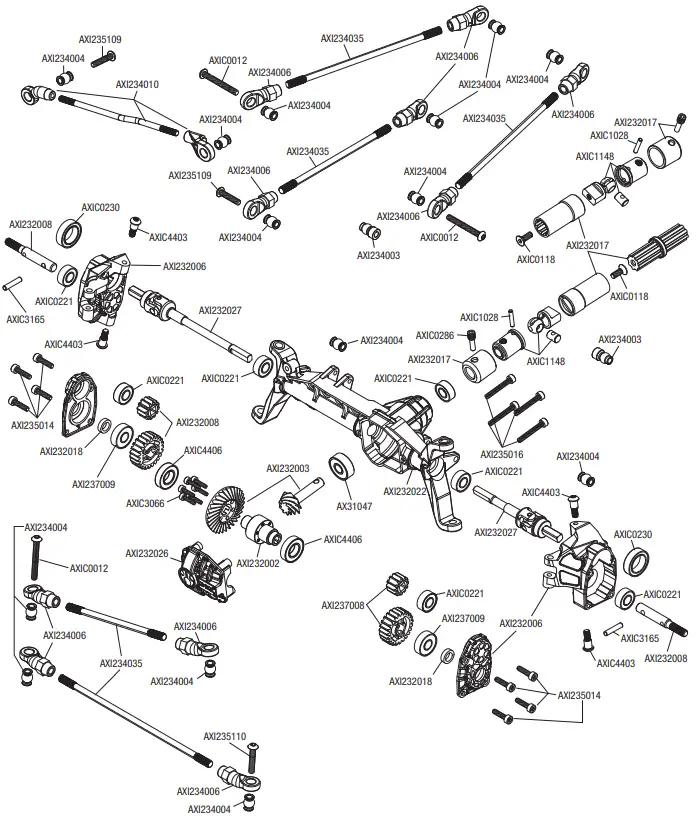 REAR AXLE
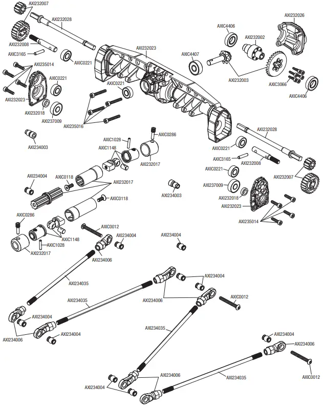 TRANSMISSION
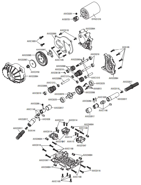 CHASSIS
 BODY ASSEMBLY
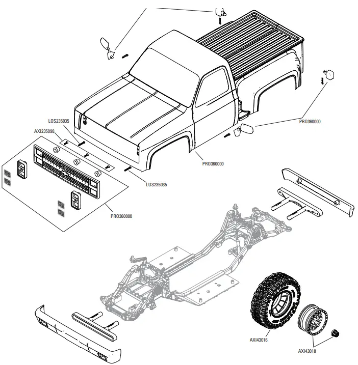 SHOCK ABSORBERS
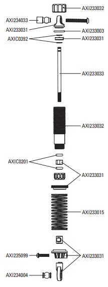
PARTS LISTS
| Part # | Description |
| ARAC9759 | AR722305 Flat Head Screw 3x5mm |
| PRO360000 | 1982 Chevy K10 Clear Body Set w/ Scale Molded Accs |
| AXI230047 | DO FR/RR Bumper Set: SCX10 III BC |
| AXI230048 | Body Post Set: SCX10 III BC |
| AXI231008 | BatteryTray Set/Strap: SCX10 III |
| AXI231009 | Upper Center Lnk Mnts: SCX10 III |
| AXI231010 | Cntr Trans Skid Plate: SCX10 III |
| AXI231011 | Str Mnt Chassis Brace: SCX10 III |
| AXI231012 | Servo Horn, Metal 23T: SCX10 III |
| AXI231015 | Frame Rail Set: SCX10 III |
| AXI231016 | Bmpr/Bdy Mnts Chs FR/RR:SCX10 II |
| AXI231017 | Shktwrs&Pnhrd Mnts Fr/RRSCX10 II |
| AXI231018 | Receiver Box: SCX10 III |
| AXI231021 | Upper Shk Twr Braces: SCX10 III |
| AXI231047 | Skd Plt &Upr Lnk Mnt:SCX10 III BC |
| AXI231048 | Servo Mnt Brace FR: SCX10 III BC |
| AXI231049 | Side Plate&Rr Brace: SCX10 III BC |
| AXI232002 | 6-Bolt Differental Locker |
| AXI232003 | 6-Bolt Heavy Duty Gear Set |
| AXI232017 | Wild Boar Driveshaft Set: UTB |
| AXI232018 | 12mm Hex Pin and Spacer (4): UTB |
| AXI232024 | AR45 Axl Hsng(Fr)SCX10 III |
| AXI232025 | AR45 Axl Hsng (Rr)SCX10 III |
| AXI232033 | InputMtlGears 27,20,34T:SCX10 II |
| AXI232059 | AR45 C-Hub (L-R): SCX10 III |
| AXI232060 | AR45 Knuckle (L-R): SCX10 III |
| AXI232061 | AR45 Unvrsl Axles (2): SCX10 III |
| AXI232062 | AR45 Strght Axles (2): SCX10 III |
| AXI232064 | Gear Cover & Trans Housing: LCXU |
| AXI232065 | Spur Gear 56T 32P: LCXU |
| AXI232066 | Motor Plate: LCXU |
| AXI232067 | Slipper Elimintr Hub&Plate: LCXU |
| AXI232068 | Transmission Metal Gear Set: LCXU |
| AXI232069 | Transmission Shaft Set: LCXU |
| AXI232070 | Trans Center Output Shaft: LCXU |
| AXI233003 | Shock O-Ring Set: UTB |
| AXI233009 | Spring 13x70mm 2.0 lbs/in Ylw(2 |
| AXI233031 | Shock Part Composite:SCX10 III BC |
| AXI233032 | Alum Shck Bdy11x39.5:SCX10 III BC |
| AXI234003 | Pvt Ball,Stainless12.75mm(4):UTB |
| AXI234004 | Susp Pvt Ball, Stainless 7.5mm |
| AXI234006 | HD Rod Ends M4 20pcs: UTB |
| AXI234035 | Susp Link Set 313WB: SCX10 III B |
| AXI235099 | M2.5 x 10mm, Button Head (10) |
| AXI235109 | M3 x 14mm, Button Head Screw(10 |
| AXI235110 | M3 x 16mm, Button Head Screw(10 |
| AXI235178 | M3 x 14mm, Flat Head Screw (10) |
| AXI235230 | M2.5 x 18mm Cap Head Screw (10) |
| AXI236136 | C-Clip, 5mm (10) |
| AXI236172 | Screw Shaft M3x2.0x12mm |
| AXI237009 | 5mmx13mmx4mm Ball Bearing (2) |
| AXI43014 | 1.9 Falken WILDPEAK M/T 4.7” R3 |
| AXI43015 | 1.9 Black Rhino Primm Whl Blk(2 |
| AXIC0012 | AXA120 Hex Socket Btn Hd M3x25 |
| AXIC0013 | AXA013 Cap Hd M2x6mm Blk Oxide |
| AXIC0114 | AXA114 Hex Skt Butn Hd M3x8mm |
| AXIC0115 | AXA115 Hex Skt Butn Head M3x10 |
| AXIC0116 | AXA116 Hex Skt Butn Hd M3x12mm |
| AXIC0118 | AXA144 Hex Flt Hd M3x8mm Blk10 |
| AXIC0146 | AXA146 Hex Skt Flat Hd M3x12mm |
| AXIC0218 | AXA1218 Bearing 5x10x4mm |
| AXIC0221 | AXA1221 Bearing 5x11x4mm |
| AXIC0225 | AXA1225 Bearing 8x16x5mm |
| AXIC0230 | AXA1230 Bearing 10x15x4mm |
| AXIC0286 | AXA0286 Screw Shaft M4x2.5×12 |
| AXIC0291 | AXA291 Set Scr M4x4mm Blk Ox(6 |
| AXIC0392 | AXA1392 E-clip E2 (10) |
| AXIC0569 | AX30569 Pinion 48P 14T Steel |
| AXIC1009 | AXA0109 Hex Skt Oversize M3x10mm |
| AXIC1028 | AX31028 Pin 2.0x11mm (6) |
| AXIC1059 | AXA1059 Body Clip 6mm Black(10) |
| AXIC1120 | AX31120 Hex Skt Flat 3x10mm(10) |
| AXIC1148 | AX31148 Wb8-hd Drvshft Coupler |
| AXIC1180 | AXA118 Hex Socket BtnHd M3x18mm(10) |
| AXIC1181 | AXA119 Hex Socket Btn Hd M3x20(10) |
| AXIC1213 | AXA1213 Bearing 5x8x2.5mm (2) |
| AXIC1391 | AXA1391 E-Clip E4 (10) |
| AXIC3066 | AX31066 Cap Hd M2x8mm Blk (10) |
| AXIC3150 | AX31250 Ser Nyl Nut Blk 4mm(10) |
| AXIC3165 | AX30165 Pin 2.5x12mm (6) |
| AXIC3373 | AX31373 Hex Bttn Head M2.6x8mm (10) |
| AXIC3374 | AX31374 Body Clip Black 3mm(10) |
| AXIC4403 | AX31403 Bttn Hd Scrw M3x4x10mm (6) |
| AXIC4406 | AX31406 Bearing 7x14x3.5mm (2) |
| AXIC4407 | AX31407 Bearing 5x14x5mm (2) |
| DYNS1216 | Dynamite 35-Turn 540 Brushed Motor |
| SPMRSLT300 | SLT3 3CH 2.4Ghz SLT TX Only |
| SPMS614 | S614 Metal Gear Servo 23T WP |
| SPMSR315 | SR315 DSMR 3 CH Receiver |
| SPMXSE1040 | 40A Sensored Brushed Smart ESC |
RECOMMENDED PARTS
| Part # | Description |
| DYNC2030 | Prophet Sport Mini 50W Charger |
| DYNC3015 | P1 Mini AC Balance Char/Dischar |
| DYNC3016 | Passport P2 2 Port AC/DC MultiCharger |
| DYNC3017 | Passport P4 AC/DC 4 Port Multicharger |
| DYNS0900 | Brushed Crawler Combo 35T |
| SPMX50002S100H3 | 5000mAh 2S 7.4V Smart 100C; IC3 |
| SPMX50002S30H3 | 5000mah 2S 7.4V Smart 30C; IC3 |
| SPMX50002S50H3 | 5000mAh 2S 7.4V Smart 50C; IC3 |
| SPMX50003S100H3 | 5000mAh 3S 11.1V Smart 100C; IC3 |
| SPMX50003S30H3 | 5000mah 3S 11.1V Smart 30C; IC3 |
| SPMX50003S50H3 | 5000mAh 3S 11.1V Smart 50C; IC3 |
| SPMXC1000 | Smart S1200 DC Charger, 1x200W |
| SPMXC1010 | Smart S2100 AC Charger, 2X100W |
| SPMXC1050 | Smart S1500 DC Charger, 1x500W |
| SPMXC1070 | Smart S150 AC/DC Charger, 1x50W |
| SPMXC1080 | Smart S1100 AC Charger, 1x100W |
OPTIONAL PARTS
| Part # | Description |
| AXI230025 | Uni Body Post Set: SCX10 III |
| AXI231013 | Servo Horn, Metal 25T: SCX10 III |
| AXI231015 | Frame Rail Set: SCX10 III |
| AXI332001 | 6-Bolt 27/8 Overdrive Gear Set |
| AXIC0724 | AX30724 Pinion Gear 32p 13t |
| AXIC0725 | AX30725 Pinion Gear 32p 14t |
| AXIC0726 | AX30726 Pinion Gr 32p 15t 3mm |
| AXIC0727 | AX30727 Pinion Gear 32p 16t |
| AXIC7028 | AX30728 Pinion Gear 32P 17T |
| SPMXSE1060 | Firma 60ASenseBL Smart Cr ESC |
| SPMXSEMC08 | Firma Sense 1/10 Cr Sys Smart |
| SPMXSM3001 | Firma 2100kv BL Sense Cr Mot |
| SPMXSM3002 | Firma 2800kv BL Sense Cr Mot |
NOTES
 WE.BUILD.ADVENTURE
facebook.com/axialinc | instagram.com/axialracing |
twitter.com/axialrcyoutube.com/axialvideos
WWW.AXIALADVENTURE.COM
©2023 Horizon Hobby, LLC.
Axial, the Axial logo, SCX-10, DSM, DSMR, SLT3, IC3, EC3, Passport, and the Horizon Hobby logo
are trademarks or registered trademarks of Horizon Hobby, LLC.
General Motors Trademarks are used under license to Horizon Hobby, LLC.
The Spektrum trademark is used with permission of Bachmann Industries, Inc.
All other trademarks, service marks and logos are property of their respective owners.
US 9,930,567. US 10,419,970. US 10,849,013. Other patents pending.
Completed 04/23
AXI03030
467219
References
 RC Airplanes and Helicopters, RC Cars and Trucks, RC Boats, RC Radios | Horizon Hobby
-
Horizon Hobby Service Center
-
Instagram
-
Horizon Hobby Service Center
-
RC Cars, RC Trucks, RC Airplanes, Model Trains, and Slot Cars at Tower Hobbies
-
RC Airplanes and Helicopters, RC Cars and Trucks, RC Boats, RC Radios | Horizon Hobby
-
RC Airplanes and Helicopters, RC Cars and Trucks, RC Boats, RC Radios | Horizon Hobby
-
RC Airplanes and Helicopters, RC Cars and Trucks, RC Boats, RC Radios | Horizon Hobby


