Logicbus Convert AC/DC Current to RS485 Modbus
PRELIMINARY WARNINGS
The word WARNING preceded by the symbol indicates conditions or actions that put the user’s safety at risk. The word ATTENTION preceded by the symbol indicates conditions or actions that might damage the instrument or the connected equipment. The warranty shall become null and void in the event of improper use or tampering with the module or devices supplied by the manufacturer as necessary for its correct operation, and if the instructions contained in this manual are not followed.
- WARNING: The full content of this manual must be read before any operation. The module must only be used by qualified electricians. Specific documentation is available via QR-CODE

- The module must be repaired and damaged parts replaced by the Manufacturer. The product is sensitive to electrostatic discharges. Take appropriate measures during any operation
- Electrical and electronic waste disposal (applicable in the European Union and other countries with recycling). The symbol on the product or its packaging shows the product must be surrendered to a collection centre authorized to recycle electrical and electronic waste

CONTACT INFORMATION
- Technical support [email protected]
- Product information [email protected]
This document is the property of SENECA srl. Copies and reproduction are prohibited unless authorised. The content of this document corresponds to the described products and technologies.
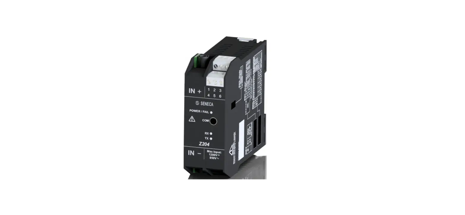
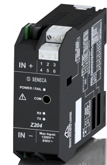
MODULE LAYOUT
SIGNALS VIA LED ON FRONT PANEL
| LED | STATUS | LED meaning |
| PWR/COM Green | ON | The device is powered correctly |
| PWR/COM Green | Flashing | Communication via RS485 port |
| D-OUT Yellow | ON | Digital output activated |
ASSEMBLY
The device can be mounted in any position, in compliance with the expected environmental conditions. Magnetic fields of considerable magnitude can alter the measurement: avoid proximity to permanent magnetic fields, solenoids or ferrous masses which induce strong alterations of the magnetic field; possibly, if the zero error is greater than the declared error, try a different arrangement or change orientation.
USB PORT
The front USB port allows easy connection to configure the device using the configuration software. If it is necessary to restore the initial configuration of the instrument, use the configuration software. Through the USB port it is possible to update the firmware (for further information please refer to the Easy Setup 2 software).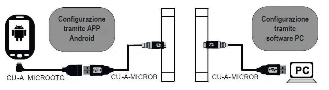
TECHNICAL SPECIFICATIONS
| STANDARDS | EN61000-6-4 Electromagnetic emissions, industrial environment. EN61000-6-2 Electromagnetic immunity, industrial environment. EN61010-1 Safety. | |
| INSULATION | Using an insulated conductor, its sheath determines the insulation voltage. An insulation of 3 kVac is guaranteed on bare conductors. | |
| ENVIRONMENTAL CONDITIONS | Temperature: -25 ÷ +65 °C Humidity: 10% ÷ 90% non condensing. Altitude: Up to 2000 m above sea level Storage temperature: -30 ÷ +85°C Degree of protection: IP20. | |
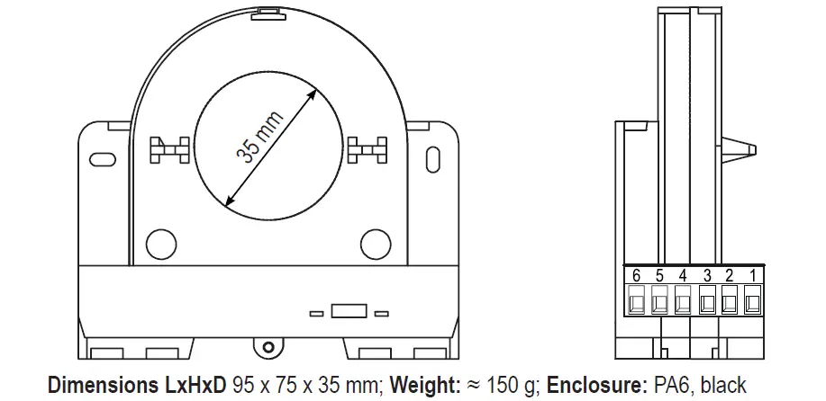
| ASSEMBLY | 35mm DIN rail IEC EN60715, suspended with ties | |
| CONNECTIONS | Removable 6-way screw terminals, 5 mm pitch for cable up to 2.5 mm2 micro USB | |
| POWER SUPPLY | Voltage: on Vcc and GND terminals, 11 ÷ 28 Vdc; Absorption: Typical: < 70 mA @ 24 Vdc | |
| COMMUNICATION PORT | RS485 serial port on terminal block with ModBUS protocol (see user manual) | |
|
INPUT | Type of measurement: AC/DC TRMS or DC Bipolar Live: 1000Vdc; 290Vac Crest factor: 100A = 1.7 ; 300A = 1.9 ; 600A = 1.9 Pass-band: 1.4 kHz Overload: 3 x IN continuous | |
| CAPACITY | AC/DC True RMS | TRMS DC Bipolar (DIP7=ON) |
| T203PM600-MU | 0 – 600A / 0 – 290Vac | -600 – +600A / 0 – +1000Vdc |
| T203PM300-MU | 0 – 300A / 0 – 290Vac | -300 – +300A / 0 – +1000Vdc |
| T203PM100-MU | 0 – 100A / 0 – 290Vac | -100 – +100A / 0 – +1000Vdc |
| ANALOGUE OUTPUT | Type: 0 – 10 Vdc, minimum load RLOAD =2 kΩ. Protection: Reverse polarity protection and over voltage protection Resolution: 13.5 full scale AC EMI error: < 1 % The type of output can be selected via software | |
| DIGITAL OUTPUT | Type: active, 0 – Vcc, maximum load 50mA The type of output can be selected via software | |
|
ACCURACY | below 5% of full scale | 1% of full scale at 50/60 Hz, 23°C |
| above 5% of full scale | 0,5% of full scale at 50/60 Hz, 23°C | |
| Coeffic. Temperature: < 200 ppm/°C Hysteresis on measurement: 0.3% of full scale Response speed: 500 ms (DC); 1 s (AC) al 99,5% | ||
| OVERVOLTAGE CATEGORIES | Bare conductor: CAT. III 600V Insulated conductor:CAT. III 1kV | |
ELECTRICAL CONNECTIONS
WARNING Disconnect the high voltage before carrying out any work on the instrument.
CAUTION
Switch off the module before connecting the inputs and outputs. To meet electromagnetic immunity requirements:
- use properly insulated and dimensioned cables;
- use shielded cables for signals;
- connect the shield to a preferred instrumentation ground;
- Keep shielded cables away from other cables used for power installations (transformers, inverters, motors, etc.).

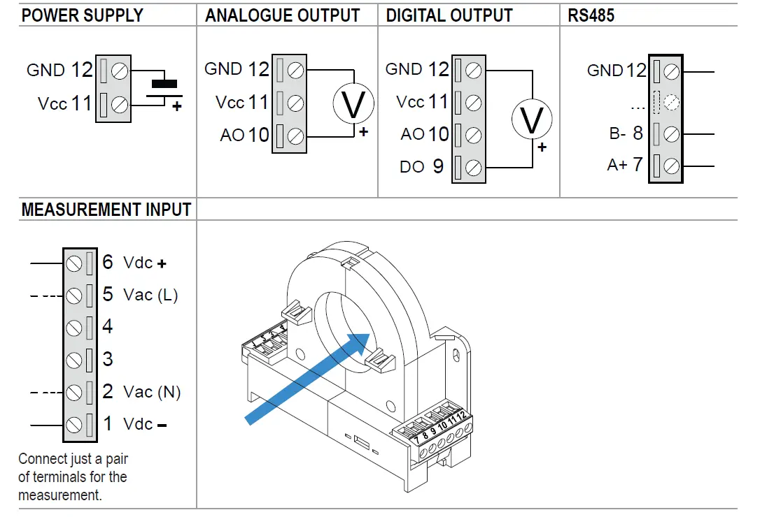
CAUTION
- Make sure that the direction of the current flowing through the cable is that shown in the figure (incoming).
- To increase the sensitivity of the current measurement, insert the cable several times into the central hole of the instrument, creating a series of loops.
- The current measurement sensitivity is proportional to the number of cable passages through the hole.
[email protected]
52 (33)-3823-4349
www.tienda.logicbus.com.mx


