![]() JA72-410 Glove Box with USB-A and USB-C Charger
JA72-410 Glove Box with USB-A and USB-C Charger
User Manual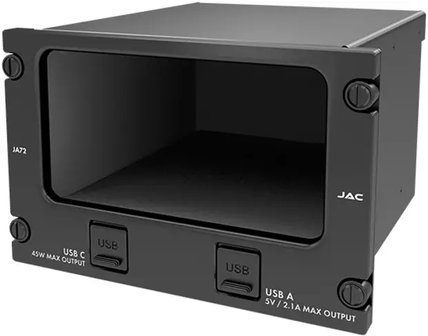
DESCRIPTION
System Overview
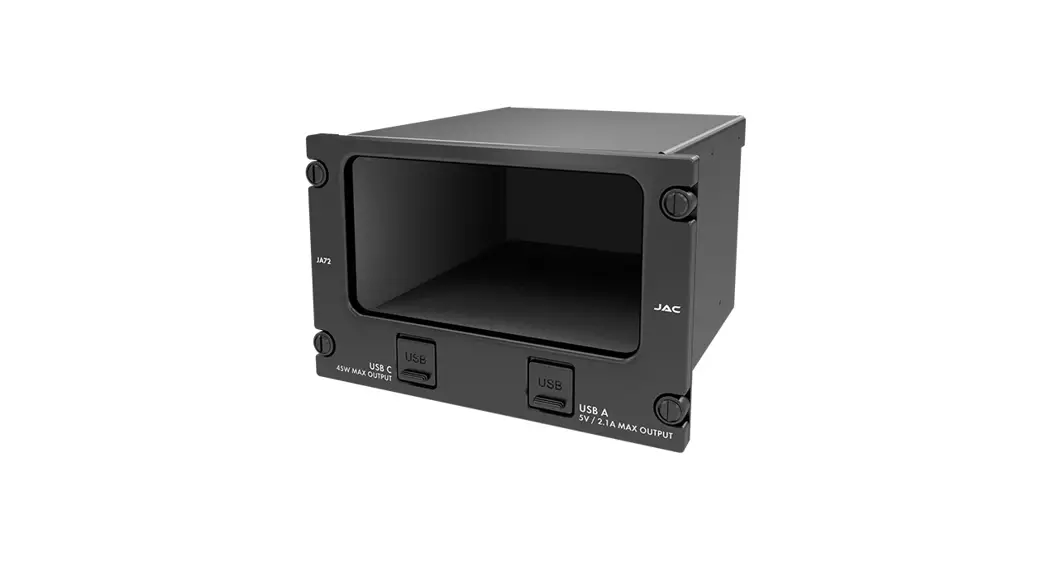
The JA72-410 Glove Box with USB-A and USB-C Charger – 10 Dzus allows the aircraft owner /operator to use an unused portion of the instrument panel for storage. The interior of the glove box has a black anodized finish to minimize scratches.
The JA72-410 uses a 10 Dzus high aperture.
Features Overview
One USB 2.0 Type-A receptacle is provided to supply 5 Vdc power up to 2.1 Amps.
One USB 2.0 Type C receptacle is provided to supply up to 45 Watts.
Inputs and Outputs
Refer to the JA72-410 connector map for the mating connector designators and contact assignments for the input and bi-directional signals.
1.3.1 Inputs
| Name | Qty | Type |
| POWER INPUT | 1 | Power |
| CC1 | 1 | CC1 input |
| CC2 | 1 | CC2 input |
1.3.2 Output
| Name | Qty | Type |
| +5VDC | 1 | USB power output |
| V BUS | 4 | USB power output |
1.3.3 Bi-Directional
| Name | Qty | Type |
| D+ | 1 | Charge sense |
| D- | 1 | Charge sense |
| D+ | 3 | Data |
| D- | 3 | Data |
1.3.4 Grounds/Spares
| Name | Qty | Type |
| POWER GROUND | 1 | Power ground |
| GROUND RETURN | 4 | Ground return |
| CHASSIS GROUND | 1 | Chassis ground |
| SPARE | 3 | Spares (Main connector) |
| SPARE | 10 | Spares (USB-C connector) |
Specifications
1.4.1 Electrical Specifications
| Power Input | |
| Primary nominal voltage | Power Input |
| Maximum voltage | Primary nominal voltage |
| Minimum voltage | Maximum voltage |
| Emergency voltage | Minimum voltage |
| Power Input – Off | Emergency voltage |
| Input current at 28 Vdc | Power Input – Off |
| Input current at 28 Vdc | |
1.4.1.1 USB-A Output Performance
| Output rated current | ≤ 2.1 A |
| Output rated voltage | +5 Vdc ± 10 % |
| Ripple | ≤ 5 mVpp |
| Short circuit | ≥ 1 min |
1.4.1.2 USB-C Output Performance
| Output rated current | 2.25 A for +20 V output 3.00 A for all other voltages |
| Output rated voltage | +5 Vdc ± 5 % +9 Vdc ± 5 % +12 Vdc ± 5 % +15 Vdc ± 5 % +20 Vdc ± 5 % |
| Ripple | ≤ 5 mVpp for +5 V output ≤ 9 mVpp for +9 V output ≤ 12 mVpp for +12 V output ≤ 15 mVpp for +15 V output ≤ 20 mVpp for +20 V output |
| Short circuit | ≥ 1 min for all voltages |
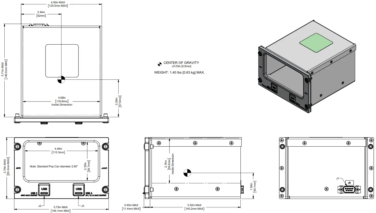
1.4.2 Mechanical Specifications
| Height | 3.75 in [95.3 mm] maximum | |
| Behind panel depth (not including connectors) | 5.52 in [140.2 mm] maximum | |
| Width | 5.75 in [146.1 mm] maximum | |
| Weight | 1.40 lb [0.63 kg] maximum | |
| Enclosure: | 5052-H32 aluminum; brushed texture and black anodized | |
| Faceplate | 6061-T651 Aluminum with flat black urethane paint; white legends | |
| Connectors (3): | J1 Main J2 USB C J3 USB A | One 9-pin D-Sub male, V5 locking One USB Type C Female One USB Type A Female |
| Mounting | 4 Dzus fasteners | |
| Bonding | ≤ 2.5 mΩ | |
| Installation kit part number | INST-JA72 |
1.4.3 Flammability of Materials
The JA72-410 complies with the requirements of RTCA/DO-160G Sec 26.3.3 “Flammability”, through equivalent flammability testing of materials and the Small Parts Exemption.
INSTALLATION
Introduction
This section contains unpacking and inspection procedures, installation information, and post-installation checks.
Continued Airworthiness
Maintenance of the JA72-410 is on condition only. Scheduled inspection and/or periodic maintenance of this unit is not required.
Unpacking and Inspecting Equipment
Unpack the equipment carefully. Check for shipping damage and report any problems to the relevant carrier. Confirm that the Authorized Release Certificate or Certificate of Conformance is included. Complete the online warranty card from the Jupiter Avionics Corporation (JAC) website – www.jupiteravionics.com/warranty.
2.3.1 Warranty
All products manufactured by JAC are warranted to be free of defects in workmanship or performance for 2 years from the date of installation by an approved JAC dealer or agency. This warranty covers the cost of all materials and labor to repair or replace the unit but does not include the cost of transporting the defective unit to and from JAC or its designated warranty repair center, or of removing and replacing the defective unit in the aircraft. This warranty does not cover failures due to abuse, misuse, accident, or unauthorized alteration or repairs.
THIS WARRANTY IS VOID IF THE PRODUCT IS NOT INSTALLED BY AN AUTHORIZED JAC DEALER. If the online warranty card is not completed, the product will be warranted from the date of manufacture.
Contact JAC for a return authorization, and for any questions regarding this warranty and how it applies to your unit(s). JAC is the final arbiter concerning warranty issues.
Installation Procedures
![]() CAUTION: The power input circuitry of the unit may be damaged if the installation does not conform to the wiring instructions in this manual.
CAUTION: The power input circuitry of the unit may be damaged if the installation does not conform to the wiring instructions in this manual.
2.4.1 Installation Limitations
Those installing the JA72, on or in a specific type or class of aircraft, must determine that the aircraft installation conditions meet standards. The JA72 may be installed only by following the applicable airworthiness requirements.
2.4.2 Cabling and Wiring
All wires shall be selected in accordance with the original aircraft manufacturer’s maintenance instructions, or AC43.131B Change 1, Paragraphs 11-76 through 11-78. Follow the Connector Map in Appendix A of this manual.
Note that this unit has a ‘clamshell’ hood that is installed after the wiring is complete.
Maintain wire segregation and route wiring in accordance with the original aircraft manufacturer’s maintenance instructions.
Unless otherwise noted, all wiring shall be a minimum of 20 AWG. Refer to the Interconnect drawing for additional specifications.
2.4.3 Mechanical Installation
The JA72-410 can be mounted in any attitude and location with adequate space for the front panel and sufficient clearance for the connector and wiring harness. It requires no direct cooling.
2.4.6 Post Installation Checks
2.4.6.1 Voltage/Resistance checks
Do not attach this unit until the following conditions are met:
a) Check P1 pin 1 for +28 Vdc relative to ground.
b) Check P1 pin 6 (power ground) for continuity to ground (less than 0.5 Ω).
c) Check P1 pin 7 (chassis ground) for continuity to ground (less than 0.5 Ω).
d) Check all pins for shorts to ground or adjacent pins.
2.4.6.2 Power on Checks
Power up the aircraft’s systems and confirm the normal operation of all functions of the JA72. Refer to Section 3 (Operation) for specific operational details.
When all performance checks are satisfied, complete the necessary regulatory documentation before releasing the aircraft for service. Refer to Appendix B.
Installation Kit
The kit required to install this unit is not included with the unit.
The installation kit (Part # INST-JA72) consists of the following:
| Quantity | Description | JAC Part # |
| 1 | D-Sub 9-pin connector, hood, and 9 crimp pins | CON-3420-0009 |
| 1 | JA72 Assembly Notes, Installation Kit | DOC-INST-JA72 |
2.5.1 Recommended Crimp tools
| Standard D-Sub Crimp Tool Chart | |||
| Tool Type | Hand crimping tool | Positioner | Insertion/extractor tool |
| POSITRONIC | 9507-0-0-0 | 9502-5-0-0 | 4711-2-0-0 |
| DANIELS | AFM 8 | K13-1 | 91067-2 |
| MIL-SPEC | M22520/2-01 | M22520/2-08 | M81969/1-02 |
Installation Drawings
The drawings and documents required for Installation can be found in Appendix A of this manual.
OPERATION
Introduction
This section contains the operating instructions for the JA72-410.
The JA72-410 provides useful storage space with the added benefits of storing and charging two phones or other devices.
The JA72-410 uses a 10 Dzus high panel height.
Front Panel Connectors
The JA72-410 has one front panel USB-A Power output connector and one front panel USB-C Power output connector. 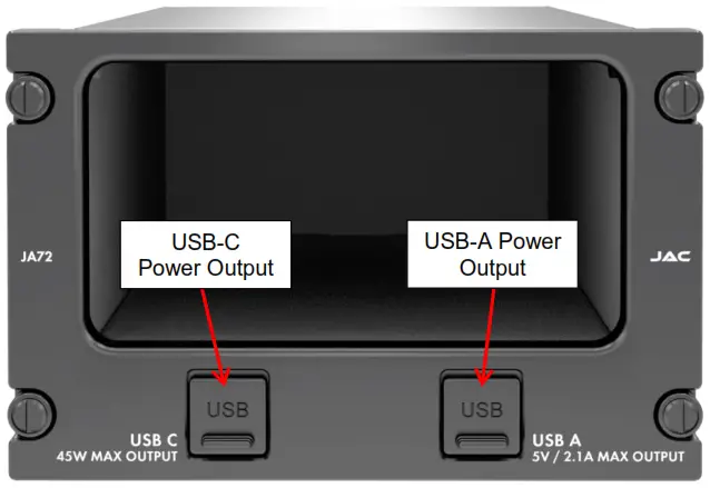
3.2.1 USB-C Power Output
This Power Output is a USB Type C connector.
This connector has a USB PD Type C receptacle with an auto-adjustable supply which can deliver +5 Vdc @ 3 A, +9 Vdc @ 3 A, +12 Vdc @ 3 A, +15 Vdc @ 3 A, or +20 Vdc @ 2.25 A for charging cell phones and similar devices.
3.2.2 USB-A Power Output
This Power Output is a USB Type-A connector.![]() Note: USB-A port is not designed to be used for data transfer. 3.3 Compatibility
Note: USB-A port is not designed to be used for data transfer. 3.3 Compatibility
This connector is provided to supply +5 Vdc up to 2.1 Amps for charging cell phones and similar devices.
Compatibility
![]() CAUTION: Attempting to connect an incompatible plug or device could damage the JA72, the attached device, or both.
CAUTION: Attempting to connect an incompatible plug or device could damage the JA72, the attached device, or both.
If in doubt regarding the compatibility of a specific item, contact Jupiter Avionics (www.jupiteravionics.com).
Appendix A – Installation Drawings
A1 Introduction
The drawings necessary for installation and troubleshooting of the JA72-410 Glove Box with USB-A and USB-C Charger – 10 Dzus are in this Appendix, as listed below.
A2 Installation Drawings
| DOCUMENT | Rev |
| JA72-410 Connector Map | A |
| JA72-410 Interconnect | A |
| JA72-410 Mechanical Installation | A |
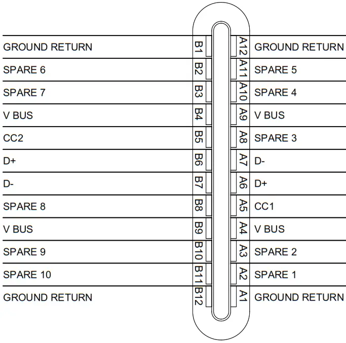
Main ConnectorP1
9 PIN FEMALE DMIN MATING CONNECTOR
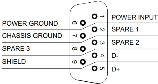 VIEW IS FROM REAR OF MATING CONNECTOR
USB C ConnectorP2
USB TYPE C MALE MATING CONNECTOR
 The view is from the front of the mating connector
USB A ConnectorP3
USB TYPE A MALE MATING CONNECTOR 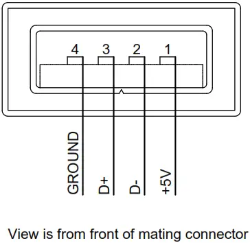
| PREPARED | TAT | |||
| CHECKED | ||||
| TITLE Glove Box with USB-A and USB-C Charger – 10 Dzus Connector Map | ||||
| APPROVED | ||||
| NCAGE CODE L00N3 | PART NO. JA72-410 | SHEET 1/1 | ||
| CONFIDENTIAL & PROPRIETARY TO JUPITER AVIONICS CORP. | DOC NO. JA72-410 Connector Map Rev A.dwg | |||
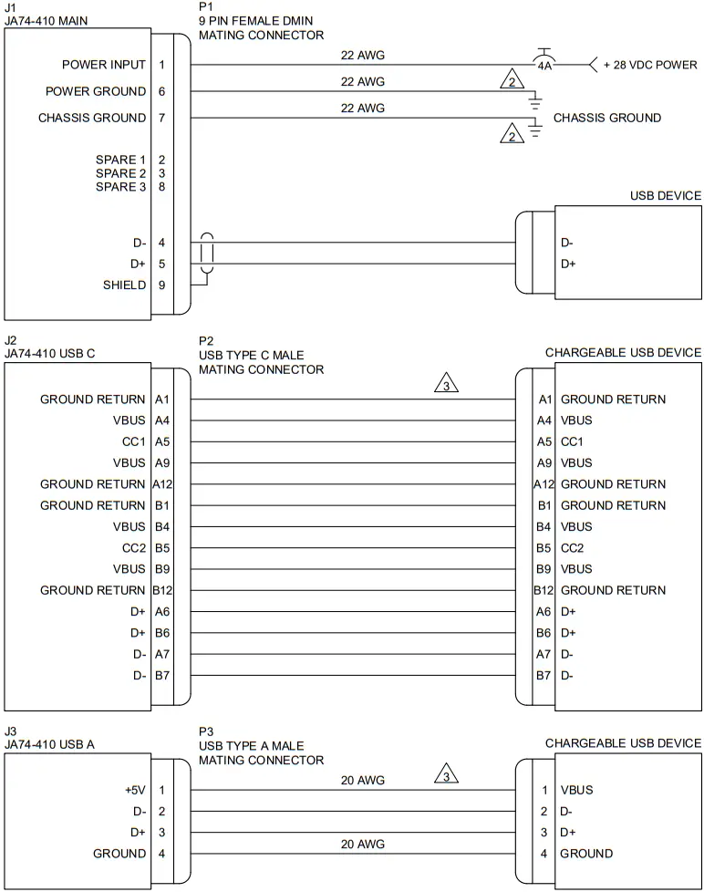
JA72-410 INTERCONNECT WIRING NOTES
NOTES
- ALL WIRE SIZES SHOULD BE 22 AWG MIN UNLESS OTHERWISE SPECIFIED. UNSHIELDED WIRE SHOULD BE SELECTED PER FAA AC43.13-1B CHANGE 1 PARA 11-76 TO 11-78. WIRE TYPES SHOULD BE IN ACCORDANCE WITH MIL-W-22759 AS DESCRIBED IN FAA AC43.13-1B CHANGE 1 PARA 11-85 AND 11-86 AND LISTED IN TABLE 11-11 OR 11-12. ALL SHIELDED CABLES SHOULD BE IN ACCORDANCE WITH MIL-DTL-27500 (REVISION H OR LATER).
- CONNECTIONS TO AIRFRAME GROUND SHOULD BE MADE WITH 22 AWG WIRE. LENGTH NOT TO EXCEED 3 FT (0.91 M).
- CABLE LENGTHS ARE NOT TO EXCEED 6 FT (1.82 M).
| PREPARED | TAT | |||
| CHECKED | ||||
| TITLE Glove Box with USB-A and USB-C Charger – 10 Dzus | ||||
| APPROVED | ||||
| NCAGE CODE L00N3 | PART NO. JA72-410 | SHEET 1/2 | ||
| CONFIDENTIAL & PROPRIETARY TO JUPITER AVIONICS CORP. | DOC NO. JA72-410 Interconnect Rev A.dwg | |||
| PREPARED | TAT | |||
| CHECKED | ||||
| TITLE Glove Box with USB-A and USB-C Charger – 10 Dzus | ||||
| APPROVED | ||||
| NCAGE CODE L00N3 | PART NO. JA72-410 | SHEET 2/2 | ||
| CONFIDENTIAL & PROPRIETARY TO JUPITER AVIONICS CORP. | DOC NO. JA72-410 Interconnect Rev A.dwg | |||

Appendix B – Installation Documents
B1 Airworthiness
Airworthiness approval of the JA72-410 may require completion of a TCCA Major Modification Report per CAR STD (AWM) 571 Appendix L, or an FAA Form 337. The sample wording for a description of the work is provided to assist the Installing Agency in preparing Instructions for Continued Airworthiness (ICA) when installing a Jupiter Avionics JA72-410 Glove Box with USB-A and USB-C Charger – 10 Dzus. This sample may be modified appropriately for new installations. It is the installer’s responsibility to determine the applicability of the method used. Installations performed outside Canada must follow the applicable aviation authority’s regulations.
Sample Wording:
Installed the Jupiter Avionics JA72-410 Glove Box with USB-A and USB-C Charger – 10 Dzus in [aircraft location].
Installed in accordance with the JA72-410 Installation Manual, Revision [ ], and AC 43.13-2, Chapters 2, and 3.
The JA72-410 Installation Manual provides detailed installation instructions and wiring diagrams (Section 2, and Appendices A and B).
Power is supplied to the JA72-410 through a 2-Amp circuit breaker.
Aircraft equipment list, weights, and balance amended. Compass compensation was checked and found to conform to applicable regulations.
B2 Instructions for Continued Airworthiness
Maintenance of the JA72-410 Glove Box with USB-A and USB-C Charger – 10 Dzus is “on condition” only. Refer to the JA72-410 Maintenance Manual. Periodic maintenance of the JA72-410 is not required.
The following sample Instructions for Continued Airworthiness (ICA) provide assistance in preparing ICA for the Jupiter Avionics JA72-410 unit installation as part of a Type Certificate (TC) or Supplemental Type Certificate (STC) project to comply with CAR STD (AWM) 523/527/525/529.1529 or FAR 23/25/27/29.1529 “Instructions for Continued Airworthiness”.
Items that may vary by aircraft make and model are shown in brackets (“[ ]”) and should be filled in as appropriate. Some of the checklist items do not apply, in which case they should be marked “N/A” (Not Applicable).
Instructions for Continued Airworthiness, Jupiter Avionics JA72-410 Glove Box with USB-A and USB-C Charger – 10 Dzus in an [Aircraft Make and Model]
- Introduction
[Aircraft that has been altered: Registration number, Make, Model, and Serial Number]
Content, Scope, Purpose, and Arrangement: This document identifies the Instructions for Continued Airworthiness for a Jupiter Avionics JA72-410 installed in an [aircraft make and model].
Applicability: Applies to a Jupiter Avionics JA72-410 installed in an [aircraft make and model].
Definitions/Abbreviations: None, N/A.
Precautions: None, N/A.
Units of Measurement: None, N/A.
Referenced Publications:
JA72-410 Installation and Operating Manual
JA72-410 Maintenance Manual STC/TC # [applicable
STC/TC number for the specific aircraft installation]
Distribution: This document should be a permanent aircraft record. - Description of the System/Alteration
Jupiter Avionics JA72-410 Glove Box with USB-A and USB-C Charger – 10 Dzus. Refer to Appendix A of this manual for interconnecting information. Refer to aircraft manufacturer-approved interconnect for the actual installation. - Control, Operation Information
Refer to section 3 of this manual. - Servicing Information
N/A - Maintenance Instructions
Maintenance of the JA72-410 is ‘on condition’ only. Periodic maintenance is not required. Refer to the JA72-410 Maintenance Manual. - Troubleshooting Information
Refer to the JA72-410 Maintenance Manual. - Removal and Replacement Information
Refer to Section 2 of this manual – the JA72-410 Installation and Operating Manual. If the unit is removed and reinstalled, a functional check of the equipment should be conducted. - Diagrams
Refer to Appendix A of this manual – the JA72-410 Installation and Operating Manual – for installation drawings and interconnect examples. - Special Inspection Requirements
N/A - Application of Protective Treatments
N/A - Data: Relative to Structural Fasteners
JA72-410 and appropriate mounting hardware installation, removal, and replacement should be in accordance with applicable provisions of AC 43.13-1B and AC 43.13-2A. - Special Tools
N/A - This Section is for Commuter Category Aircraft Only
A. Electrical loads: Refer to Section 1 of the JA72-410 Installation and Operating Manual.
B. Methods of balancing flight controls: N/A.
C. Identification of primary and secondary structures: N/A.
D. Special repair methods applicable to the airplane: N/A. - Overhaul Period
No additional overhaul time limitations. - Airworthiness Limitation Section
N/A
Copyright 2022 Jupiter Avionics Corp.
All rights reserved
Jupiter Avionics Corporation (JAC) permits a single copy of this manual to be printed or downloaded for the express use of an installing agency. Any such electronic or printed copy of this manual must contain the complete text of this copyright notice. Any unauthorized commercial distribution of this manual is strictly prohibited. Except as described
above, no part of this manual may be reproduced, copied, transmitted, disseminated, downloaded, or stored in any storage medium for any purpose without the express prior written consent of JAC.
IMPORTANT:
Information in this document is subject to change without notice.
To confirm the current revision status of this manual, visit the JAC website: www.jupiteravionics.com
| RECORD OF REVISIONS | |||
| Revision | Rev Date | Description | ECR |
| A | Feb-22 | Initial release, Serial number 1001 and higher | 7645 |
| Prepared: DGB | Checked: | Approved: |
Rev. A
Jupiter Avionics Corporation
1959 Kirschner Road
Kelowna BC
Canada V1Y 4N7
Tel: +1 778 478 2232
Toll-Free: 1 855 478 2232
www.jupiteravionics.com


 User Manual")


