
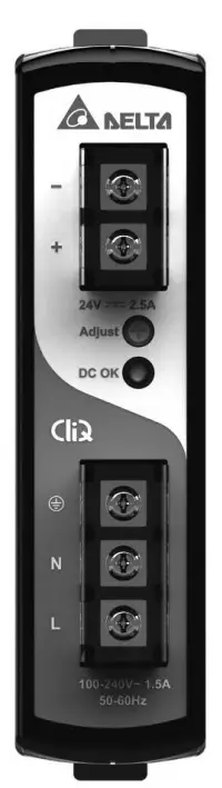
DELTA DRP024V060W1AZ CliQ Power Supply System
Safety instructions
- Switch main power off before connect or disconnect the device. Danger of explosion!
- To guarantee sufficient convection cooling, please keep a distance of 50mm above and below the device as well as a lateral distance of 20mm to other units.
- Please note, that the enclosure of the device can become very hot depending onthe ambient temperature and load of the power supply. Risk of burns!
- Only plug in and unplug connectors when power is turned off!
- Do not introduce any objects into the unit!
- Dangerous voltage is present for at least 5 minutes after disconnecting all sources of power.
Device description
(Fig. 1)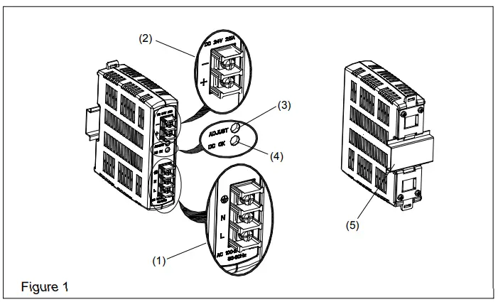
- Input terminal block connector
- Output terminal block connector
- DC voltage adjustment potentiometer
- DC OK control LED (green)
- The universal mounting rail system
Mounting (Fig. 2)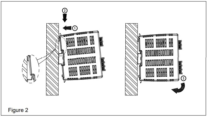
- The power supply unit can be mounted on 35mm DIN rails in accordance with EN60715. The device should be installed with an input terminal block on the bottom.
Each device is delivered and ready to install.
Snap-on the DIN rail as shown in Fig. 2:
- Tilt the unit slightly upwards and put it onto the DIN rail.
- Push downwards until stopped.
- Press against the bottom front side for locking.
- Shake the unit slightly to ensure that it is secured.
- Dismounting (Fig. 3)

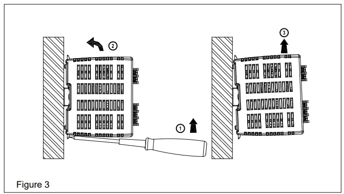
To uninstall, pull or slide down the latch as shown in Fig. 3. Then, slide the PSU in the opposite direction, release the latch, and pull out the PSU from the rail.
Connection
- The terminal block connectors allow easy and fast wiring. A plastic cover provides the necessary isolation of the electric connection.
- You can use flexible (stranded wire) or solid cables with cross sections 0.52-2.1mm² (AWG 20-14) and torque of 0.78-0.98Nm (6.94-8.68lb in). To secure reliable and shockproof connections, the stripping length should be 7 mm.
- In accordance with EN60950 / UL60950 and EN62368 / UL62368, flexible cables require ferrules. Use appropriate copper cables that are designed to sustain an operating temperature of at least 75°C or more to fulfill UL requirements.
- For stranded wires, it is recommended to use a suitable lug to crimp wires (see Fig. 4).


Input connection (Fig. 1, Fig. 5)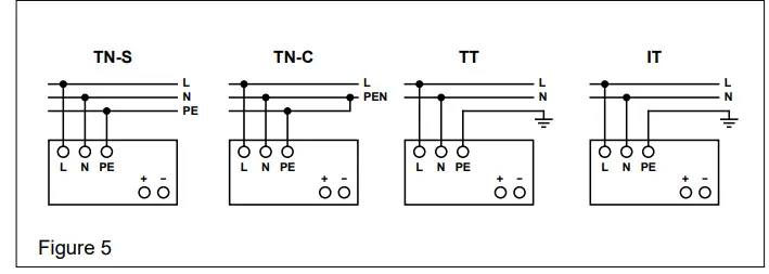
- Use L, N, and PE connections of the input terminal connector (see Fig. 1 (1)) to establish the 100-240Vac connection.
- The unit is protected with an internal fuse (not replaceable) at the L pin and it has been tested and approved on 20A (UL) and 16A (IEC) branch circuits without an additional protection device. An external protection device is only required if the supplying branch has an ampacity greater than above. Thus, if an external protective device is necessary, or, utilized, a minimum value of 20A B- or 13A C- characteristic breaker should be used.
- The internal fuse must not be replaced by the user.
- In case of an internal defect, return the unit for inspection to the manufacturer.
Output connection (Fig. 1 (2))
- Use the “+” and “-“ screw connections to establish the 24Vdc connection. The output provides 24Vdc. The output voltage can be adjusted from 22 to 28Vdc on the potentiometer. The green LED DC OK displays the correct function of the output (Fig. 1 (4)). The device has a short circuit and overload protection and an over voltage protection limited to 35Vdc.
Output characteristic curve
- The device functions normally under the operating line and load conditions. In the event of a short circuit or over load the output voltage and current collapses (IO/L or IS/C is > Isurge (150%)). The secondary voltage is reduced and bounces until short circuit or overload on the secondary side has been removed.
Thermal behavior (Fig. 6)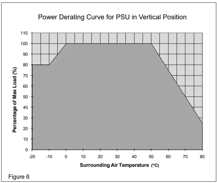
- In the case of ambient temperatures above +50°C, the output capacity has to be reduced by 2.5% per degree Celsius increase in temperature. If the output capacity is not reduced when TAmb > 50°C device will run into thermal protection by switching off i.e. device will go in bouncing mode and will recover when ambient temperature is lowered or the load is reduced as far as necessary to keep device in working condition.
Technical data
| Input (AC) | |
| Nominal input voltage | 100-240Vac |
| Voltage range | 85-264Vac (DC input range 120-375Vdc) |
| Frequency | 47-63Hz (0Hz @ DC input) |
| Nominal current | < 1.10A @ 115Vac, < 0.70A @ 230Vac |
| Inrush current limitation (+25°C, cold start) | < 40A @ 115Vac, < 80A @ 230Vac |
| Hold-up time | > 20ms @ 115Vac, > 125ms @ 230Vac |
| Start-up time | < 3 sec. |
|
Internal fuse | T 3.15 AH / 250V Min. – Bel (Type 5HT/5HTP) – Littelfuse (Type 215 or 477) – Schurter (Type SPT) – Wickmann (Type 181) – Conquer (Type UDE, UDE-A)
F 3.15 AH / 250V Min. – Dongguan Better (Type 513 or 531)
T 3.15 A Enhanced Breaking / 250V Min. – Dongguan Better (Type 582) |
| Leakage current | < 1mA @ 240Vac |
| Output (DC) | |
| Nominal output voltage UN/tolerance | 24Vdc ± 2% |
| The adjustment range of the voltage | 22-28Vdc |
| Nominal current | 2.5A |
| Derating above +50°C | 2.5% / °C (< 0°C 2% / °C) |
| Startup with capacitive loads | Max. 8,000µF |
| Max. power dissipation idling / nominal load approx. | 10W |
| Efficiency | > 86.0% @ 115Vac, > 87.0% @ 230Vac |
| Residual ripple/peak switching (20MHz) (at nominal values) | < 50mVpp / < 240mVpp |
| Parallel operation | DRR-20¨ / DRR-40¨ / With ORing Diode |
| General Data | |
| Type of housing | Plastic (PC), closed |
| Signals | Green LED DC OK |
| MTBF | > 800,000 hrs. |
| Dimensions (L x W x D) | 121mm x 32mm x 113mm |
| Weight | 0.33kg |
| Connection method | Screw connection |
| Stripping length | 7mm or use a suitable lug to crimp |
| Operating temperature (Surrounding Air Temperature) | -20°C to +80°C (> 50°C derating) |
| Storage temperature | -25°C to +85°C |
| Humidity at +25°C, no condensation | < 95% RH |
| Vibration (non-operating) | 10 to 150Hz, 0.35mm acc. 50m/S², single amplitude (5G max.) for 90min. in each X, Y & Z directions, in acc. with IEC60068-2-6 |
| Shock (non-operating, in all directions) | 30G (300m/S²) in all directions according to IEC60068-2-27 |
| Pollution degree | 2 |
| Climatic class | 3K3 according to EN60721 |
| Safety and Protection | |
| Transient surge voltage protection | VARISTOR |
| Current limitation at short-circuits approx. | Isurge = 150% of Pomax typically |
| Surge voltage protection against internal surge voltages | Yes |
| Isolation voltage: Input/output (type test/routine test) Input / PE (type test/routine test) Output / PE (type test/routine test) | 4.0KVac / 3.0KVac 1.5KVac / 1.5KVac 1.5KVac / 0.5KVac |
| Protection degree | IPX0 |
| Safety class | Class I with PE connection |
The device must be installed by qualified persons only and in accordance with specific national regulations (e.g. VDE, DIN, etc.). Before installing this unit, read these operating and installation instructions carefully and completely.
- www.DeltaPSU.com
- Delta Electronics (Thailand) Public Company Limited
- 909 Moo 4, E.P.Z., Bangpoo Industrial Estate,
- Tambon Prakasa, Amphur Muang Samutprakarn,
- Samutprakarn 10280, Thailand.
- Tel: (662) 709-2800
- Fax: (662) 709-2827
- E-mail: [email protected]
- Call +1(800)985-6929 To Order or Order Online At Deltaacdrives.com


