
FERM INDUSTRIAL HDM1049P Demolition Hammer Instruction Manual
Thank you for buying this FERM product. By doing so you now have an excellent product, delivered by one of Europe’s leading suppliers. All products delivered to you by Ferm are manufactured according to the highest standards of performance and safety. As part of our philosophy we also provide an excellent customer service, backed by our comprehensive warranty. We hope you will enjoy using this product for many years to come.
SAFETY WARNINGS
WARNING Read the enclosed safety warnings, the additional safety warnings and the instructions. Failure to follow the safety warnings and the instructions may result in electric shock, fire and/or serious injury. Save the safety warnings and the instructions for future reference.
The following symbols are used in the user manual or on the product:
- Read the user manual.

- Denotes risk of personal injury, loss of life or damage to the tool in case of nonobservance of the instructions in this manual.
- Risk of electric shock
- Immediately remove the mains plug from the mains if the mains cable becomes damaged and during cleaning and maintenance.
- Always wear eye protection!
- Wear hearing protection.
- Wear a dust mask

- Wear safety gloves.

- Do not dispose of the product in unsuitable containers.

- The product is in accordance with the applicable safety standards in the European directives.


Additional safety warnings for demolition hammer
- a) Wear ear protectors. Exposure to noise can cause hearing loss.
- b) Use auxiliary handle(s), if supplied with the tool. Loss of control can cause personal injury.
- c) Hold power tool by insulated gripping surfaces, when performing an operation where the cutting accessory may contact hidden wiring or its own cord. Cutting accessory contacting a “live” wire may make exposed metal parts of the power tool “live” and could give the operator an electric shock.
Electrical safety
When using electric machines always observe the safety regulations applicable in your country to reduce the risk of fire, electric shock and personal injury. Read the following safety instructions and also the enclosed safety instructions.
- Always check that the voltage of the power supply corresponds to the voltage on the rating plate label.
- Class II machine – Double insulation – You don’t need any earthed plug.
- If operating a power tool in a damp location is unavoidable, use a residual current device (RCD) protected supply. Use of an RCD reduces the risk of electric shock.


Replacement of power cords or plugs
If the supply cord is damaged, it must be replaced by the manufacturer, its service agent or similarly qualified persons in order to avoid a hazard.
Use of extension leads
Only ever use approved extension leads that are suitable for the power rating of the machine. The minimum core thickness is 1.5 mm2 . Whenever using a reel extension lead, always fully unroll the lead.
Immediately switch off the machine when:
- Excessive sparking of the carbon brushes.
- Interruption of the mains plug, mains lead or mains lead damage.
- Defect switch.
- Smoke or stench of scorched isolation
MACHINE INFORMATION
Intended use
The demolition hammer is intended for demolishing concrete, chiseling off concrete, grooving and bar cutting.
This machine can only be used with SDS-Max chisels.
Technical specifications | |
| Mains voltage | 220-240 V — |
| Mains frequency | 50 Hz |
| Power input | 1.500 W |
| Impact rate | 1.000-1.900/min |
| Impact energy | 6-25J |
| Weight | 10.69 kg |
| Sound pressure (LpA) | 102.13dB(A) K=3 dB(A) |
| Acoustic power (LwA) | 105dB(A) K=3 dB(A) |
| Vibration | |
| Main grip ah checi | 20.38nn/s2K=1.5nn/s2 |
| Auxiliary grip ahcheci | 19.61 m/s’ K=1.5m/s2 |
Vibration level
The vibration emission level stated in this instruction manual has been measured in accordance with a standardized test given in EN60745. It may be used to compare one tool with another and as a preliminary assessment of exposure to vibration when using the tool for the applications mentioned.
- Using the tool for different applications, or with different or poorly maintained accessories, may significantly increase the exposure level.
- The times when the tool is switched off or when it is running but not actually doing the job, may significantly reduce the exposure level.
Protect yourself against the effects of vibration by maintaining the tool and its accessories, keeping your hands warm and organizing your work patterns.
Description
Fig. A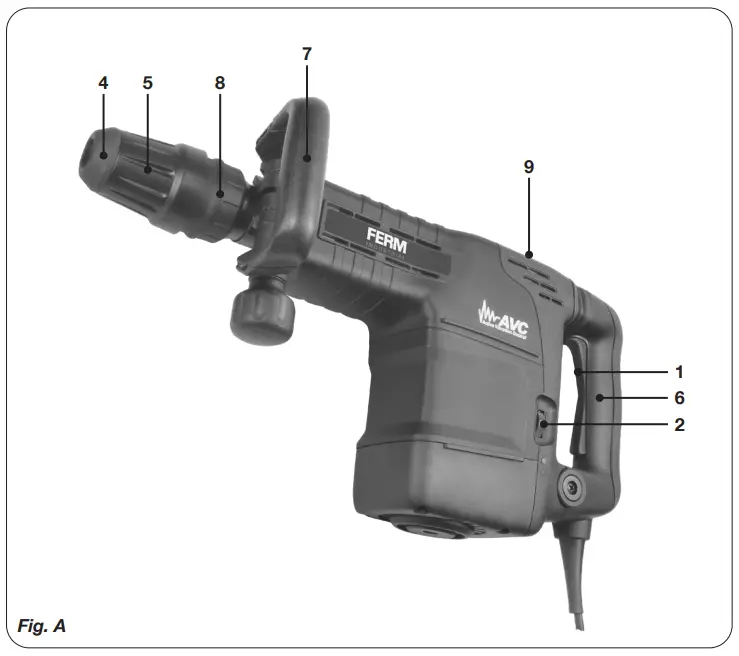
- On/off switch
- Speed adjustment wheel
- Chuck
- Locking sleeve
- Main grip
- Auxiliary grip
- Chisel position lock ring
- Lubrication point
ASSEMBLY
Before assembly, always switch off the machine and remove the mains plug from the mains.
Mounting and removing the accessory Fig. B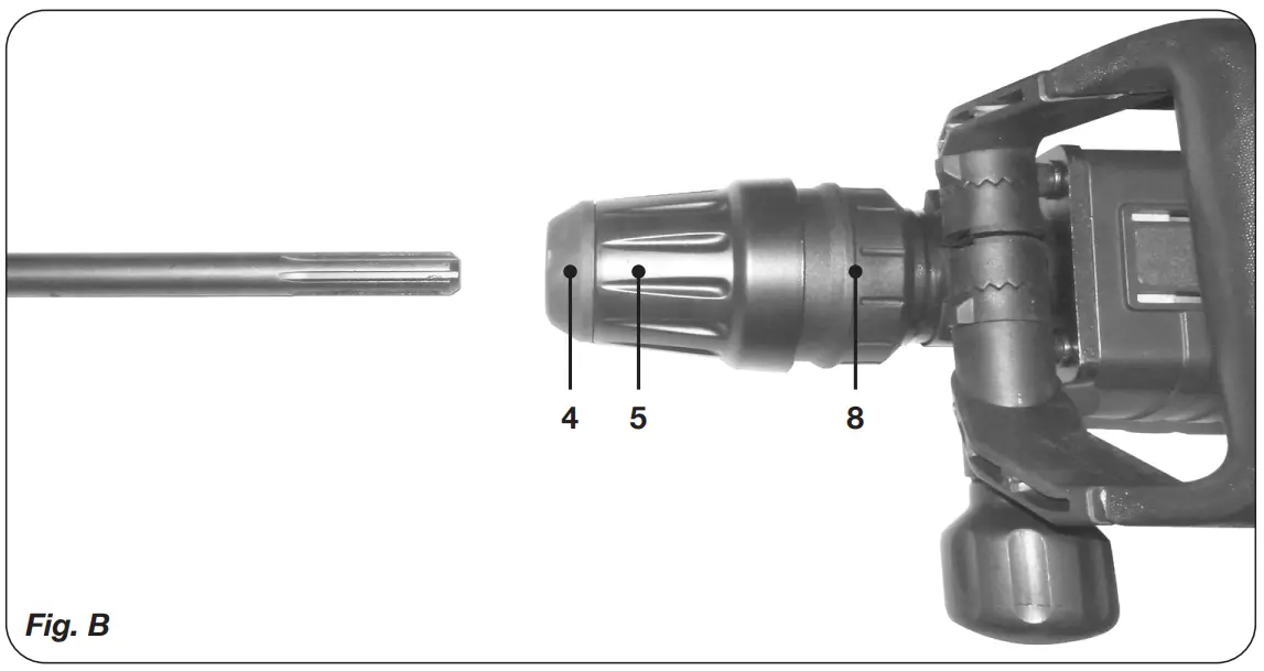
Do not use blunt drill bits or chisels. Immediately sharpen or replace blunt drill bits or chisels.
Mounting
- Apply a few drops of oil to the shaft of the accessory.
- Slide the locking sleeve (5) to the rear.
- Insert the accessory into the chuck (4).
- Release the locking sleeve (5).
Removing
- Slide the locking sleeve (5) to the rear.
- Remove the accessory from the chuck (4).
- Release the locking sleeve (5).
- Changing chisel position
- Push the lock ring (8) forward and turn the chisel to the desired position.
- Make sure the ring locks back in place before using the machine.
Setting the auxiliary grip
Fig. A
Mounting
- Loosen the auxiliary grip (7) by turning the knob counterclockwise.
- Turn the auxiliary grip (7) to the desired position.
- Tighten the auxiliary grip (7) by turning the knob clockwise.
USE
Switching On/Off Fig. A
- Switch the machine on by pressing the On/Off switch (1). When you release the On/Off switch (1) the machine will turn off.
Hints for optimum use
- Clamp the workpiece. Use a clamping device for small workpieces.
- Firmly hold the machine by the grip.
- Switch on the machine.
- Do not apply too much pressure on the machine. Let the machine do the work.
- Switch off the machine and wait for the machine to come to a complete standstill before putting the machine down.
CLEANING AND MAINTENANCE
Before cleaning and maintenance, always switch off the machine and remove the mains plug from the mains.
Clean the machine casings regularly with a soft cloth, preferably after each use. Make sure that the ventilation openings are free of dust and dirt. Remove very persistent dirt using a soft cloth moistened with soapsuds. Do not use any solvents such as gasoline, alcohol, ammonia etc. Chemicals such as these will damage the synthetic components.
Defects
The machine should be regularly inspected for the following possible defects and repaired if necessary.
- Damage to power cord.
- Broken on/off trigger assembly.
- Short circuiting.
- Damaged moving parts.
Faults
Should a fault occur, e.g. after wear of a part, please contact your seller or the service address on the warranty card. Separate you find an exploded view showing the parts that can be ordered.
WARRANTY
The warranty conditions can be found on the separately enclosed warranty card.
ENVIRONMENT
Faulty and/or discarded electrical or electronic apparatus have to be collected at the appropriate recycling locations.
Only for EC countries
Do not dispose of power tools into domestic waste. According to the European Guideline 2012/19/EC for Waste Electrical and Electronic Equipment and its implementation into national right, power tools that are no longer usable must be collected separately and disposed of in an environmentally friendly way.
The product and the user manual are subject to change. Specifications can be changed without further notice.
Spare parts list
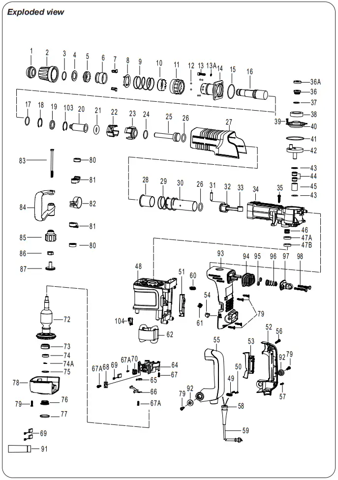
HDM1049P
| No | Description | Position |
| 411092 | Chuck cover set | 1..5 |
| 411093 | Hammer rod set | 7|12|16 |
| 411094 | Control sleeve set | 28|29 |
| 411095 | Oil cap set | 36|36A|37 |
| 411096 | Bottom cover set | 76..78 |
| 411097 | Side handle assembly | 80..84 |
| 411098 | Shock absorbtion set | 94..98 |
| 480711 | Rubber nose cap | 1 |
| 480712 | Protective sleeve | 2 |
| 480713 | Circlip 30 | 3 |
| 480714 | Filler ring | 4 |
| 480715 | Shock absorption ring | 5 |
| 480716 | Movement limiter | 6 |
| 480717 | Insert block (2pcs) | 7 |
| 480718 | Change plate | 8 |
| 480719 | Support ring spring | 9 |
| 480720 | Position lock ring | 10 |
| 480721 | Position adjustment ring | 11 |
| 480722 | Steel ball 6,5 (8pcs) | 12 |
| 480723 | Hex. Socket Bolt M8íŒ30 (4pcs) | 13 |
| 480724 | Spring washer 8 (4pcs) | 13A |
| 480725 | Flange cover | 14 |
| 480726 | O-Ring 63,5 * 2,6 | 15 |
| 480727 | Hammer rod sleeve | 16 |
| 480728 | O Ring 31.6íŒ2.5 | 17 |
| 480729 | Circlip 41 | 18 |
| 480730 | Oil Seal Ring 32x42x7 | 19 |
| 480731 | Impact Pin | 20 |
| 480732 | O Ring 22íŒ11 | 21 |
| 480733 | Control plate | 22 |
| 480734 | Fixed distance sleeve | 23 |
| 480735 | O ring 35×3 | 24 |
| 480736 | Impact block | 25 |
| 480737 | O ring 30,4×5 | 26 |
| No | Description | Position |
| 480738 | Cover | 27 |
| 480739 | Control Sleeve | 28 |
| 480740 | Control Sleeve Spring | 29 |
| 480741 | Cilinder | 30 |
| 480742 | Piston Pin 10*38 | 31 |
| 480743 | Piston | 32 |
| 480744 | Drive rod | 33 |
| 480745 | Gearbox | 34 |
| 480746 | Tapping screw ST6.3×32 | 35 |
| 480747 | Oil cap | 36 |
| 480748 | Cover | 36A |
| 480749 | Rubber Washer | 37 |
| 480750 | Felt Ring | 38 |
| 480751 | Hex .Socket Bolt M5íŒ12 | 39 |
| 480752 | Shell cover | 40 |
| 480753 | O-Ring 79íŒ2.8 | 41 |
| 480754 | Excentric gear | 42 |
| 480755 | Bearing 6002RS | 43 |
| 480756 | Distance Ring | 44 |
| 480757 | Bearing 6002RS | 45 |
| 480758 | Needle bearing | 46 |
| 480759 | Seal ring | 47 |
| 480760 | Motor housing | 48 |
| 480761 | Cord clamp | 49 |
| 480762 | Clamp crew | 50 |
| 480763 | Speed control | 51 |
| 480766 | Indicator light | 54 |
| 480768 | Screw | 56 |
| 480769 | Screw | 57 |
| 480770 | Cable sheath | 58 |
| 480771 | Cord | 59 |
| 480772 | Inductor | 60 |
| 480773 | Wire connector | 61 |
| 480774 | Stator | 62 |
| No | Description | Position |
| 480775 | Stator screw | 63 |
| 480776 | Carbon brush holder set (2pcs) | 64 |
| 480777 | Brush holder spring set (2pcs) | 65 |
| 480778 | Contact plate | 66 |
| 480779 | Screw | 67 |
| 480780 | Screw | 67A |
| 480781 | Insert | 68 |
| 480782 | Carbon Brush set (2pcs) | 69 |
| 480783 | Carbon brush wire set (2pcs) | 70 |
| 480784 | Rotor | 72 |
| 480785 | Bearing sleeve | 73 |
| 480786 | Bottom rotor bearing 6200RS | 74 |
| 480787 | Circlip 10 | 74A |
| 480788 | O-ring | 75 |
| 480789 | Screw ring | 76 |
| 480790 | Protecting cover | 77 |
| 480791 | Bottom Cover | 78 |
| 480792 | Screw | 79 |
| 480793 | Position ring 1 | 80 |
| 480794 | Position ring 2 | 81 |
| 480795 | Handle ring | 82 |
| 480796 | handle bolt | 83 |
| 480797 | Side Handle | 84 |
| 480798 | Clamping knob | 85 |
| 480799 | Nut | 86 |
| 480800 | Knob cover | 87 |
| 480801 | Hex key | 88 |
| 480802 | Oil bottle | 91 |
| 480803 | Main handle washer | 92 |
| 480804 | Back cover | 93 |
| 480805 | Vibration absorbing sleeve | 94 |
| 480806 | Vibration absorbing rings | 95 |
| 480807 | Vibration absorbing spring | 96 |
| 480808 | Vibration absorbing bracket | 97 |
| No | Description | Position |
| 480809 | Vibration absorbing screws | 98 |
| 481785 | Main handle right | 55 |
| 481786 | Main handle left | 52 |
| 481787 | Switch | 53 |
DECLARATION OF CONFORMITY
We declare under our sole responsibility that this product is in conformity with directive 2011/65/EU of the European parliament and of the council of 8 June on the restriction of the use of certain hazardous substances in electrical and electronic equipment is in conformity and accordance with the following standards and regulations.
EN 60745-1, EN 60745-2-6, EN 55014-1, EN 55014-2,
EN 61000-3-2, EN 61000-3-3
2006/42/EC, 2014/30/EU, 2011/65/EU, 2012/19/EC
Zwolle, 01-02-2021

H.G.F Rosberg CEO FERM


