![]() AK-RC 305W-SD Temperature Controller for
AK-RC 305W-SD Temperature Controller for
Walk-In Coolers and Freezers
Installation Guide

![]() Warnings
Warnings
- If the equipment is used without adhering to the manufacturer’s instructions, the device safety requirements could be compromised. Only probes supplied by Danfoss must be used for the unit to operate correctly.
- From -40 – +20 °C, if the NTC probe is extended to 1000 m with at least 0.5 mm 2 cable, the maximum deviation will be 0.25 °C
- It should be installed in a place protected from vibrations, water and corrosive gases, where the ambient temperature does not exceed the value indicated in the technical data.
- For the reading to be correct, the probe should be used in a place without heat influences apart from the temperature you want to measure or control.
- The IP65 protection degree is only valid with the protection cover closed.
- The IP65 protection degree is only valid if the cables enter the device using a tube for electric conductions + gland with IP65 or above.
The size of the glands should be suitable for the diameter of the tube used. - Do not spray the unit directly with high-pressure hoses, as this could cause damage.
IMPORTANT:
- Before starting the installation, you must take the advice of local regulations in force.
- The AUXILIARY relays are programmable, and their operation depends on the configuration.
- The function of the digital inputs depends on the configuration.
- The recommended currents and powers are the maximum working currents and powers.
Wiring![]() Always disconnect the power supply to do the wiring.
Always disconnect the power supply to do the wiring.
The probes and their cables should NEVER be installed in a conduit together with power, control, or power supply cables.
For disconnection, the power supply circuit must be equipped with at least a 2 A, 230 V switch, located near the device. The power supply cable shall be of the H05VV-F or NYM 1×16/3 type. The cross-section to be used will depend on the local regulations in force, but must never be less than 1.5 mm 2.
Cables for relay or contactor outputs must have a cross-section of 2.5 mm 2 and allow working temperatures equal to or over 70 °C and must be installed with as little bending as possible.
The 120/230 V~ wiring area must be kept clear of any other external element.
The wiring to be undertaken depends on the option selected in the initial configuration wizard. Use the appropriate diagram based on the option selected. Check the available options on the diagrams included in the controller’s packaging. Wizard refers to a built-in tool to guide the user through the setup process.
Maintenance
- Clean the surface of the unit with a soft cloth, water, and soap.
- Do not use abrasive detergents, petrol, alcohol, or solvents, as this might damage the unit.
Keypad
 | Pressing it for 3 seconds activates/deactivates Stand-By mode. In this mode, regulation is paused and the In the programming menu, this exits the parameter without saving changes, returns to the previous level, or exits programming. |
 | Pressing once without holding displays the temperature of probe S2 for 2 seconds (if it is enabled). Pressing it for 3 seconds starts/stops the defrost. In the programming menu, this allows scrolling around the different levels, or, during the setting of a parameter, changing its value. |
 | A brief press shows the ADAPTIVE mode operating alerts. Pressing it for 3 seconds activates/deactivates continuous cycle mode. In the programming menu, this allows scrolling around the different levels, or, during the setting of a parameter, changing its value. |
 | Pressing once without holding activates/deactivates the cold room light. Pressing it for 3 seconds accesses the condensed programming menu. Pressing it for 6 seconds accesses the expanded programming menu. In the programming menu, this accesses the level shown on the display or, during the setting of a parameter, accepts the new value. |
 | Pressing once without holding displays the current effective value of the Set Point, taking into consideration temporary modifications by other parameters (C10 or C12). When an alarm is in progress, pressing once without holding mutes the acoustic alarm. Pressing for 3 seconds accesses the Set Point setting. |
Indicators
| Fixed: Stand-by Mode activated. Regulation is paused. Flashing: Controlled shutdown process for the regulation in progress. | |
| Fixed: Cold room door open. Flashing: The door has been open for a greater time than has been defined in parameter A12. | |
| There is an active alarm, but not an active HACCP alarm. | |
| Fixed: HACCP alarm active. Flashing: HACCP alarm registered and unconfirmed. Press the | |
| Fixed: The ADAPTIVE mode is active. Flashing: An error has been detected in the ADAPTIVE mode. | |
 | Fixed: Evaporator fans active. Flashing: The evaporator fans should be active but a delay is preventing this. |
 | Fixed: The cold solenoid is active. Flashing: The solenoid should be active but a delay or protection is preventing this. |
| Fixed: Compressor active. Flashing: The compressor should be active but a delay or protection is preventing this. | |
 | Defrost relay active. |
 | Continuous cycle mode is active. |
| Cold room light active. | |
| The alarm in progress is muted. | |
| °F°C | Temperature displayed in ° Fahrenheit / ° Centigrade. |
| PRG | Programming mode active. |
STAND-BY![]() If the temperature regulation cannot be instantly stopped due to its configuration, a controlled stop process starts, and the
If the temperature regulation cannot be instantly stopped due to its configuration, a controlled stop process starts, and the![]() icon flashes. To stop the controlled stop process and force the step to Stand-by, press the Stand-by key again for 3 seconds.
icon flashes. To stop the controlled stop process and force the step to Stand-by, press the Stand-by key again for 3 seconds.
Installation of the probes
To achieve maximum performance from the advanced controller, the correct installation of the probes is key, as they are responsible for calculating the evaporator’s thermal transfer coefficient, evaluating the start and end of the defrosts, and diagnosing problems in the evaporator.
Material included
- 4 mm hermetic evaporator probe, 1.5 m of cable.
- Ambient probe
- 1 mounting clip for 10 – 13 mm coil
- 1 mounting clip for 14 – 18 mm coil
- 1 mounting clip for 19 – 21 mm coil
- 1 mounting clip for 22 – 25 mm coil
Location of the ambient probe
The probe should be located in a place that does not directly receive the flow of cold air from the evaporator.
Preferably in its air aspiration area.
Location of the evaporator probe
The probe must be located as near as possible to the inlet of refrigerant from the evaporator (close to the expansion valve) in the finned area. In certain evaporators, for example, cubic ones, this inlet may be located on the front part of the battery, just behind the fan.
If defrosting is done by electric heat, the probe must be located far away from them and, if possible, in the area of the evaporator where defrosting is slower, in other words, in the last area to defrost.
If the two conditions are not possible, the best possible compromise must be looked for.
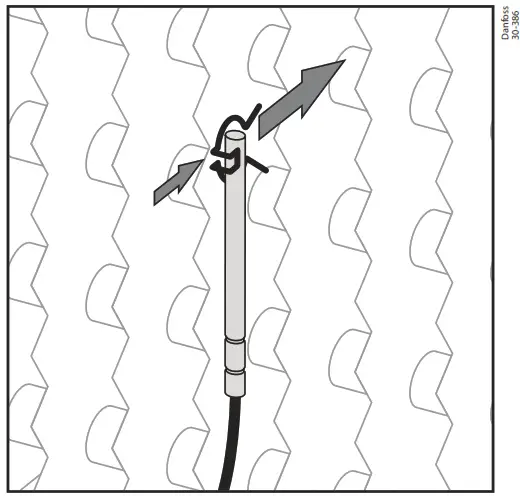 | 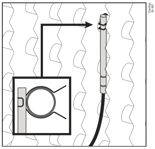 | 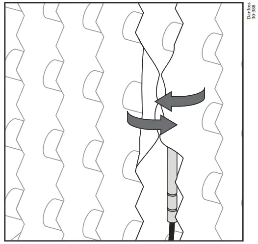 |
| Select the appropriate clip depending on the size of its evaporator pipe. | Attach the probe to the pipe using the clip, making sure that its end is in direct contact with the tube. | Bend the fins of both ends of the probe to increase the fixing and contact surface. |
Initial configuration (wizard)
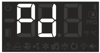
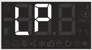
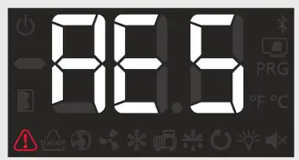
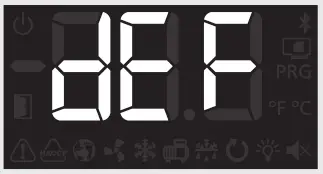
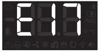
The first time the unit receives the power supply, it will enter into ASSISTANT mode. The display will show the message![]() flashing with 0.
flashing with 0.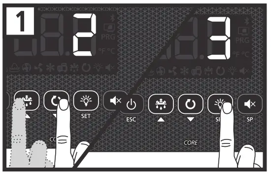
Step 1:
Select the most suitable InI option based on the type of installation to be carried out and press SET. The available options will be shown in the following table:
| Inl | Type of installation | Parameters | Diagram to be used | ||||||||||||
| Cold regulation | Pump Down | Defrost | Evap. fans | Pd | o00 | 100 | 110 | 111 | 120 | 121 | dl | d7 | F3 | ||
| 0 | Demo Mode: it displays the temperature but does not regulate the temperature or activate relays | ||||||||||||||
| 1 | Solenoid | No | Electric | Yes | 0 | 0 | 2 | 0 | 0 | 0 | 0 | 20 | 0 | 0 | A |
| 2 | Solenoid + compressor | Yes | Electric | Yes | 1 | 1 | 2 | 7 | 1 | 0 | 0 | 20 | 0 | 0 | B |
| 3 | Solenoid + compressor | No | Electric | Yes | 0 | 1 | 2 | 0 | 0 | 0 | 0 | 20 | 0 | 0 | B |
| 4 | Solenoid | No | Air | Yes | 0 | 0 | 1 | 0 | 0 | 0 | 0 | 20 | 1 | 1 | A |
| 5 | Solenoid + compressor | Yes | Air | Yes | 1 | 1 | 1 | 7 | 1 | 0 | 0 | 20 | 1 | 1 | B |
| 6 | Solenoid + compressor | No | Air | Yes | 0 | 1 | 1 | 0 | 0 | 0 | 0 | 20 | 1 | 1 | B |
| 7 | Solenoid + compressor | Yes | Hot gas | Yes | 1 | 1 | 2 | 7 | 1 | 9 | 1 | 5 | 2 | 0 | C |
| 8 | Solenoid + compressor | No | Hot gas | Yes | 0 | 1 | 2 | 0 | 0 | 9 | 1 | 5 | 2 | 0 | C |
Note: If options 2, 5, or 7 are chosen, check the configuration of parameter I11 according to the pressure switch type used. (See diagram included with the device).
Step 2:
Use keys![]() and
and![]() to enter the desired Temperature Set Point value and press SET. The configuration wizard has finished. The unit will begin to regulate the temperature.
to enter the desired Temperature Set Point value and press SET. The configuration wizard has finished. The unit will begin to regulate the temperature.
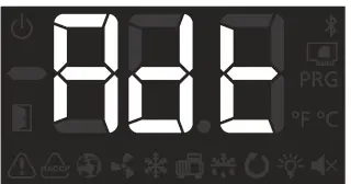
If this is not the first time you use the wizard, after completing the last step the display will show the message dFp (default parameters). You may choose between two options:
0: Only changing the parameters which affect the wizard. The other parameters will remain the same.
1: All parameters return to their factory setting except those which have been modified by the wizard.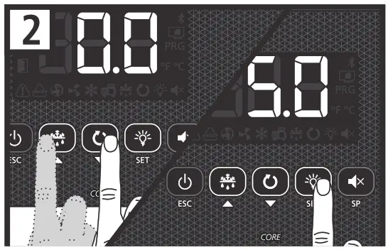 Important: The wizard will not reactivate. To enter the wizard mode, initiate Stand-by mode by pressing the key for 3 seconds and wait until the unit completely halts the temperature regulation (the indicator will light up permanently) and press the following keys in sequence one after the other,
 ![]() ,
, ![]() , SET.
, SET.![]() Stand-by: If the regulation cannot be instantly stopped due to its configuration, a controlled stop process starts and the icon flashes.
Stand-by: If the regulation cannot be instantly stopped due to its configuration, a controlled stop process starts and the icon flashes.
To stop the controlled stop process and force the step to Stand-by, press the Stand-by key again for 3 seconds.
Operation
Display messages
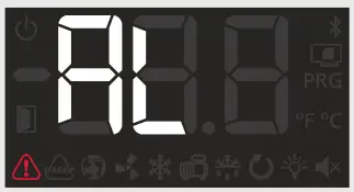
 | Pump down malfunction error (stop), the time configured in parameter C20 has been exceeded. Only displayed on the screen. |
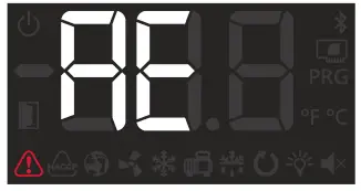
 | Pump down malfunction error (start-up), the time configured in parameter C19 has been exceeded. Only displayed on the screen. |
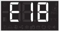
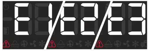 | Probe 1/2/3 failure (open circuit, crossed circuit, or temperature outside the limits of the probe) (Equivalent limits in °F). Only E2 and E3: Damp evaporator probe. Activates the alarm relay and the audible alarm. Flashing with temperature: Probe error 1/2/3 in ADAPTIVE mode. Flashing with CAL: Probe error 1/2/3 during the calibration. |
 | Open door alarm. Only if the door remains open for a longer time than defined in parameter A12. Activates the alarm relay and the audible alarm. |
 | Maximum temperature in control probe alarm. The temperature value programmed in A1 has been reached. Activates the alarm relay and the audible alarm. |
 | The minimum temperature in the control probe alarm. The temperature value programmed in A2 has been reached. Activates the alarm relay and the audible alarm. |
 | External alarm activated (by digital input). Activates the alarm relay and the audible alarm. |
 | Severe external alarm activated (by digital input). Activates the alarm relay and the audible alarm. |
 | The alarm for defrosting was completed due to a time-out. The time set in d1 has been exceeded. Activates the alarm relay and the audible alarm. |
 | HACCP alarm. The temperature has reached the value of parameter h1 during a longer period than established in h2. Activates the alarm relay and the audible alarm. |
 | HACCP alarm due to a power supply failure. The temperature established in h1 has been reached, following a power supply failure. Activates the alarm relay and the audible alarm. |
 | Indicates that a defrost is being performed. Only displayed on the screen. |
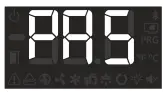 | Password request. See parameters b10 and PAS. Only displayed on the screen. |
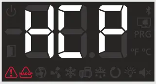
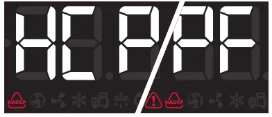
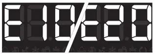
 | Shown sequentially with the temperature: The controller is in demo mode, and the configuration has not been made. |
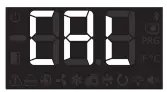 | Calibration is ongoing, therefore, avoid, as far as possible, opening the cold room during the process. |
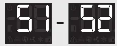
 | Flashing with temperature: Configuration has been changed from 1 to 2 evaporators or vice versa. |
ADAPTIVE MODE ALERT MESSAGES (Only shown pressing the![]() key)
key)
 | Defrost end error in the 1/2 evaporator during the calibration, defrost has not ended due to temperature. |
 | Error during calibration in 1/2 evaporator. There is not enough difference in temperature between the cold room probe and the evaporator probe. |
 | It has not been possible to carry out the calibration due to a lack of stability in the system (Excessive door opening, excessive oscillations in the lower pressure, etc.). |
 | Error during normal operation (ADAPTIVE Mode active) in 1/2 evaporator. There is not enough difference in temperature between the cold room probe and the evaporator probe. |
 | A lack of stability has been detected in the system (Excessive door opening, excessive oscillations in the low pressure, etc.) during normal operation (ADAPTIVE Mode active). |
 | The persistent lack of stability has led to the deactivation of the ADAPTIVE mode. |
 | Excessive door openings have been detected during calibration and it has not been possible to calibrate. |
 | Excessive door openings have been detected and the device cannot regulate in ADAPTIVE mode. |
![]() ADAPTIVE mode
ADAPTIVE mode
If the ADAPTIVE mode is activated (default configuration), the device periodically evaluates the evaporator’s heat transfer, managing the available resources to maximize it.
The defrosts are minimized, adapting to the changing conditions of the cold room, reducing heat input into the refrigerated space, thermal stress in the evaporator, and energy consumption.
Operation of the evaporate fans is optimized taking into account the compressor status, evaporate temperature, frost level, the opening of the door, etc.
The control function of the drainage resistor minimizes its activation (moments before starting a defrost), thereby reducing energy consumption.
To achieve correct operation of the ADAPTIVE mode, it is very important for the probes to be correctly installed, as described on page 3.
Calibration
During the first hours of operation, the device performs two calibrations automatically, during which the display shows the CAL message.
Calibration may take several hours and include several refrigerations and defrost cycles.![]() During the calibration processes, the following should be avoided:
During the calibration processes, the following should be avoided: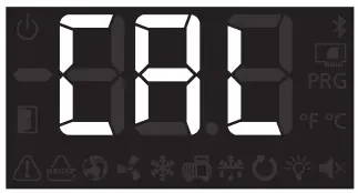
- Opening the cold room door
- Turning the controller off or putting it on standby
- Changing controller parameters, including the set point
IMPORTANT:
While the calibration process is active:
- Manual defrost cannot be activated (
 key)
key) - The continuous cycle cannot be activated
- The set point change function cannot be activated
If calibration cannot be performed, or if an important part of the installation is replaced (compressor, evaporator, etc.) it is advisable to perform a manual calibration.
It is also recommended (not essential) to perform a manual calibration, once the installation has completed its commissioning, with a load inside it and when its operating temperature has been stabilized, after several days of operation, in this way calibration is optimal.
In the event of changing the set point or hysteresis, the device performs a calibration again automatically, except if the set point change is made using the “set point change mode” function.
To perform a manual calibration, access the parameter menu and follow the sequence indicated below:
- Access parameter b30
- A security code is requested, enter code 63
- Using keys
 and
and  select option 1 and press SET
Configuration
Condensed programming menu
This allows for the most-used parameters to be quickly configured.
Press the SET key for 3 seconds to access it.
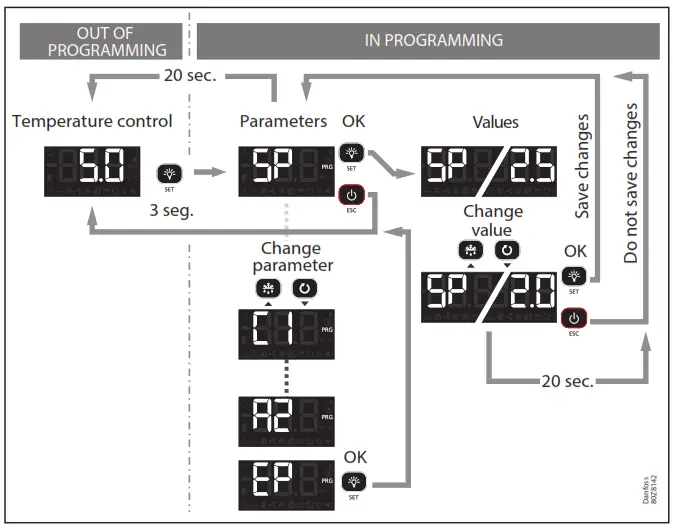
Parameters
| Lv 2 | Description | Val. | Min. | Def. | Max. |
| SP | Temperature setting (Set Point) | °C/°F | -50 | 0.0 | 99 |
| CE | ADAPTIVE Mode O=Deactivated, 1= Activated | 0 | 1 | 1 | |
| Cl | Probe 1 differential (Hysteresis) | °C/°F | 0.1 | 2.0 | 20.0 |
| dO | Defrost frequency (Time between 2 starts) | H. | 0 | 6 | 96 |
| d 1 | Maximum defrost duration (0=defrost deactivated) | Min. | 0 | * | 255 |
| d4 | Final defrost temperature (by the probe) (If P4 #1) | °C/°F | -50 | 8.0 | 50 |
| F3 | Status of the fans during the defrost: O=Shut down, 1=Running | 0 | 0 | 1 | |
| Al | Alarm for the maximum in probe 1 (It should be higher than the SP) | °C/°F | A2 | 99 | 99 |
| A2 | Alarm for minimum in probe 1 (It should be lower than the SP) | 0C/7 | -50 | -50 | Al |
| d30 | Defrost strategy in ADAPTIVE mode | 0 | 5 | 10 |
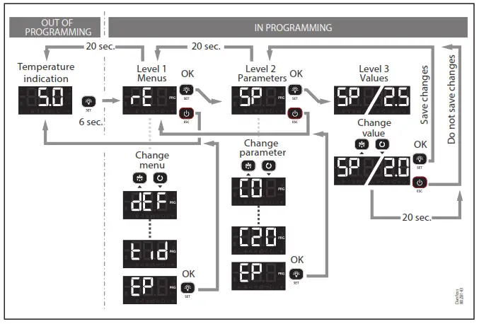
Extended programming menu
Use the extended programming menu to configure all of the unit’s parameters in order to adapt it to your installation requirements.
Press the SET key for 6 seconds to access it.
Important:
- If the password function has been configured as a keypad lock (b10=2), or as access to parameters block (b10=1), you will be requested to enter the password programmed in PAS when attempting to access either of the two functions. If the entered password is not correct, the unit will go back to showing the temperature.
- Certain parameters or menus may not be visible depending on the configuration of the rest of the parameters.

Regulation and control
| Level 1 | Level 2 | Description | Values | Min. | Def. | Max. |
| rE | SP | Temperature setting (Set Point) | °C/°F | -50 | 0.0 | 99 |
| CE | ADAPTIVE Mode: 0=Deactivated, 1= Activated | 0 | 1 | 1 | ||
| CO | Probe 1 & 2 calibration (Offset) | °C/°F | –4.0 | 0.0 | 4.0 | |
| Cl | Probe 1 differential (Hysteresis) | °C/°F | 0.1 | 2.0 | 20.0 | |
| C2 | Set Point top locking (it cannot be set above this value) | °C/°F | C3 | 99 | 99 | |
| C3 | Set Point bottom locking (it cannot be set below this value) | °C/°F | -50 | -50 | C2 | |
| C4 | Type of delay for the protection of the compressor: 0=Minimum time of compressor in OFF 1=Minimum time of compressor in OFF and in ON in each cycle | 0 | 0 | 1 | ||
| CS | Protection delay time (value of the option selected in parameter C4) | Min. | 0 | 0 | 120 | |
| C6 | COOL relay status with fault in probe 1: 0=OFF; 1=0N; 2=Average according to last 24 h prior to probe error 3=0N-OFF according to prog. C7 and C8 | 0 | 2 | 3 | ||
| C7 | Relay time in ON in the event of probe 1 failure (If C7=0 and C8*0, the relay will always be disconnected in OFF) | Min. | 0 | 10 | 120 | |
| CS | Relay time in OFF in the event of probe 1 failure (If C8=0 and C70, the relay will always be connected in ON) | Min. | 0 | 5 | 120 | |
| C9 | Maximum duration of the continuous cycle mode (0=deactivated) | H. | 0 | 0 | 48 | |
| C10 | Variation of the Set Point (SP) in continuous cycle mode. When it reaches this point (SP+CI 0), it reverts to the normal mode. (SP+CI 0 a C3). The value of this parameter is always negative unless it is O. (0=OFF) | °C/°F | 0 | -50 | C3-SP | |
| CU | Variation of the Set Point (SP) when the change Set Point function is active. (SP+C12 s C2) (0= deactivated) | °C/°F | C3-SP | 0.0 | C2-SP | |
| C19 | Maximum start time from Pump Down (Values between 1 and 9 seconds will not be accepted) (0=deactivated) | Sec | 0 | 0 | 120 | |
| C20 | The maximum time for pump down (0= deactivated) | Min. | 0 | 0 | 15 | |
| C21 | Probe to be displayed: 0=All probes (sequential), 1=Probe 1 (Cold Room), 2=Probe 2 (Evaporator), 3= Probe 3 (According to 120), 4=Weighted temperature of the cold room | 0 | 1 | 3 | ||
| C22 | Stop fans and compressor on opening door 0=No, 1=Yes | 0 | 0 | 1 | ||
| C23 | Start-up delay for fans and compressor with the door open | Min. | 0 | 0 | 999 | |
| C24 | Delay time of cold stop with the door open. | Seg. | 0 | 0 | C23 | |
| C25 | Influence of probe S3 when regulating with two temperature probes (120=10) | % | 0 | 0 | 95 | |
| C27 | Probe 3 calibration (Offset) | °C/°F | –4.0 | 0.0 | 4.0 | |
| EP | Exit to level 1 |
Defrost
| Level 1 | Level 2 | Description | Values | Min. | Def. | Max. |
| dEF | dO | Defrost frequency (Time between 2 starts) | H. | 0 | 6 | 96 |
| dl | Maximum defrost duration (0=defrost deactivated) | Min. | 0 | 255 | ||
| d2 | Type of message during the defrost: O=Displays the real temperature; 1=Displays the temperature at the start of the defrost; 2=Displays the dEF message | 0 | 2 | 2 | ||
| d3 | The maximum duration of the message (lime added at the end of the defrost process) | Min. | 0 | 5 | 255 | |
| d4 | Final defrost temperature (by the probe) (If 100 * 1) | °C/°F | -50 | 8.0 | 50 | |
| d5 | Defrost on connecting the unit: O=NO First defrost according to d0; 1=YES, First defrost according to d6 | 0 | 0 | 1 | ||
| d6 | Delay of the defrost start on connecting the unit | Min. | 0 | 0 | 255 | |
| dr | Type of defrosting: 0=Resistors; 1=Air/fans, 2=Hot gas; 3=Reversal of cycle | 0 | 3 | |||
| d8 | Count of time between defrost periods: Total real-time, 1 =Sum of compressor connected time | 0 | 0 | 1 | ||
| d9 | Drip time when completing defrost (Shutdown of compressor and fans) | Min. | 0 | 1 | 255 | |
| d30 | Defrost strategy in ADAPTIVE mode | 0 | 5 | 10 | ||
| d31 | Maximum time without defrosting (O=Deactivated) | H. | 0 | 96 | 999 | |
| d32 | Maximum time of cold room outside the temperature regulation range (O=Deactivated) | H. | 0 | 2 | 10 | |
| EP | Exit to level 1 |
* According to the wizard.
1) It can only be modified using the configuration wizard (InI).
Evaporator fans
| Level 1 | Level 2 | Description | Values | Min. | Def. | Max. |
| FAn | FO | Shutdown temperature of fans | °C/°F | -50 | 45 | 50 |
| Fl | Probe 2 differential if fans are shut down | °C/°F | 0.1 | 2.0 | 20 | |
| F2 | Shut down fans when the compressor shuts down: 0=No, 1=Yes | 0 | 0 | 1 | ||
| F3 | Status of the fans during the defrost: 0=Shut down, 1=Running | 0 | 0 | 1 | ||
| F4 | Delay of start-up after defrost (If F3=0) It will only actuate if it is higher than d9 | Min. | 0 | 2 | 99 | |
| EP | Exit to level 1 |
Alarms
| Level 1 | Level 2 | Description | Values | Min. | Def. | Max. |
| AL | AO | Configuration of the temperature alarms: O=Relative to SR 1=Absolute | 0 | 1 | 1 | |
| Al | Alarm for the maximum in probe 1 (It should be higher than the SP) | °C1°F | A2 | 99 | 99 | |
| A2 | Alarm for minimum in probe 1 (It should be lower than the SP) | °C/°F | -50 | -50 | Al | |
| A3 | Delay of temperature alarms in the start-up | Min. | 0 | 0 | 120 | |
| A4 | Delay of temperature alarms from the end of a defrost | Min. | 0 | 0 | 99 | |
| AS | Delay of temperature alarms from when the Al or A2 value is reached | 0 | 30 | 99 | ||
| A6 | Delay of the external alarm/Severe external alarm on receiving a signal in digital input (110 or 120 = 2 or 3) | Min. | 0 | 0 | 120 | |
| A7 | Delay of external alarm deactivation/Severe external alarm deactivation when the signal in digital input disappears (110 or 120 = 2 or 3) | Min. | 0 | 0 | 120 | |
| A8 | Show warning if the defrost ends for maximum time: 0=No, 1=Yes | 0 | 0 | 1 | ||
| A9 | Relay alarm polarity 0= Relay ON in alarm (OFF without alarm); 1= Relay OFF in alarm (ON without alarm) | 0 | 0 | 1 | ||
| Al 0 | The differential of temperature alarms (Al and A2) | °C/°F | 0.1 | 1.0 | 20.0 | |
| Al2 | Delay of open door alarm (If 110 or 120=1) | Min. | 0 | 10 | 120 | |
| EP | Exit to level 1 |
Basic configuration
| Level 1 | Level 2 | Description | Values | Min. | Def. | Max. |
| BCN | b00 | Delay of all functions on receiving power supply | Min. | 0 | 0 | 255 |
| b01 | Cold room light timing | Min. | 0 | 0 | 999 | |
| b10 | Function of password 0=Inactive, 1=Block access to parameters, 2=Block keypad | 0 | 0 | 2 | ||
| PM | Access code (Password) | 0 | 0 | 99 | ||
| b20 | MODBUS address | 0 | 0 | 247 | ||
| b21 | Communication speed: 0=9600 bps, 1=19200 bps, 2=38400 bps, 3=57600 bps | bps | 0 | 2 | 3 | |
| b22 | Acoustic alarm enabled: 0= No, 1=Yes | 0 | 1 | 1 | ||
| b30 | Activation of manual calibration: 0=Deactivated, 1=Activated Requires security code, see page 6. | 0 | 0 | 1 | ||
| Unt | Work units: 0=°C, 1=°F | 0 | 1 | 1 | ||
| EP | Exit to level 1 |
Inputs and outputs
| Level 1 | Level 2 | Description | Values | Min. | Def. | Max. |
| In0 | 100 | Connected probes 1=Probe 1 (Cold room), 2=Probe 1 (Cold room) + Probe 2 (Evaporator) | 1 | 2 | 2 | |
| 110′) | Configuration of digital input 1 0= Deactivated, 1=Door contact, 2=External alarm, 3=Severe external alarm, 4=Change of SP, 5=Remote defrost, 6=Defrost block, 7= Low-pressure switch, 8=Remote Stand-by | 0 | 8 | |||
| Ill | The polarity of the digital input 1 0=Activates on closing contact; 1=Activates on opening contact | 0 | 1 | |||
| 120 | Configuration of digital input 2 0= Deactivated, 1=Door contact, 2=External alarm, 3=Severe external alarm, 4=Change of SP, 5=Remote defrost, 6=Defrost block, 7=Register probe, 8=Probe 2° evaporator”, 9=High pressure switch for Hot Gas, 10=2nd cold room temperature probe, 11=Product temperature, 12=Remote Stand-by | 0 | 0 | 12 | ||
| 121 | The polarity of the digital input 2 0=Activates on closing contact; 1=Activates on opening contact | 0 | 0 | 1 | ||
| 000¹) | Configuration of relay AUX1 0=Deactivated, 1=Compressor/Resistor sump, 2=Light. 3=Virtual control | 0 | 3 | |||
| ol 0 | Configuration of relay AUX2 0=Deactivated, 1=Alarm, 2=Light, 3=Virtual control, 4=Door frame resistance, 5=Defrost 2° evaporator, 6=Same as solenoid status, 7=Same as unit status, 8=Drainage resistor | 0 | 2 | 8 | ||
| EP | Exit to level 1 |
* According to the wizard.
- It can only be modified using the configuration wizard (InI).
- Option not available in AK-RC 305W-SD
HACCP alarm
| Level 1 | Level 2 | Description | Values | Min. | Def. | Max. |
| HCP | hl | Maximum temperature of HACCP alarm | °C/°f | -50 | 99 | 99 |
| h2 | Maximum permitted time for activation of the HACCP alarm (O=Disabled) | H. | 0 | 0 | 255 | |
| EP | Exit to level 1 |
Information (reading only)
| Level 1 | Level 2 | Description | Values | Min. | Def. | Max. |
| tid | Inl | The option is chosen in the configuration wizard | ||||
| Pd'” | Pump down active? 0=No, 1=Yes | |||||
| PU | Program version | |||||
| Pr | Program revision | |||||
| bU | Bootloader version | |||||
| br | Bootloader revision | |||||
| PAr | Parameter map revision | |||||
| EP | Exit to level 1 |
- It can only be modified using the configuration wizard (InI).
Troubleshooting
Errors during calibration
The error message is displayed alternately with the CAL message. The ![]() icon flashes.
icon flashes.
| Error | Description | Solution |
| El /E2/E3 | Probe error 1 / 2 / 3 | Check the condition and wiring of the affected probe. |
| El 0 | Evaporator defrost error | Check defrost operation, it must end by temperature (d4). |
| 0.00E+00 | Idem for El 0 but relating to the second evaporator | |
| El 1 | The similar temperatures in probes S1 and S2 | Check the position of both probes following the recommendations on page 3. |
| 0.00E+00 | Idem for El 1 but relating to probe 53 | |
| 0.00E+00 | It has not been possible to carry out the calibration due to a lack of stability in the system | Avoid opening the cold room door during calibration. Check the main components of the refrigeration circuit, in particular the aspiration part. |
| 0.00E+00 | Idem for E12 but relating to the second evaporator | |
| El 7 | Excessive door openings have been detected during calibration and it has not been possible to calibrate. | Avoid opening cold room doors during calibration. |
Errors during operation
The error message is displayed alternately with the temperature. The ![]() icon flashes.
icon flashes.
| Error | Description | Solution |
| El /E2/E3 | Probe error 1 / 2 / 3 | Check the condition and wiring of the affected probe. |
| El3 | Similar temperatures in probes S1 and S2 | Check the position of both probes following the recommendations on page 3. |
| 0.00E+00 | Idem for Ell but relating to probe 53 | |
| 0.00E+00 | A lack of stability has been detected in the system | Check the main components of the refrigeration circuit, in particular the aspiration part. |
| 0.00E+00 | Idem for E14 but relating to the second evaporator | |
| El 5 | Persistent lack of system stability has led to the deactivation of the ADAPTIVE mode | Check the main components of the refrigeration circuit, in particular, the aspiration part and the position of probe 2 or 3. To return to the ADAPTIVE mode restart the device. |
| 0.00E+00 | Idem for El 5 but relating to the second evaporator | |
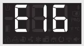
| El 6 | The configuration has been changed from 1 to 2 evaporators or vice versa. | If the configuration change is correct, start a manual calibration. |
| 0.00E+00 | Excessive door openings have been detected and the device cannot regulate in ADAPTIVE mode. | Check that the door has not been left open or that it does not open more than necessary. |
Technical specifications
| Features | Specifications | ||
| Power supply | 100 – 240 V- 50/60 Hz | ||
| Maximum input power in the operation | 6.3 VA | ||
| Maximum nominal current | 15 A | ||
| Relay SSV / DEFROST – SPDT – 20 A | NO | EN60730-1: 15 (15) A 250 V- | |
| NC | EN60730-1: 15 (13) A 250 V- | ||
| Relay FAN – SPST – 16 A | EN60730-1: 12 (9) A 250 V- | ||
| Relay COOL – SPST – 16 A | EN60730-1: 12 (9) A 250 V- | ||
| Relay AUX 1 – SPDT – 20 A | NO | EN60730-1: 15 (15) A 250 V- | |
| NC | EN60730-1: 15 (13) A 250 V- | ||
| – – Relay AUX 2 SPDT 16 A | NO | EN60730-1: 12 (9) A 250 V- | |
| NC | EN60730-1: 10 (8) A 250 V- | ||
| No. of relay operations | EN60730-1:100.000 operations | ||
| Probe temperature range | -50.0 – +99.9 °C | ||
| The resolution, setting, and differential | 0.1 °C | ||
| Thermometric precision | ±1 °C | ||
| Loading tolerance of the NTC probe at 25 °C | ±0.4 °C | ||
| Working ambient temperature | -10 – +50 °C | ||
| Storage ambient temperature | -30 – +60 °C | ||
| Protection degree | IP 65 | ||
| Installation category | II s/ EN 60730-1 | ||
| Pollution degree | II s/ EN 60730-1 | ||
| Control device classification | Built-in assembly, with Type 1. B automatic operation action feature, for use in clean situations, logical support (Software) class A and continuous operation. Degree of contamination 2 acc. to UNE-EN 60730-1. Double isolation between the power supply, secondary circuit, and relay output. | ||
| The temperature during the ball-pressure test | Accessible parts: 75 °C Parts which position active elements: 125 °C | ||
| The current of radio jamming suppression tests | 270 mA | ||
| Voltage and current as per EMC tests | 207 V, 17 mA | ||
| Type of Assembly | Fixed internal | ||
| MODBUS address | Shown on label | ||
| Dimensions | 290 mm (W) x 141 mm (H) x 84.4 mm (D) | ||
| Internal buzzer | Yes | ||
Ordering
Controller
| Model | Description | Comments | Code no. |
| AK-RC 305W-SD | AK-RC 305W-SD Gen. 2,5 0/P, Single phase | Include: 2 x 1.5 m, NTC 10K sensor | 080Z5003 |
Accessory (for spares and replacement purposes):
| Name | Features | Qty | Code no. |
| NTC sensors | 10K, High Prec. 1.5 m | 1 | 080Z3216 |

For more details, see the full User Manual and other information, and scan the QR code.
© Danfoss
Climate Solutions
AN41504517847601-000102


