TDE Instruments DPM72 Digalox® -MPN digital panel meter Instruction Manual

1. Description
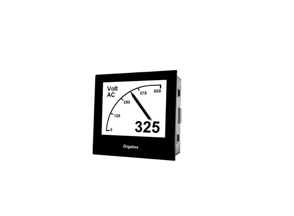
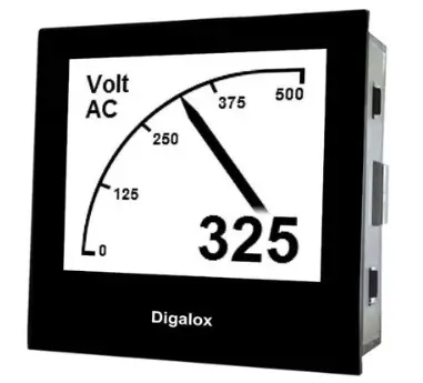
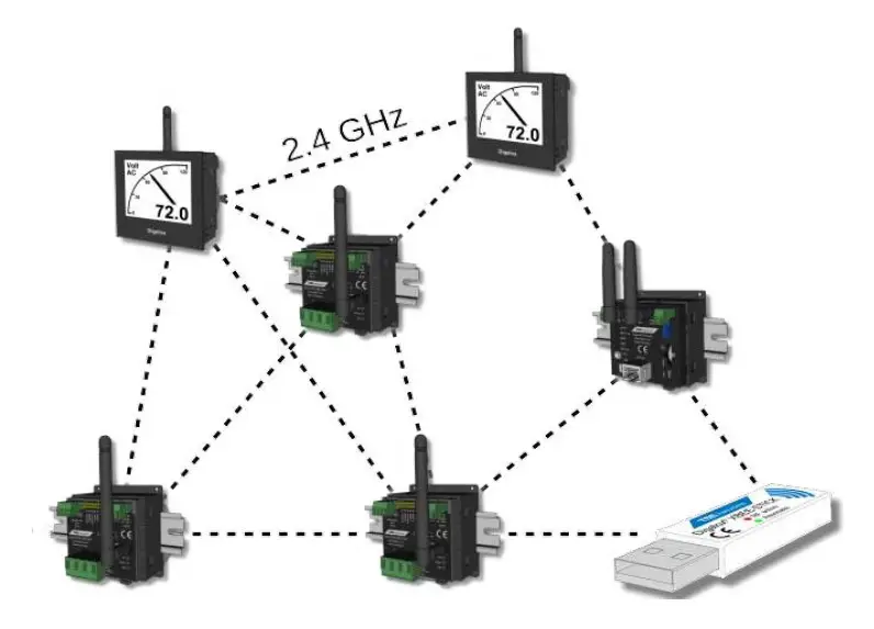
The Digalox® DPM72 devices with XBEE interface can communicate with other DPM72 devices via XBEE radio technology (2.4 GHz mesh network). In this way, measured values from remote devices can be integrated into a display as remote values. Using the radio interface the devices can also be configured individually.
The mesh network offers a robust connection that ensures continued operation even if a single radio node fails. Each additional node acts as a router, increasing the range of the network.
2. Specification
- 2.4 GHz (IEEE 802.15.4) mesh network
- Radio module: XB3-24Z8UM-J (Digi XBee 3 Zigbee 3.0, 2.4GHz, Micro, U.FL Ant, MMT)
- Antenna connector: SMA
- Range between two radio nodes: up to 60 m indoors, up to 1200 m outdoors with a clear line of sight
3. Connections
4. Configuration
To configure a device, plug the XBEE stick into the computer. The driver of the stick is installed automatically if the computer is connected to the Internet. If the XBEE connection settings of the device should be reset, short-circuit connector J8 and open it again. This switches the device to configuration mode.
The display (if present) shows “XBEE: Config”, the measurement function is deactivated.
The device can be configured using the “Digalox® Manager” software. In particular, the XBEE connection settings “Network ID” and “Link key” should be changed on the General tab so that they differ from the default settings. Afterwards, the measuring function is active. “Network ID” and “Link key” must be the same for all devices of a network.
The XBEE role “Coordinator” must be assigned to one device. The coordinator starts and manages the network. There can only be one coordinator and it must be active at all times. The other devices should receive the XBEE role “Router”. They can connect to a started network and integrate other devices.
Using the XBEE remote values tab, 4 remote values can be read from other devices. In order to display these remote values, they must be selected as value types of display values on the display values tab.
For devices with a display, all values that are to be transmitted must also be visible on the display. Devices without a display provide the first four display values. By setting jumpers J4-J6, other display values are provided accordingly.
5. Source value addresses
| Address | Data type | Description |
| 0x0000 | int8 | Chosen display value index |
| 0x0001 | int8 | (0) DC or (1) AC measurement active |
| 0x8000-0x8003 | int64 | Display value 1-4 as int64 |
| 0xC000-0xC003 | float32 | Display value 1-4 as float32 |
6. Status LEDs

There are three LEDs on the back of the device that indicate the device status.
| Description | Status |
| Power (green) shines | Device on |
| Assoc (orange) shines | Device not connected |
| Assoc (orange) flashes | Device connected |
| Act (rot) shines | Device sends data |
7. Communication status display
The state of the communication is shown on the display.

8. Messages on the display
| Display | Meaning | Solution |
| XB timeout S…x | Slave …x does not respond | Check slave configuration |
| XB tx err S…x | Data transfer problem when sending to slave …x | Check configuration |
|
XB tx err <ref> <status> | Data transfer problem reference <ref>: 255 = None 254 = Telemetry 253 = Command 252 = Slave transfer status <status>: 0x00 = Success 0x01 = No ACK received 0x22 = Not connected to network 0x35 = Encryption error 0x7A = Invalid host address … |
If necessary, read the transmit status number in the XBEE3 documen- tation |
|
XB response <slavecom_stat> S…x | Slave …x responds with error message <slavecom_stat>: 0 = OK 1 = Uninitialized 2 = Invalid command 3 = Invalid status 4 = Invalid CRC 5 = Invalid slave 6 = Invalid interface 7 = Communication failed 8 = Buffer overflow 9 = Invalid address 10 = Device failure 11 = Device busy 12 = Gateway path unavailable 13 = Gateway target device failed to respond |
Check configuration |
9. Contact details
TDE Instruments GmbH, Gewerbestraße 8, D-71144 Steinenbronn
Phone: +49 7157 20801
E-mail: [email protected]
Internet: www.tde-instruments.de, www.digalox.com


