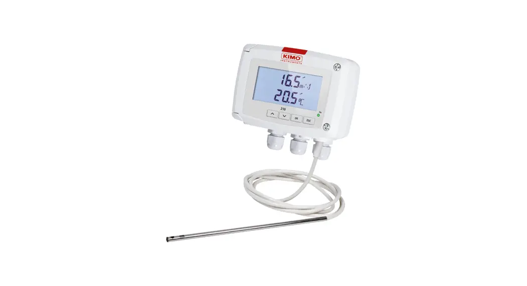
![]() CTV 210-R Air Velocity
CTV 210-R Air Velocity
Measuring Instrument
User Guide
CTV 210-R Air Velocity Measuring Instrument
Quick Start Guide
Air velocity and temperature transmitter
| Airflow function | |
 | 2 relay outputs |
 | Two 4-wire analogue output 0-5/10 V or 0/4-20 mA |
 | ABS V0 IP65 housing, optional display |
General features
Power supply
24 Vac / Vdc ±10%. 100-240 Vac, 50-60 Hz![]() Warning: risk of electric shock
Warning: risk of electric shock
| Output | 2 x 4-20 mA or 2 x 0-20 mA or 2 x 0-5 V or 2 x 0-10 V (4 wires) Common mode voltage <30 Vac. Maximum load: 500 Ohms (0/4-20 mA). Minimum load: 1 K Ohms (0-5/10 V) |
| Relay outputs | 2 changeover relays 3 A / 230 V. NO : 5A / NC: 3A / 240 Vac |
| Galvanic isolation | Inputs and outputs (models 100-240 Vac). |
| Consumption | CTV210-B: 6 VA. CTV210-H: 8 VA |
| Electrical connection | Screw terminal block for cable 2.5 mm². Carried out according to the code of good practice |
| PC communication | USB-Mini Din cable |
| Environment | Air and neutral gases |
| Conditions of use (°C/%RH/m) | From -10 to +50 °C. In non-condensing condition. From 0 to 2000 m. |
| Storage temperature | From -10 to +70 °C |
| Security | Protection class II; Pollution degree 2; Overvoltage category 2 (OVCII) |
| European directives | 2014/30/EU EMC; 2014/35/EU Low Voltage; 2011/65/EU RoHS II; 2012/19/EU WEEE |
Features of the housing
| Material | ABS V0 as per UL94 |
| Protection | IP65 |
| Display | 75 x 40 mm, LCD 20 digits 2 lines. Height of digits: Values: 10 mm; Units: 5 mm |
| Cable gland | For cables Ø 8 mm maximum |
| Weight | 340 g |
All dimensions are in millimeters.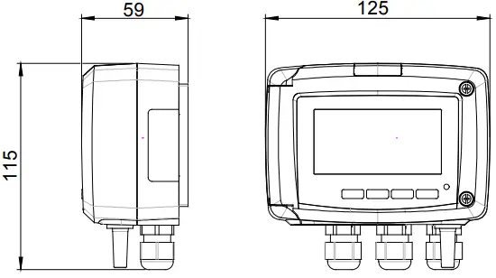 Used symbols
![]() For your safety and in order to avoid any damage of the device, please follow the procedure described in this document and read carefully the notes preceded by the following symbol:
For your safety and in order to avoid any damage of the device, please follow the procedure described in this document and read carefully the notes preceded by the following symbol:![]() Tout changement de fusible doit être réalisé appareil hors tension en utilisant un fusible TR5 630 mA 250 V.
Tout changement de fusible doit être réalisé appareil hors tension en utilisant un fusible TR5 630 mA 250 V.
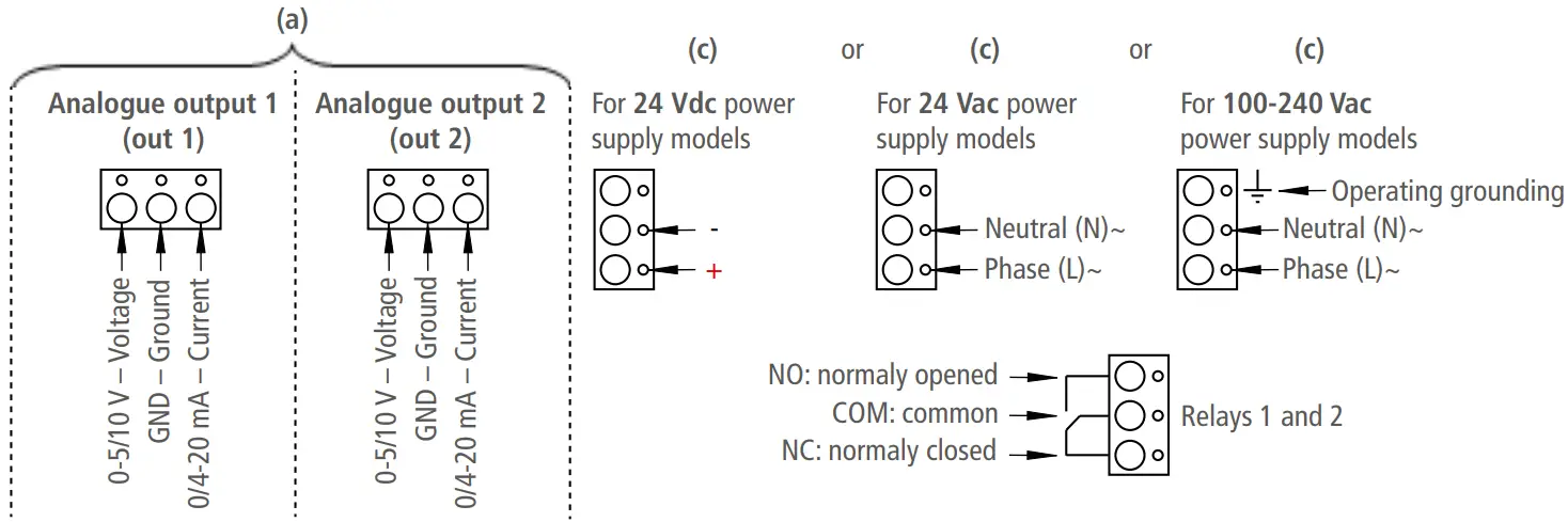
Connections
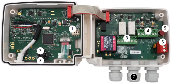
- DIP switch (d)
- LCC-S software connection
- Relays
- Analogue outputs (a)
- F3.20* fuse
- Power supply terminal block (c)
- Cable glands
Power supply type (b) specified on the label on the side of the transmitter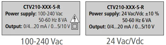
 *Fuse present only for 100-240 Vac models.
Every fuse replacement must be performed witht a power off device using a TR5 630 mA 250 V fuse.
Electrical connections as per NFC15-100 standard
![]() This connection must be made by a formed and qualified technician. To make the connection, the transmitter must not be energized. Before making the connection, you must first check the power supply indicated on the transmitter board (see (b) on “Connections” part). The presence of a switch and a circuit breaker upstream the device is compulsory.
This connection must be made by a formed and qualified technician. To make the connection, the transmitter must not be energized. Before making the connection, you must first check the power supply indicated on the transmitter board (see (b) on “Connections” part). The presence of a switch and a circuit breaker upstream the device is compulsory.
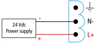
- For transmitters with 24 Vdc power supply:

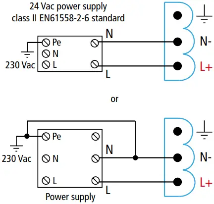
- For transmitters with 24 Vac power supply:

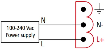
- For transmitters with 100-240 Vac power supply:

The selection of the output signal in voltage (0-10 V or 0-5 V) or in current (4-20 mA or 0-20 mA) is made via the DIP switch (d) of the electronic board of the transmitter: put the on-of switches as shown in the table below: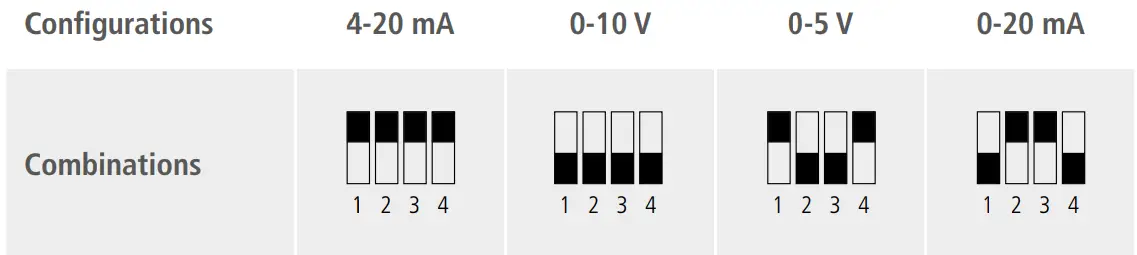
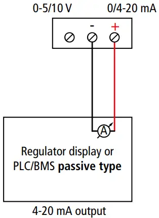
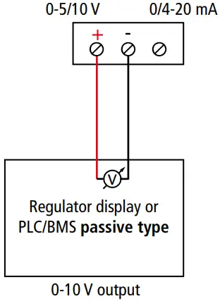
| • Connection of the output in current 4-20 mA: | • Connection of output in voltage 0-10 V: |
 |  |
![]() On 100-240 Vac models, if a fuse protection is used for the power line, it is imperative to use delayed-action fuses in order to absorb the surge of current when first turned on the transmitter.
On 100-240 Vac models, if a fuse protection is used for the power line, it is imperative to use delayed-action fuses in order to absorb the surge of current when first turned on the transmitter.
Transmitters configuration
It is possible on the class 210 to configure all the parameters managed by the transmitter : units, measuring ranges, outputs, channels, calculation functions, etc, via different methods:
- Keypad for models with display : a code-locking system allows to secure the installation (See class 210 user manual).
- Software (optional) on all models. Simple user-friendly configuration. See LCC-SD user manual.
Configurable analogue output:
Range with central zero (-50/0/+50 Pa), with offset zero (-300/0/+70 Pa) or standard range (0/+100 Pa), it is possible to configure your own intermediate ranges.
Caution: the minimum difference between the high range and the low range is 20.
Configure the range according to your needs: outputs are automatically adjusted to the new measuring range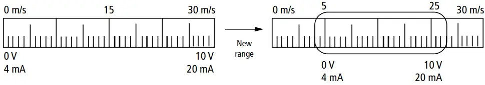 Mounting
To mount the transmitter, mount the ABS plate on the wall (drilling: Ø6 mm, screws and pins are supplied). Insert the transmitter on the fixing plate (see A on the drawing beside). Rotate the housing in clockwise direction until you hear a “click” which confirms that the transmitter is correctly installed.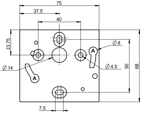 Accessories
Please refer to the data sheet to get more information about available accessories.
Maintenance: please avoid any aggressive solvents. Please protect the transmitter and its probes from any cleaning product containing formalin, that may be used for cleaning rooms or ducts.
Precautions for use: please always use the device in accordance with its intended use and within parameters described in the technical features in order not to compromise the protection ensured by the device.
Download the full manual https://sauermanngroup.com/fr-INT/technical-documents?search=ctv+210
Customer service portal Use our Customer service portal to contact us https://sauermann-en.custhelp.com
QSG – CTV 210-R – 07/10/2022 – Non-contractual document – We reserve the right to modify the characteristics of our products without prior notice


