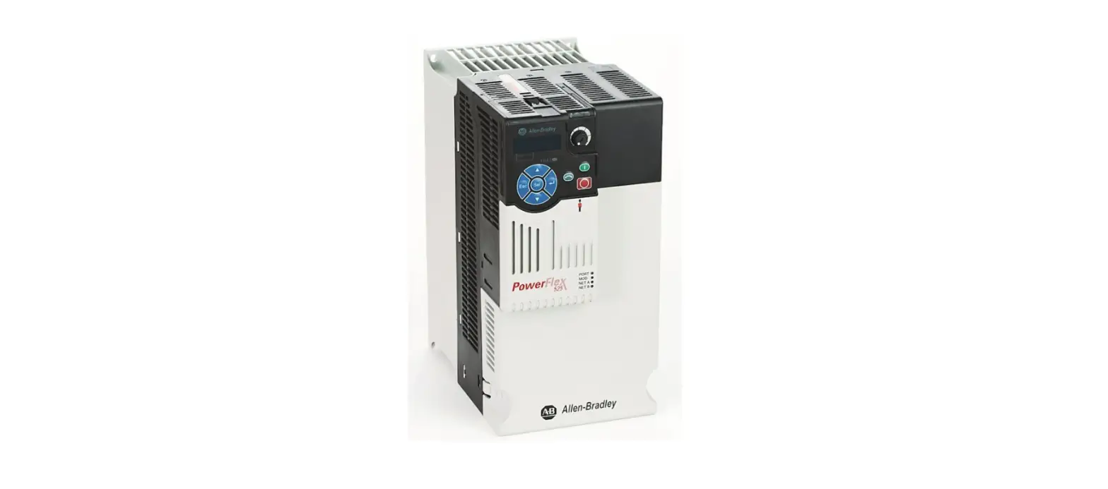
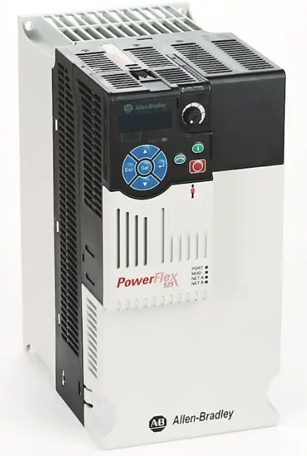
Allen-Bradley 525 PowerFlex Adjustable Frequency Guide
 Parameter Groups
 Parameter Groups
| Basic Display | b | Drive Status | b006 | Control Source | b012 | Power Saved | b018 | Accum kWh Sav | b024 |
| Output Freq | b001 | Fault 1 Code | b007 | Contrl In Status | b013 | Elapsed Run Time | b019 | Accum Cost Sav | b025 |
| Commanded Freq | b002 | Fault 2 Code | b008 | Dig In Status | b014 | Average Power | b020 | Accum CO2 Sav | b026 |
| Output Current | b003 | Fault 3 Code | b009 | Output RPM | b015 | Elapsed kWh | b021 | Drive Temp | b027 |
| Output Voltage | b004 | Process Display | b010 | Output Speed | b016 | Elapsed MWh | b022 | Control Temp | b028 |
| DC Bus Voltage | b005 | Process Fract | b011 | Output Power | b017 | Energy Saved | b023 | Control SW Ver | b029 |
| Basic Program | P | Motor NP FLA | P034 | Torque Perf Mode | P039 | Maximum Freq | P044 | Speed Reference2 | P049 |
| Language | P030 | Motor NP Poles | P035 | Autotune | P040 | Stop Mode | P045 | Start Source 3 | P050 |
| Motor NP Volts | P031 | Motor NP RPM | P036 | Accel Time 1 | P041 | Start Source 1 | P046 | Speed Reference3 | P051 |
| Motor NP Hertz | P032 | Motor NP Power | P037 | Decel Time 1 | P042 | Speed Reference1 | P047 | Average kWh Cost | P052 |
| Motor OL Current | P033 | Voltage Class | P038 | Minimum Freq | P043 | Start Source 2 | P048 | Reset To Defalts | P053 |
| Terminal Blocks | t | Opto Out1 LevelF | t071 | Relay Out2 Sel | t081 | Anlg In 0-10V Lo | t091 | Sleep Level | t101 |
| DigIn TermBlk 02 | t062 | Opto Out2 Sel | t072 | Relay Out2 Level | t082 | Anlg In 0-10V Hi | t092 | Sleep Time | t102 |
| DigIn TermBlk 03 | t063 | Opto Out2 Level | t073 | Relay Out2 LevelF | t083 | 10V Bipolar Enbl | t093 | Wake Level | t103 |
| 2-Wire Mode | t064 | Opto Out2 LevelF | t074 | Relay 2 On Time | t084 | Anlg In V Loss | t094 | Wake Time | t104 |
| DigIn TermBlk 05 | t065 | Opto Out Logic | t075 | Relay 2 Off Time | t085 | Anlg In4-20mA Lo | t095 | Safety Open En | t105 |
| DigIn TermBlk 06 | t066 | Relay Out1 Sel | t076 | EM Brk Off Delay | t086 | Anlg In4-20mA Hi | t096 | SafetyFlt RstCfg(1) | t106 |
| DigIn TermBlk 07 | t067 | Relay Out1 Level | t077 | EM Brk On Delay | t087 | Anlg In mA Loss | t097 | ||
| DigIn TermBlk 08 | t068 | Relay Out1 LevelF | t078 | Analog Out Sel | t088 | Anlg Loss Delay | t098 | ||
| Opto Out1 Sel | t069 | Relay 1 On Time | t079 | Analog Out High | t089 | Analog In Filter | t099 | ||
| Opto Out1 Level | t070 | Relay 1 Off Time | t080 | Anlg Out Setpt | t090 | Sleep-Wake Sel | t100 | ||
| Communications | C | EN IP Addr Cfg 3 | C131 | EN Comm Flt Actn | C143 | EN Data In 4 | C156 | Opt Data Out 3 | C167 |
| Comm Write Mode | C121 | EN IP Addr Cfg 4 | C132 | EN Idle Flt Actn | C144 | EN Data Out 1 | C157 | Opt Data Out 4 | C168 |
| Cmd Stat Select | C122 | EN Subnet Cfg 1 | C133 | EN Flt Cfg Logic | C145 | EN Data Out 2 | C158 | MultiDrv Sel | C169 |
| RS485 Data Rate | C123 | EN Subnet Cfg 2 | C134 | EN Flt Cfg Ref | C146 | EN Data Out 3 | C159 | Drv 1 Addr | C171 |
| RS485 Node Addr | C124 | EN Subnet Cfg 3 | C135 | EN Flt Cfg DL 1 | C147 | EN Data Out 4 | C160 | Drv 2 Addr | C172 |
| Comm Loss Action | C125 | EN Subnet Cfg 4 | C136 | EN Flt Cfg DL 2 | C148 | Opt Data In 1 | C161 | Drv 3 Addr | C173 |
| Comm Loss Time | C126 | EN Gateway Cfg 1 | C137 | EN Flt Cfg DL 3 | C149 | Opt Data In 2 | C162 | Drv 4 Addr | C174 |
| RS485 Format | C127 | EN Gateway Cfg 2 | C138 | EN Flt Cfg DL 4 | C150 | Opt Data In 3 | C163 | DSI I/O Cfg | C175 |
| EN Addr Sel | C128 | EN Gateway Cfg 3 | C139 | EN Data In 1 | C153 | Opt Data In 4 | C164 | ||
| EN IP Addr Cfg 1 | C129 | EN Gateway Cfg 4 | C140 | EN Data In 2 | C154 | Opt Data Out 1 | C165 | ||
| EN IP Addr Cfg 2 | C130 | EN Rate Cfg | C141 | EN Data In 3 | C155 | Opt Data Out 2 | C166 | ||
| Logic | L | Stp Logic 6 | L186 | Stp Logic Time 5 | L195 | Step Units 2 | L204 | Step Units F 5 | L211 |
| Stp Logic 0 | L180 | Stp Logic 7 | L187 | Stp Logic Time 6 | L196 | Step Units F 2 | L205 | Step Units 6 | L212 |
| Stp Logic 1 | L181 | Stp Logic Time 0 | L190 | Stp Logic Time 7 | L197 | Step Units 3 | L206 | Step Units F 6 | L213 |
| Stp Logic 2 | L182 | Stp Logic Time 1 | L191 | Step Units 0 | L200 | Step Units F 3 | L207 | Step Units 7 | L214 |
| Stp Logic 3 | L183 | Stp Logic Time 2 | L192 | Step Units F 0 | L201 | Step Units 4 | L208 | Step Units F 7 | L215 |
| Stp Logic 4 | L184 | Stp Logic Time 3 | L193 | Step Units 1 | L202 | Step Units F 4 | L209 | ||
| Stp Logic 5 | L185 | Stp Logic Time 4 | L194 | Step Units F 1 | L203 | Step Units 5 | L210 | ||
| Advanced Display | d | Timer StatusF | d366 | Encoder Speed | d378 | PID2 Fdbk Displ | d385 | RdyBit Mode Act | d392 |
| Analog In 0-10V | d360 | Drive Type | d367 | Encoder Speed F | d379 | PID2 Setpnt Disp | d386 | Drive Status 2(1) | d393 |
| Analog In 4-20mA | d361 | Testpoint Data | d368 | DC Bus Ripple | d380 | Position Status | d387 | Dig Out Status(1) | d394 |
| Elapsed Time-hr | d362 | Motor OL Level | d369 | Output Powr Fctr | d381 | Units Traveled H | d388 | ||
| Elapsed Time-min | d363 | Slip Hz Meter | d375 | Torque Current | d382 | Units Traveled L | d389 | ||
| Counter Status | d364 | Speed Feedback | d376 | PID1 Fdbk Displ | d383 | Fiber Status | d390 | ||
| Timer Status | d365 | Speed Feedback F | d377 | PID1 Setpnt Disp | d384 | Stp Logic Status | d391 |
Additional parameters are listed on the previous page
| Advanced Program | A | Accel Time 3 | A444 | PID 2 Invert Err | A479 | PM HIFI NS Cur(1) | A519 | Drv Ambient Sel | A554 |
| Preset Freq 0 | A410 | Decel Time 3 | A445 | Process Disp Lo | A481 | PM Bus Reg Kd(1) | A520 | Reset Meters | A555 |
| Preset Freq 1 | A411 | Accel Time 4 | A446 | Process Disp Hi | A482 | Freq 1 Kp | A521 | Text Scroll | A556 |
| Preset Freq 2 | A412 | Decel Time 4 | A447 | Testpoint Sel | A483 | Freq 1 Ki | A522 | Out Phas Loss En | A557 |
| Preset Freq 3 | A413 | Skip Frequency 1 | A448 | Current Limit 1 | A484 | Freq 2 Kp | A523 | Positioning Mode | A558 |
| Preset Freq 4 | A414 | Skip Freq Band 1 | A449 | Current Limit 2 | A485 | Freq 2 Ki | A524 | Counts Per Unit | A559 |
| Preset Freq 5 | A415 | Skip Frequency 2 | A450 | Shear Pin1 Level | A486 | Freq 3 Kp | A525 | Enh Control Word | A560 |
| Preset Freq 6 | A416 | Skip Freq Band 2 | A451 | Shear Pin 1 Time | A487 | Freq 3 Ki | A526 | Home Save | A561 |
| Preset Freq 7 | A417 | Skip Frequency 3 | A452 | Shear Pin2 Level | A488 | PM FWKn 1 Kp(1) | A527 | Find Home Freq | A562 |
| Preset Freq 8 | A418 | Skip Freq Band 3 | A453 | Shear Pin 2 Time | A489 | PM FWKn 2 Kp(1) | A528 | Find Home Dir | A563 |
| Preset Freq 9 | A419 | Skip Frequency 4 | A454 | Load Loss Level | A490 | PM Control Cfg(1) | A529 | Encoder Pos Tol | A564 |
| Preset Freq 10 | A420 | Skip Freq Band 4 | A455 | Load Loss Time | A491 | Boost Select | A530 | Pos Reg Filter | A565 |
| Preset Freq 11 | A421 | PID 1 Trim Hi | A456 | Stall Fault Time | A492 | Start Boost | A531 | Pos Reg Gain | A566 |
| Preset Freq 12 | A422 | PID 1 Trim Lo | A457 | Motor OL Select | A493 | Break Voltage | A532 | Max Traverse | A567 |
| Preset Freq 13 | A423 | PID 1 Trim Sel | A458 | Motor OL Ret | A494 | Break Frequency | A533 | Traverse Inc | A568 |
| Preset Freq 14 | A424 | PID 1 Ref Sel | A459 | Drive OL Mode | A495 | Maximum Voltage | A534 | Traverse Dec | A569 |
| Preset Freq 15 | A425 | PID 1 Fdback Sel | A460 | IR Voltage Drop | A496 | Motor Fdbk Type | A535 | P Jump | A570 |
| Keypad Freq | A426 | PID 1 Prop Gain | A461 | Flux Current Ref | A497 | Encoder PPR | A536 | Sync Time | A571 |
| MOP Freq | A427 | PID 1 Integ Time | A462 | Motor Rr | A498 | Pulse In Scale | A537 | Speed Ratio | A572 |
| MOP Reset Sel | A428 | PID 1 Diff Rate | A463 | Motor Lm | A499 | Ki Speed Loop | A538 | Mtr Options Cfg | A573 |
| MOP Preload | A429 | PID 1 Setpoint | A464 | Motor Lx | A500 | Kp Speed Loop | A539 | RdyBit Mode Cfg | A574 |
| MOP Time | A430 | PID 1 Deadband | A465 | PM IR Voltage(1) | A501 | Var PWM Disable | A540 | Flux Braking En(1) | A575 |
| Jog Frequency | A431 | PID 1 Preload | A466 | PM IXd Voltage(1) | A502 | Auto Rstrt Tries | A541 | Phase Loss Level(1) | A576 |
| Jog Accel/Decel | A432 | PID 1 Invert Err | A467 | PM IXq Voltage(1) | A503 | Auto Rstrt Delay | A542 | Current Loop BW(1) | A580 |
| Purge Frequency | A433 | PID 2 Trim Hi | A468 | PM BEMF Voltage(1) | A504 | Start At PowerUp | A543 | PM Stable 1 Freq(1) | A581 |
| DC Brake Time | A434 | PID 2 Trim Lo | A469 | Speed Reg Sel | A509 | Reverse Disable | A544 | PM Stable 2 Freq(1) | A582 |
| DC Brake Level | A435 | PID 2 Trim Sel | A470 | Freq 1 | A510 | Flying Start En | A545 | PM Stable 1 Kp(1) | A583 |
| DC Brk Time@Strt | A436 | PID 2 Ref Sel | A471 | Freq 1 BW | A511 | FlyStrt CurLimit | A546 | PM Stable 2 Kp(1) | A584 |
| DB Resistor Sel | A437 | PID 2 Fdback Sel | A472 | Freq 2 | A512 | Compensation | A547 | PM Stable Brk Pt(1) | A585 |
| DB Threshold | A438 | PID 2 Prop Gain | A473 | Freq 2 BW | A513 | Power Loss Mode | A548 | PM Stepload Kp(1) | A586 |
| S Curve % | A439 | PID 2 Integ Time | A474 | Freq 3 | A514 | Half Bus Enable | A549 | PM 1 Efficiency(1) | A587 |
| PWM Frequency | A440 | PID 2 Diff Rate | A475 | Freq 3 BW | A515 | Bus Reg Enable | A550 | PM 2 Efficiency(1) | A588 |
| Droop Hertz@ FLA | A441 | PID 2 Setpoint | A476 | PM Initial Sel(1) | A516 | Fault Clear | A551 | PM Algor Sel(1) | A589 |
| Accel Time 2 | A442 | PID 2 Deadband | A477 | PM DC Inject Cur(1) | A517 | Program Lock | A552 | ||
| Decel Time 2 | A443 | PID 2 Preload | A478 | PM Align Time(1) | A518 | Program Lock Mod | A553 | ||
| Network | N | This group contains parameters for the network option card that is installed. | |||||||
| Modified | M | This group contains parameters that have their values changed from the factory default. | |||||||
| Fault and Diagnostic | F | Fault 7 Time-min | F627 | Fault 1 BusVolts | F651 | EN Rate Act | F685 | Drv 1 Logic Cmd | F709 |
| Fault 4 Code | F604 | Fault 8 Time-min | F628 | Fault 2 BusVolts | F652 | DSI I/O Act | F686 | Drv 1 Reference | F710 |
| Fault 5 Code | F605 | Fault 9 Time-min | F629 | Fault 3 BusVolts | F653 | HW Addr 1 | F687 | Drv 1 Logic Sts | F711 |
| Fault 6 Code | F606 | Fault10 Time-min | F630 | Fault 4 BusVolts | F654 | HW Addr 2 | F688 | Drv 1 Feedback | F712 |
| Fault 7 Code | F607 | Fault 1 Freq | F631 | Fault 5 BusVolts | F655 | HW Addr 3 | F689 | Drv 2 Logic Cmd | F713 |
| Fault 8 Code | F608 | Fault 2 Freq | F632 | Fault 6 BusVolts | F656 | HW Addr 4 | F690 | Drv 2 Reference | F714 |
| Fault 9 Code | F609 | Fault 3 Freq | F633 | Fault 7 BusVolts | F657 | HW Addr 5 | F691 | Drv 2 Logic Sts | F715 |
| Fault10 Code | F610 | Fault 4 Freq | F634 | Fault 8 BusVolts | F658 | HW Addr 6 | F692 | Drv 2 Feedback | F716 |
| Fault 1 Time-hr | F611 | Fault 5 Freq | F635 | Fault 9 BusVolts | F659 | EN IP Addr Act 1 | F693 | Drv 3 Logic Cmd | F717 |
| Fault 2 Time-hr | F612 | Fault 6 Freq | F636 | Fault10 BusVolts | F660 | EN IP Addr Act 2 | F694 | Drv 3 Reference | F718 |
| Fault 3 Time-hr | F613 | Fault 7 Freq | F637 | Status @ Fault 1 | F661 | EN IP Addr Act 3 | F695 | Drv 3 Logic Sts | F719 |
| Fault 4 Time-hr | F614 | Fault 8 Freq | F638 | Status @ Fault 2 | F662 | EN IP Addr Act 4 | F696 | Drv 3 Feedback | F720 |
| Fault 5 Time-hr | F615 | Fault 9 Freq | F639 | Status @ Fault 3 | F663 | EN Subnet Act 1 | F697 | Drv 4 Logic Cmd | F721 |
| Fault 6 Time-hr | F616 | Fault10 Freq | F640 | Status @ Fault 4 | F664 | EN Subnet Act 2 | F698 | Drv 4 Reference | F722 |
| Fault 7 Time-hr | F617 | Fault 1 Current | F641 | Status @ Fault 5 | F665 | EN Subnet Act 3 | F699 | Drv 4 Logic Sts | F723 |
| Fault 8 Time-hr | F618 | Fault 2 Current | F642 | Status @ Fault 6 | F666 | EN Subnet Act 4 | F700 | Drv 4 Feedback | F724 |
| Fault 9 Time-hr | F619 | Fault 3 Current | F643 | Status @ Fault 7 | F667 | EN Gateway Act 1 | F701 | EN Rx Overruns | F725 |
| Fault10 Time-hr | F620 | Fault 4 Current | F644 | Status @ Fault 8 | F668 | EN Gateway Act 2 | F702 | EN Rx Packets | F726 |
| Fault 1 Time-min | F621 | Fault 5 Current | F645 | Status @ Fault 9 | F669 | EN Gateway Act 3 | F703 | EN Rx Errors | F727 |
| Fault 2 Time-min | F622 | Fault 6 Current | F646 | Status @ Fault10 | F670 | EN Gateway Act 4 | F704 | EN Tx Packets | F728 |
| Fault 3 Time-min | F623 | Fault 7 Current | F647 | Comm Sts – DSI | F681 | Drv 0 Logic Cmd | F705 | EN Tx Errors | F729 |
| Fault 4 Time-min | F624 | Fault 8 Current | F648 | Comm Sts – Opt | F682 | Drv 0 Reference | F706 | EN Missed IO Pkt | F730 |
| Fault 5 Time-min | F625 | Fault 9 Current | F649 | Com Sts-Emb Enet | F683 | Drv 0 Logic Sts | F707 | DSI Errors | F731 |
| Fault 6 Time-min | F626 | Fault10 Current | F650 | EN Addr Src | F684 | Drv 0 Feedback | F708 |
The parameter is available in FRN 5. xxx and later
AppView Parameter Groups
| Conveyor | G1 | Motor NP FLA | P034 | Stop Mode | P045 | Anlg In 0-10V Hi | t092 | Jog Accel/Decel | A432 |
| Language | P030 | Motor NP Poles | P035 | Start Source 1 | P046 | Anlg In4-20mA Lo | t095 | S Curve % | A439 |
| Output Freq | b001 | Autotune | P040 | Speed Reference1 | P047 | Anlg In4-20mA Hi | t096 | Reverse Disable | A544 |
| Commanded Freq | b002 | Accel Time 1 | P041 | DigIn TermBlk 02 | t062 | Anlg In mA Loss | t097 | ||
| Motor NP Volts | P031 | Decel Time 1 | P042 | DigIn TermBlk 03 | t063 | Slip Hz Meter | d375 | ||
| Motor NP Hertz | P032 | Minimum Freq | P043 | Relay Out1 Sel | t076 | Preset Freq 0 | A410 | ||
| Motor OL Current | P033 | Maximum Freq | P044 | Anlg In 0-10V Lo | t091 | Jog Frequency | A431 | ||
| Mixer | G2 | Motor NP Hertz | P032 | Decel Time 1 | P042 | Relay Out1 Sel | t076 | Preset Freq 0 | A410 |
| Language | P030 | Motor OL Current | P033 | Minimum Freq | P043 | Anlg In 0-10V Lo | t091 | Stall Fault Time | A492 |
| Output Freq | b001 | Motor NP FLA | P034 | Maximum Freq | P044 | Anlg In 0-10V Hi | t092 | ||
| Commanded Freq | b002 | Motor NP Poles | P035 | Stop Mode | P045 | Anlg In4-20mA Lo | t095 | ||
| Output Current | b003 | Autotune | P040 | Start Source 1 | P046 | Anlg In4-20mA Hi | t096 | ||
| Motor NP Volts | P031 | Accel Time 1 | P041 | Speed Reference1 | P047 | Anlg In mA Loss | t097 | ||
| Compressor | G3 | Motor OL Current | P033 | Minimum Freq | P043 | Anlg In 0-10V Lo | t091 | Auto Rstrt Tries | A541 |
| Language | P030 | Motor NP FLA | P034 | Maximum Freq | P044 | Anlg In 0-10V Hi | t092 | Auto Rstrt Delay | A542 |
| Output Freq | b001 | Motor NP Poles | P035 | Stop Mode | P045 | Anlg In4-20mA Lo | t095 | Start At PowerUp | A543 |
| Commanded Freq | b002 | Autotune | P040 | Start Source 1 | P046 | Anlg In4-20mA Hi | t096 | Reverse Disable | A544 |
| Motor NP Volts | P031 | Accel Time 1 | P041 | Speed Reference1 | P047 | Anlg In mA Loss | t097 | Power Loss Mode | A548 |
| Motor NP Hertz | P032 | Decel Time 1 | P042 | Relay Out1 Sel | t076 | Preset Freq 0 | A410 | Half Bus Enable | A549 |
| Centrifugal Pump | G4 | Motor NP Poles | P035 | Speed Reference1 | P047 | PID 1 Trim Hi | A456 | PID 1 Deadband | A465 |
| Language | P030 | Autotune | P040 | Relay Out1 Sel | t076 | PID 1 Trim Lo | A457 | PID 1 Preload | A466 |
| Output Freq | b001 | Accel Time 1 | P041 | Anlg In 0-10V Lo | t091 | PID 1 Ref Sel | A459 | Auto Rstrt Tries | A541 |
| Commanded Freq | b002 | Decel Time 1 | P042 | Anlg In 0-10V Hi | t092 | PID 1 Fdback Sel | A460 | Auto Rstrt Delay | A542 |
| Motor NP Volts | P031 | Minimum Freq | P043 | Anlg In4-20mA Lo | t095 | PID 1 Prop Gain | A461 | Start At PowerUp | A543 |
| Motor NP Hertz | P032 | Maximum Freq | P044 | Anlg In4-20mA Hi | t096 | PID 1 Integ Time | A462 | Reverse Disable | A544 |
| Motor OL Current | P033 | Stop Mode | P045 | Anlg In mA Loss | t097 | PID 1 Diff Rate | A463 | ||
| Motor NP FLA | P034 | Start Source 1 | P046 | Preset Freq 0 | A410 | PID 1 Setpoint | A464 |
| Blower/Fan | G5 | Motor NP Poles | P035 | Speed Reference1 | P047 | PID 1 Trim Hi | A456 | PID 1 Deadband | A465 |
| Language | P030 | Autotune | P040 | Relay Out1 Sel | t076 | PID 1 Trim Lo | A457 | PID 1 Preload | A466 |
| Output Freq | b001 | Accel Time 1 | P041 | Anlg In 0-10V Lo | t091 | PID 1 Ref Sel | A459 | Auto Rstrt Tries | A541 |
| Commanded Freq | b002 | Decel Time 1 | P042 | Anlg In 0-10V Hi | t092 | PID 1 Fdback Sel | A460 | Auto Rstrt Delay | A542 |
| Motor NP Volts | P031 | Minimum Freq | P043 | Anlg In4-20mA Lo | t095 | PID 1 Prop Gain | A461 | Start At PowerUp | A543 |
| Motor NP Hertz | P032 | Maximum Freq | P044 | Anlg In4-20mA Hi | t096 | PID 1 Integ Time | A462 | Reverse Disable | A544 |
| Motor OL Current | P033 | Stop Mode | P045 | Anlg In mA Loss | t097 | PID 1 Diff Rate | A463 | Flying Start En | A545 |
| Motor NP FLA | P034 | Start Source 1 | P046 | Preset Freq 0 | A410 | PID 1 Setpoint | A464 | ||
| Extruder | G6 | Motor OL Current | P033 | Maximum Freq | P044 | Anlg In4-20mA Lo | t095 | Pulse In Scale | A537 |
| Language | P030 | Motor NP FLA | P034 | Stop Mode | P045 | Anlg In4-20mA Hi | t096 | Power Loss Mode | A548 |
| Output Freq | b001 | Motor NP Poles | P035 | Start Source 1 | P046 | Anlg In mA Loss | t097 | Half Bus Enable | A549 |
| Commanded Freq | b002 | Autotune | P040 | Speed Reference1 | P047 | Slip Hz Meter | d375 | ||
| Output Current | b003 | Accel Time 1 | P041 | Relay Out1 Sel | t076 | Speed Feedback | d376 | ||
| Motor NP Volts | P031 | Decel Time 1 | P042 | Anlg In 0-10V Lo | t091 | Preset Freq 0 | A410 | ||
| Motor NP Hertz | P032 | Minimum Freq | P043 | Anlg In 0-10V Hi | t092 | Stall Fault Time | A492 | ||
| Textile/Fiber | G8 | Autotune | P040 | DigIn TermBlk 03 | t063 | Preset Freq 0 | A410 | Traverse Inc | A568 |
| Language | P030 | Accel Time 1 | P041 | Relay Out1 Sel | t076 | Jog Frequency | A431 | Traverse Dec | A569 |
| Output Freq | b001 | Decel Time 1 | P042 | Anlg In 0-10V Lo | t091 | Jog Accel/Decel | A432 | P Jump | A570 |
| Commanded Freq | b002 | Minimum Freq | P043 | Anlg In 0-10V Hi | t092 | S Curve % | A439 | Sync Time | A571 |
| Motor NP Volts | P031 | Maximum Freq | P044 | Anlg In4-20mA Lo | t095 | Reverse Disable | A544 | Speed Ratio | A572 |
| Motor NP Hertz | P032 | Stop Mode | P045 | Anlg In4-20mA Hi | t096 | Power Loss Mode | A548 | ||
| Motor OL Current | P033 | Start Source 1 | P046 | Anlg In mA Loss | t097 | Half Bus Enable | A549 | ||
| Motor NP FLA | P034 | Speed Reference1 | P047 | Slip Hz Meter | d375 | Bus Reg Enable | A550 | ||
| Motor NP Poles | P035 | DigIn TermBlk 02 | t062 | Fiber Status | d390 | Max Traverse | A567 |
CustomView Parameter Group
Custom GC This group can store up to 100 of your frequently used parameters for your application
Fault Descriptions
| No. | Fault | Type(1) | Description | Action |
| F000 | No Fault | – | No fault present. | – |
| F002 | Auxiliary Input | 1 | External trip (Auxiliary) input. | • Check remote wiring. • Verify communications programming for intentional fault. |
| F003 | Power Loss | 2 | Single phase operation detected with excessive load. | • Monitor the incoming AC line for low voltage or line power interruption. • Check input fuses. • Reduce load. |
| F004 | UnderVoltage | 1 | DC bus voltage fell below the minimum value. | Monitor the incoming AC line for low voltage or line power interruption. |
| F005 | OverVoltage | 1 | DC bus voltage exceeded maximum value. | Monitor the AC line for high line voltage or transient conditions. Bus overvoltage can also be caused by motor regeneration. Extend the decel time or install dynamic brake option. |
| F006 | Motor Stalled | 1 | Drive is unable to accelerate or decelerate motor. | • Increase P041, A442, A444, A446 [Accel Time x] or reduce load so drive output current does not exceed the current set by parameter A484, A485 [Current Limit x] for too long. • Check for overhauling load. |
| F007 | Motor Overload | 1 | Internal electronic overload trip. | • An excessive motor load exists. Reduce load so drive output current does not exceed the current set by parameter P033 [Motor OL Current]. • Verify A530 [Boost Select] setting. |
| F008 | Heatsink OvrTmp | 1 | Heatsink/Power Module temperature exceeds a predefined value. | • Check for blocked or dirty heat sink fins. Verify that ambient temperature has not exceeded the rated ambient temperature. • Check fan. |
| F009 | CC OvrTmp | 1 | Control module temperature exceeds a predefined value. | • Check product ambient temperature. • Check for airflow obstruction. • Check for dirt or debris. • Check fan. |
| F012 | HW OverCurrent | 2 | The drive output current has exceeded the hardware current limit. | Check programming. Check for excess load, improper A530 [Boost Select] setting, DC brake volts set too high or other causes of excess current. |
| F013 | Ground Fault | 1(2) | A current path to earth ground has been detected at one or more of the drive output terminals. | Check the motor and external wiring to the drive output terminals for a grounded condition. |
| F015 | Load Loss | 2 | The output torque current is below the value programmed in A490 [Load Loss Level] for a time period greater than the time programmed in A491 [Load Loss Time]. | • Verify connections between motor and load. • Verify level and time requirements |
| F021 | Output Ph Loss | 1 | Output Phase Loss (if enabled). Configure with A557 [Output Phas Loss En]. | • Verify motor wiring. • Verify motor. |
| F029 | Analog In Loss | 1 | An analog input is configured to fault on signal loss. A signal loss has occurred. Configure with t094 [Anlg In V Loss] or t097 [Anlg In mA Loss]. | • Check for broken/loose connections at inputs. • Check parameters. |
| F033 | Auto Rstrt Tries | 2 | Drive unsuccessfully attempted to reset a fault and resume running for the programmed number of A541 [Auto Rstrt Tries]. | Correct the cause of the fault and manually clear. |
| F038 | Phase U to Gnd | 2 | A phase to ground fault has been detected between the drive and motor in this phase. | • Check the wiring between the drive and motor. • Check motor for grounded phase. • Replace drive if fault cannot be cleared. |
| F039 | Phase V to Gnd | |||
| F040 | Phase W to Gnd | |||
| F041 | Phase UV Short | 2 | Excessive current has been detected between these two output terminals. | Check the motor and drive output terminal wiring for a shorted condition. Replace drive if fault cannot be cleared. |
| F042 | Phase UW Short | |||
| F043 | Phase VW Short | |||
| F048 | Params Defaulted | 1 | The drive was commanded to write default values to EEPROM. | • Clear the fault or cycle power to the drive. • Program the drive parameters as needed. |
| F059 | Safety Open | 1 | Both of the safety inputs (Safety 1, Safety 2) are not enabled. Configure with t105 [Safety Open En]. | Check safety input signals. If not using safety, verify and tighten jumper for I/O terminals S1, S2 and S+. |
| F063 | SW OverCurrent | 1 | Programmed A486, A488 [Shear Pinx Level] has been exceeded for a time period greater than the time programmed in A487, A489 [Shear Pin x Time]. | • Verify connections between motor and load. • Verify level and time requirements. |
| F064 | Drive Overload | 2 | Drive overload rating has been exceeded. | Reduce load or extend Accel Time. |
| F070 | Power Unit | 2 | Failure has been detected in the drive power section. | • Check maximum ambient temperature has not been exceeded. • Cycle power. • Replace drive if fault cannot be cleared. |
| F071 | DSI Net Loss | 2 | Control over the Modbus or DSI communications link has been interrupted. | • Cycle power. • Check communications cabling. • Check Modbus or DSI setting. • Check Modbus or DSI status. |
| F072 | Opt Net Loss | 2 | Control over the network option card’s remote network has been interrupted. | • Cycle power. • Check communications cabling. • Check network adapter setting. • Check external network status. |
| F073 | EN Net Loss | 2 | Control through the embedded EtherNet/IP adapter has been interrupted. | • Cycle power. • Check communications cabling. • Check EtherNet/IP setting. • Check external network status. |
| F080 | Autotune Failure | 2 | The autotune function was either cancelled by the user or failed. | Restart procedure. |
|
F081 |
DSI Comm Loss |
2 |
Communications between the drive and the Modbus or DSI master device have been interrupted. | • Cycle power. • Check communications cabling. • Check Modbus or DSI setting. • Check Modbus or DSI status. • Modify using C125 [Comm Loss Action]. • Connecting I/O terminals C1 and C2 to ground may improve noise immunity. • Replace wiring, Modbus master device, or control module. |
| F082 | Opt Comm Loss | 2 | Communications between the drive and the network option card have been interrupted. | • Cycle power. • Reinstall option card in drive. • Modify using C125 [Comm Loss Action]. • Replace wiring, port expander, option card, or control module. |
| F083 | EN Comm Loss | 2 | Internal communications between the drive and the embedded EtherNet/IP adapter have been interrupted. | • Cycle power. • Check EtherNet/IP setting. • Check drive’s Ethernet settings and diagnostic parameters. • Modify using C125 [Comm Loss Action]. • Replace wiring, Ethernet switch, or control module. |
| F091 | Encoder Loss | 2 | Requires differential encoder. One of the 2 encoder channel signals is missing. | • Check Wiring. • If P047, P049, P051 [Speed Referencex] = 16 “Positioning” and A535 [Motor Fdbk Type] = 5 “Quad Check”, swap the Encoder channel inputs or swap any two motor leads. • Replace encoder. |
| F094 | Function Loss | 2 | “Freeze-Fire” (Function Loss) input is inactive, input to the programmed terminal is open. | Close input to the terminal and cycle power. |
| F100 | Parameter Chksum | 2 | Drive parameter non-volatile storage is corrupted. | Set P053 [Reset To Defalts] to 2 “Factory Rset”. |
| F101 | External Storage | 2 | External non-volatile storage has failed. | Set P053 [Reset To Defalts] to 2 “Factory Rset”. |
| F105 | C Connect Err | 2 | Control module was disconnected while drive was powered. | Clear fault and verify all parameter settings. Do not remove or install the control module while power is applied. |
| F106 | Incompat C-P | 2 | The PowerFlex 525 control module does not support power modules with 0.25 HP power rating. | • Change to a different power module. • Change to a PowerFlex 523 control module. |
| F107 | Replaced C-P | 2 | The control module could not recognize the power module. Hardware failure. | • Change to a different power module. • Replace control module if changing power module does not work. |
| F109 | Mismatch C-P | 2 | The control module was mounted to a different drive type power module. | Set P053 [Reset To Defalts] to 3 “Power Reset”. |
| F110 | Keypad Membrane | 2 | Keypad membrane failure / disconnected. | • Cycle power. • Replace control module if fault cannot be cleared. |
| F111 | Safety Hardware | 2 | Safety input enable hardware malfunction. One of the safety inputs is not enabled. | • Check safety input signals. If not using safety, verify and tighten jumper for I/O terminals S1, S2 and S+. • Replace control module if fault cannot be cleared. |
| F114 | uC Failure | 2 | Microprocessor failure. | • Cycle power. • Replace control module if fault cannot be cleared. |
| F122 | I/O Board Fail | 2 | Failure has been detected in the drive control and I/O section. | • Cycle power. • Replace drive or control module if fault cannot be cleared. |
| F125 | Flash Update Req | 2 | The firmware in the drive is corrupt, mismatched, or incompatible with the hardware. | Perform a firmware flash update operation to attempt to load a valid set of firmware. |
| F126 | NonRecoverablErr | 2 | A non-recoverable firmware or hardware error was detected. The drive was automatically stopped and reset. | • Clear fault or cycle power to the drive. • Replace drive or control module if fault cannot be cleared. |
| F127 | DSIFlashUpdatReq | 2 | A critical problem with the firmware was detected and the drive is running using backup firmware that only supports DSI communications. | Perform a firmware flash update operation using DSI communications to attempt to load a valid set of firmware. |
- Type 1 = Auto-Reset/Run faults. Type 2 = Non-Resettable faults.
- This fault may be cleared by the auto-restart routine and will be attempted only once. It ignores the value set in parameter A541 [Auto Rstrt Tries].
All the recommended documentation listed in this section is available online at http://www.rockwellautomation.com/literature.
The following publications provide general drive information:
| Title | Publication |
| Wiring andGrounding Guidelines forPulse Width Modulated (PWM) ACDrives | DRIVES-IN001 |
| Preventive Maintenance of Industrial Control and DriveSystemEquipment | DRIVES-TD001 |
| Safety Guidelines for the Application, Installation and Maintenance of SolidState Control | SGI-1.1 |
| AGlobal Reference Guide forReadingSchematicDiagrams | 100-2.10 |
| Guarding Against ElectrostaticDamage | 8000-4.5.2 |
The following publications provide specific PowerFlex 520-Series information on drive installation, features, specifications, and service:
| Title | Publication |
| PowerFlex 520-Series Drive AdjustableFrequency ACDriveUser Manual | 520-UM001 |
| PowerFlex 520-Series Drive AC DriveSpecifications | 520-TD001 |
| PowerFlexDynamicBrakingResistor Calculator | PFLEX-AT001 |
| PowerFlex ACDrives in CommonBusConfigurations | DRIVES-AT002 |
The following publications provide specific Network Communications information:
| Title | Publication |
| PowerFlex 525 Embedded EtherNet/IPAdapter | 520COM-UM001 |
| PowerFlex 25-COMM-DDeviceNet Adapter | 520COM-UM002 |
| PowerFlex 25-COMM-E2P Dual-Port EtherNet/IP Adapter | 520COM-UM003 |
| PowerFlex 25-COMM-PPROFIBUSDPV1 Adapter | 520COM-UM004 |
Allen-Bradley, Rockwell Automation, PowerFlex, and TechConnect are trademarks of Rockwell Automation, Inc. Trademarks not belonging to Rockwell Automation are the property of their respective companies. www.rockwellautomation.com
Power, Control, and Information Solutions Headquarters
Americas: Rockwell Automation, 1201 South Second Street, Milwaukee, WI 53204-2496 USA, Tel: (1) 414.382.2000, Fax: (1) 414.382.4444 Europe/Middle East/Africa: Rockwell Automation NV, Pegasus Park, De Kleetlaan 12a, 1831 Diegem, Belgium, Tel: (32) 2 663 0600, Fax: (32) 2663 0640 Asia Pacific: Rockwell Automation, Level 14, Core F, Cyberport 3, 100 Cyberport Road, Hong Kong, Tel: (852) 2887 4788, Fax: (852) 2508 1846 Publication 520-DU001D-EN-E – April 2016
Download PDF: Allen-Bradley 525 PowerFlex Adjustable Frequency Guide


