Quanzhou Chierda Electronic Telecom
CD-108D Two Way Radio
FM Transceiver
User Manual
Dear user:
Welcome to use our handheld transceiver. We believe you will be pleased with using it in your daily life and work.
This transceiver adopts advanced technology, we hope you will be satisfied with its quality and functions. This transceiver will bring you convenient, fast, reliable two-way communication.
Notice:
- Please read this manual carefully before using this transceiver.
- Please DO NOT communicate or charge this transceiver inflammable, explosive areas where transceiver communication is prohibited(such as oil station, gas station, airport, etc.)
- Please do not operate this transceiver without license in government laws banned areas. For more details and questions please feel free to contact us.
Standard Package
| Item | Quantity |
| Walkie Talkie | 1 |
| Li-on Battery Pack 7.4V | 1 |
| Desktop Charger | 1 |
| Belt Clip | 1 |
| Hand Strap | 1 |
| User’s Manual | 1 |
Getting Start
 |  |
Charging Instructions
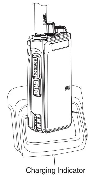 Charging mode
The walkie-talkie is inserted into the charging slot, at which time the charger lights on the red light to indicate that the charging begins, and the green light indicates that the battle cry charging is saturated. (As shown in the picture)
Basic Operation & Functional Introduction
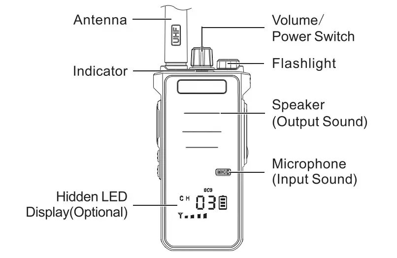
Hidden LED Display Function(Optional)
Hidden LED Display will show you the Channel, battery also CTCSS/DCS code, and signal.
Power on/off
Turn the volume switch potentiometer clockwise to hear the cut sound means the power is on-rotate the volume switch potentio meter counterclockwise. and hear the cut to indicate that the power is off.
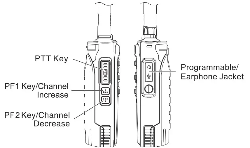
Call
Hold the PTT key launch- the indicator light on the red light, at this time speak to the microphone. your partner will hear you cle early. After speaking, release the PTT key. receive the other party’s information. the green light indicator lights up at the same time.
Increase/Decrease the Volume
When you twist it on clockwise is increases. on the counterclo wise is decreased.
Channel Regulation
Press PF1 /Channel Increase key. channel increase in turn. press PF2/Channel decrease key. channel decline in turn.
Battery Voltage Shortage Reminder
When the walkie-talkie gives a voice prompt, “Please Charge.” When the indicator on a red light. it indicates that the battery voltage is lower than the working voltage. Please charge the walkie-talkie.
Voice Control Turns on
Hold with set sound control PF1 /PF2 side key to turn on VOX function.
the repeated operation to adjust the sound control level. Setting the higher level means the speaker sound you use would be lower. It turns off when you hear a “Dee”.
Monitor Turns on
Press and hold the side key that has the monitor function for 2 seconds to turn on the monitor.
Release key to turn off the monitor function.
Flashlight Turns on
Hold down the side key set in the flashlight function for 2 seconds.
turn on the flashlight. and repeat the operation to turn off the flashlight.
Alarm Function Turns on
Hold down the side key set in the Alarm Function for 2 seconds. turn on the alarm function. And then press the PTT key to turn off the fun action.
Channel Lock
Hold with channel lock function key for 2 seconds. hear “Dee” means turn on the channel lock function. the channel can not be changed at that time. And repeat operation to turn off the function.
Read/Write Frequency Encryption
Available write frequency setting.
Frequency Hopping Function
The frequency hopping function is the digital subtone encryption function of the walkie-talkie. You can choose 4 groups of frequency hopping.
Different frequency hopping can not be interoperable, must be under the same frequency hopping the radio can be interoperable.
CTCSS/DCS
Use software to set the CTCSS/DCS, when the channel set the function, they can talk only when the CTCSS/DCS is the same. If not, the indicator shows green light, but the two users can not talk.
The CTCSS/DCS list is as follows:
CTCSS(Quantity: 50)
| 67.0 | 69. | 72. | 74. | 77.0 | 80. | 83. | 85. | 89. | 92. |
| 95. | 97. | 100.0 | 104. | 107. | 111. | 115. | 119. | 123.0 | 127. |
| 132. | 137. | 141. | 146. | 151. | 157. | 160. | 162. | 166. | 168. |
| 171. | 174. | 177. | 180. | 184. | 186. | 190. | 193. | 197. | 200. |
| 204. | 207. | 211. | 218. | 226. | 229. | 234. | 242. | 250. | 254. |
DCS(Quantity: 116×2)
| D017N | D023N | D025N | D026N | D031N | D032N | D036N | D043N | D047N | DO5ON |
| D051N | D053N | D054N | D055N | D065N | D071N | D072N | D073N | D074N | D114N |
| D115N | D116N | D122N | D125N | D131N | D132N | D134N | D135N | D143N | D145N |
| D152N | D155N | D156N | D162N | D165N | D172N | D174N | D205N | D212N | D217N |
| D223N | D225N | D226N | D243N | D244N | D245N | D246N | D251N | D252N | D254N |
| D255N | D261N | D263N | D265N | D266N | D271N | D274N | D305N | D306N | D311N |
| D315N | D325N | D331N | D332N | D343N | D345N | D346N | D351N | D356N | D364N |
| D365N | D371N | D411N | D412N | D413N | D423N | D425N | D431N | D432N | D445N |
| D446N | D452N | D454N | D455N | D462N | D464N | D465N | D466N | D503N | D506N |
| D516N | D523N | 0526N | D532N | D534N | D546N | D565N | D606N | D612N | D624N |
| D627N | D631N | D632N | D645N | D654N | D662N | D664N | D703N | D712N | D723N |
| D731N | D732N | D734N | D743N | D754N | D765N |
| D0171 | D0231 | D0251 | D0261 | D0311 | D0321 | D0361 | D0431 | D0471 | D0501 |
| D0511 | D0531 | D0541 | D0551 | D0651 | D0711 | D0721 | D0731 | D0741 | D1141 |
| D1151 | D1161 | D122I | D1251 | 1311 | D132I | D134I | D135I | D143I | D145I |
| D152I | D155I | D156I | D162I | D165I | D172I | D1741 | D2051 | D212I | D217I |
| D223I | D225I | D226I | D243I | D244I | D245I | D246I | D251I | D252I | D254I |
| D255I | D261I | D263I | D265I | D266I | D271I | D274I | D3051 | D3061 | D311I |
| D3151 | D325I | D331I | D332I | D343I | D345I | D346I | D3511 | D3561 | D364I |
| D365I | D371I | D411I | D4121 | D413I | D423I | D425I | D4311 | D432I | D445I |
| D446I | D452I | D454I | D455I | D462I | D4641 | D465I | D4661 | D5031 | D5061 |
| D5161 | D523I | D526I | D532I | D5341 | 5461 | D565I | D6061 | D612I | D624I |
| D627I | 6311 | D632I | D645I | D654I | D662I | D664I | 7031 | D712I | D723I |
| D731I | D732I | D734I | D743I | D754I | D765I |
Technical Index
| General | |
| Frequency Range | 420-430MHz / 440-450MHz |
| Channel Capacity | 16 |
| Channel Spacing | 12.5KHz/25KHz |
| Operated Voltage | DC7.4 V |
| Battery | 2800mAh Li-ion Battery |
| Battery Life | (5-5-90 duty cycle)About 8 hours |
| Frequency Stability | ±2.5ppm |
| Operated Temperature | -30c-+60c |
| Antenna Impedance | 50O |
| Dimensions (LxWxH) | 119*54 *37mm(without antenna) |
| Talking Range | Apx 5-8km |
| Power Output | 5W |
FCC Statement
This device complies with Part 15 of the FCC Rules. Operation is subject to the following two conditions:
- This device may not cause harmful interference, and
- this device must accept any interference received, including interference that may cause undesired operation.
NOTE 1: This equipment has been tested and found to comply with the limits for a Class B digital device, pursuant to part 15 of the FCC Rules.
These limits are designed to provide reasonable protection against harmful interference in a residential installation. This equipment generates, uses and can radiate radio frequency energy and, if not installed and used in accordance with the instructions, installed and used in accordance with the instructions, may cause harmful interference to radio communications. However, there is no guarantee that interference will not occur in a particular installation. If this equipment does cause harmful interference to radio or television reception, which can be determined by turning the equipment off and on, the user is encouraged to try to correct the interference by one or more of the following measures:
- Reorient or relocate the receiving antenna.
- Increase the separation between the equipment and receiver.
- Connect the equipment into an outlet on a circuit different from that to which the receiver is connected.
- Consult the dealer or an experienced radio/TV technician for help.
NOTE 2: Any changes or modifications to this unit not expressly approved by the party responsible for compliance could void the user’s authority to operate the equipment.
- This radio is designed for and classified as “Occupational Controlled Use Only”, meaning it must be used only during the course of employment by individuals aware of the hazards, and the ways to minimize such hazards; NOT intended for use in a General population uncontrolled environment.
- DO NOT operate the radio without a proper antenna attached, as this may damage the radio and may also cause you to exceed RF exposure limits. A proper antenna is an antenna supplied with this radio by the manufacturer or an antenna specifically authorized by the manufacturer for use with this radio.
- DO NOT transmit for more than 50% of total radio use time, more than 50% of the time can cause RF exposure compliance requirements to be exceeded.
- This transmitter may operate with the antenna(s) documented in this filing in Push-to-Talk and body-worn configurations. RF exposure compliance is limited to the specific belt-clip and accessory configurations as documented in this filing and the separation distance between the user and the device or its antenna shall be at least 2.5 cm.
Warranty Card
Model Number:……………………………………….
Serial Number:………………………………………
Purchasing Late:………………………………………
Dealer:………………………………………
Telephone:………………………………………
User’s Name:………………………………………
Telephone:………………………………………
Address:………………………………………
ZIP Code:………………………………………
Warranty instructions:
- This warranty card shall be kept by the customer as a warranty certificate and will not be made up for the loss.
- This card must be covered by the point of sale and the date of completion before it can take effect.
- This card may not be modified, please confirm that the warranty card serial number is consistent with the purchase radio number, otherwise, it is invalid.
- The warranty period is one year, chargers, batteries, earphones, antennas, and feeders are consumables and are not covered by warranty.
- Users can choose the following channels to obtain maintenance services:
a. Handle it at the original purchase office.
b. Our company is at the local special maintenance point.


