
Aeotec
MultiSensor 7
SKU: AEOEZWA024


Quickstart
This is a
secure
Alarm Sensor
for
Europe.
To run this device please insert fresh 2 * CR123A batteries.
Please make sure the internal battery is fully charged.
If your Z-Wave gateway supports SmartStart, you can scan the QR code on the MultiSensor 7 to automatically pair the sensor if your Z-Wave hub supports this.
Important safety information
Please read this manual carefully. Failure to follow the recommendations in this manual may be dangerous or may violate the law.
The manufacturer, importer, distributor and seller shall not be liable for any loss or damage resulting from failure to comply with the instructions in this manual or any other material.
Use this equipment only for its intended purpose. Follow the disposal instructions.
Do not dispose of electronic equipment or batteries in a fire or near open heat sources.
What is Z-Wave?
Z-Wave is the international wireless protocol for communication in the Smart Home. This
device is suited for use in the region mentioned in the Quickstart section.

Z-Wave ensures a reliable communication by reconfirming every message (two-way
communication) and every mains powered node can act as a repeater for other nodes
(meshed network) in case the receiver is not in direct wireless range of the
transmitter.
This device and every other certified Z-Wave device can be used together with any other
certified Z-Wave device regardless of brand and origin as long as both are suited for the
same frequency range.
If a device supports secure communication it will communicate with other devices
secure as long as this device provides the same or a higher level of security.
Otherwise it will automatically turn into a lower level of security to maintain
backward compatibility.
For more information about Z-Wave technology, devices, white papers etc. please refer
to www.z-wave.info.
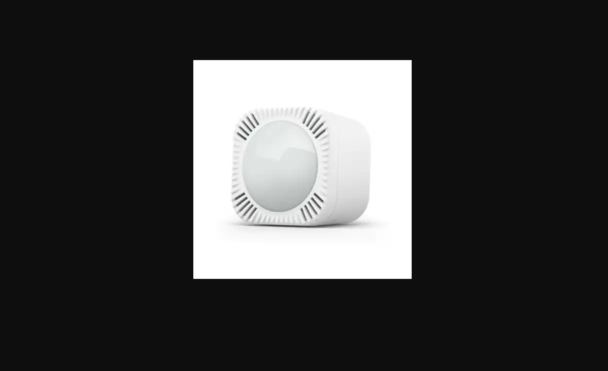
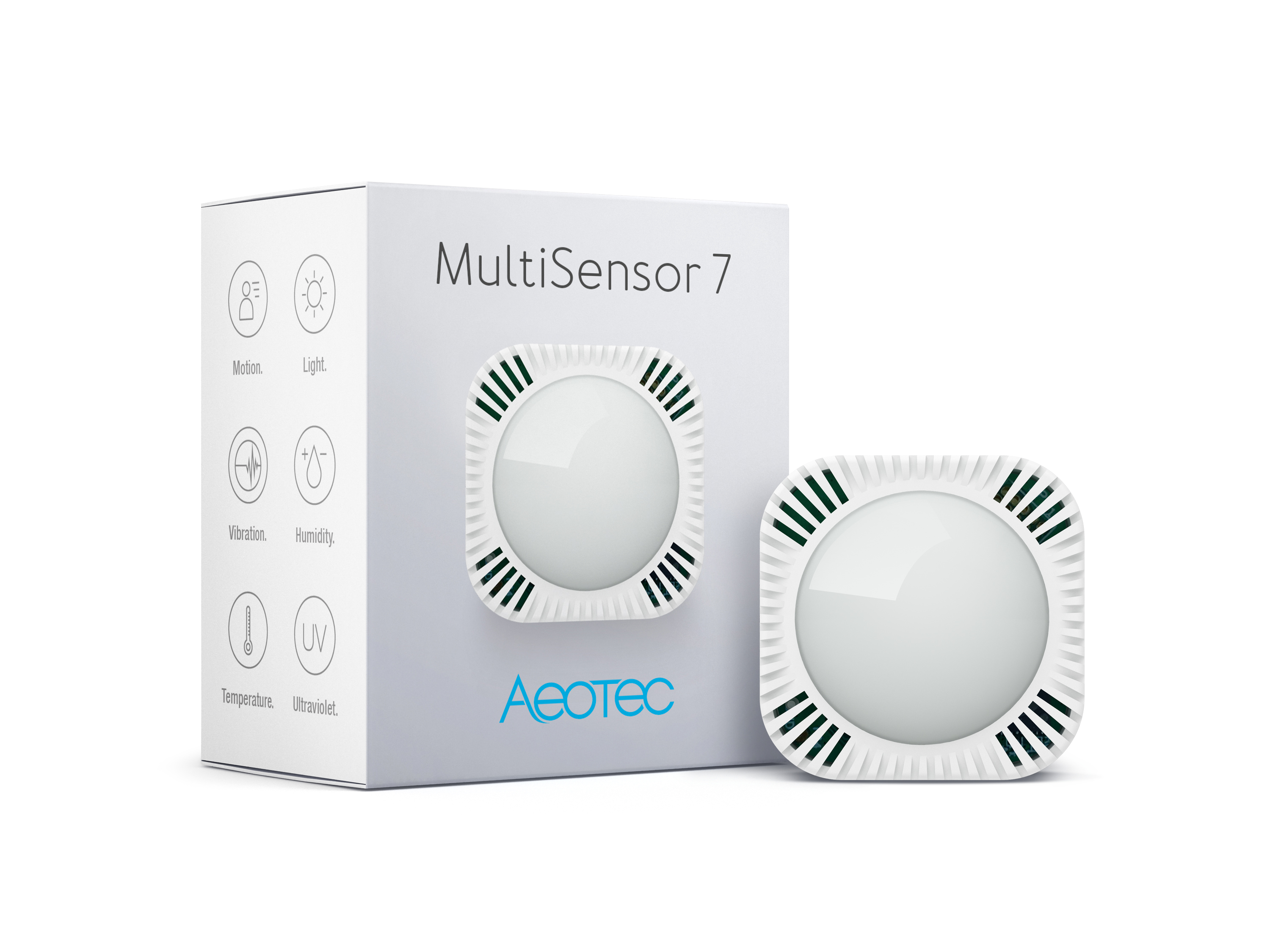
Product Description
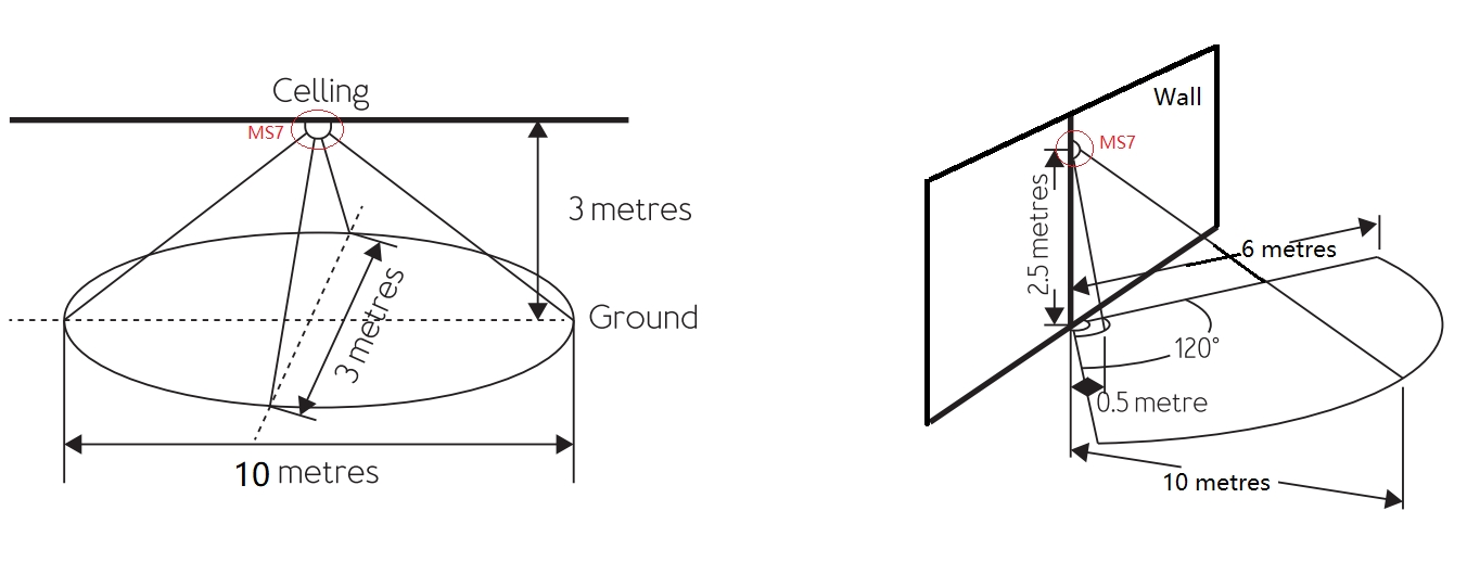
Aeotec MultiSensor 7 was developed to detect ambient values and movement and to transmit them with Z-Wave Plus. It is powered by Aeotec’s Gen7 technology. You can find out more about MultiSensor 7 by following that link.
Prepare for Installation / Reset
Please read the user manual before installing the product.
In order to include (add) a Z-Wave device to a network it must be in factory default
state. Please make sure to reset the device into factory default. You can do this by
performing an Exclusion operation as described below in the manual. Every Z-Wave
controller is able to perform this operation however it is recommended to use the primary
controller of the previous network to make sure the very device is excluded properly
from this network.
Reset to factory default
This device also allows to be reset without any involvement of a Z-Wave controller. This
procedure should only be used when the primary controller is inoperable.
Press and hold the button for 20 seconds. When the red led flashes, the device will enter the factory reset mode.
Safety Warning for Batteries
The product contains batteries. Please remove the batteries when the device is not used.
Do not mix batteries of different charging level or different brands.
Installation
Determine the power type you want to use.
MultiSensor 7 can be a sleeping battery device or a repeater as a USB-powered device. Make sure you select your preferred power type before you start pairing.
Note – Any time you change the input power type (ie. Battery to USB power), you should re-include as your Z-Wave hub will only understand if it is a sleeping device or a Repeater device upon its first pair into your controller.
For a USB powered installation (acts as a repeater when paired on USB power):
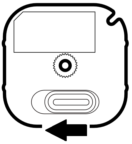
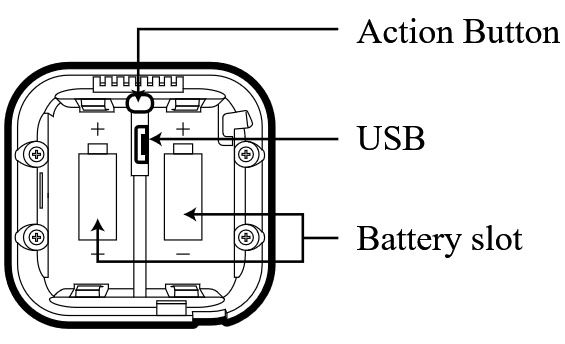
1. Remove the battery cover by sliding the Unlock button LEFT, then pull the cover off.
2. Insert the MicroUSB of the provided USB cable into your sensor‘s MicroUSB port.
3. Insert the larger end of the USB cable into a computer or any 5V adapter which will immediately power your MultiSensor 7.
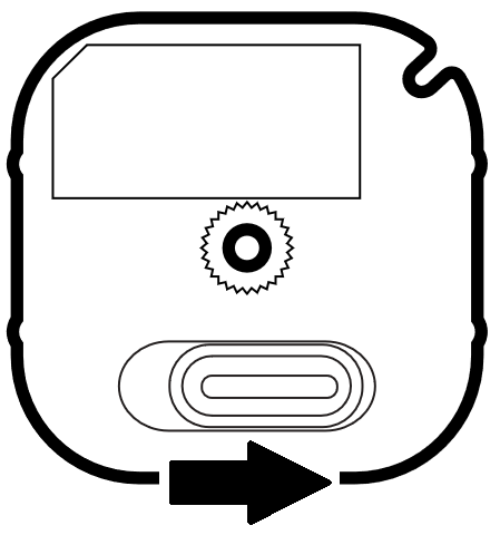
4. Make sure to seat the Battery Cover back onto the MultiSensor 7 and lock it in by sliding the Unlock button RIGHT.
For a battery-powered installation (acts as a sleeping device when paired on battery power):
1. Remove the battery cover by sliding the Unlock button LEFT, then pull the cover off.
2. Insert two CR123A lithium batteries orientated according to the diagram within your sensor.
Try inserting the batteries flat rather than at an angle.
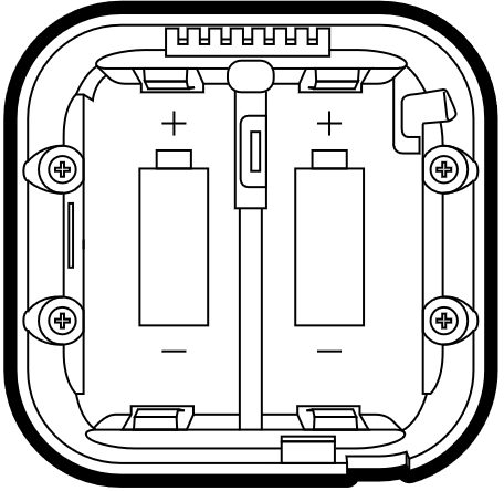
Note: MultiSensor 7 can be powered by a single CR123A (doesn‘t matter which port), though batteries will require changing more frequently (half the expected battery life).
WARNING: Not compatible with rechargeable CR123A batteries (3.6V).
3. Make sure to seat the Battery Cover back onto the MultiSensor 7 and lock it in by sliding the Unlock button RIGHT.
To install your TriSensor with the Back-Mount Plate;
1. You can affix the Back-Mount Arm by Double-Sided Tape or using the provided KA2.5ƒ-20 mm screws.
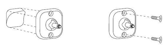
Tips: We suggest you choose the second method (using screws to affix the Back-Mount Arm) which would be more stable.
2. After you have completed the affixing of Back-Mount Arm, you will need to lock TriSensor to the Back-Mount Arm by screwing TriSensor in.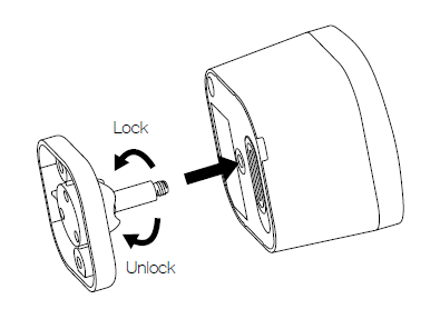
3. The Back-Mount Arm may be locked at various angles by turning the Friction Lock clockwise and counter-clockwise to respectively tighten or loosen the angle of the arm. You can rotate the Friction Lock to change the measurement area of sensor.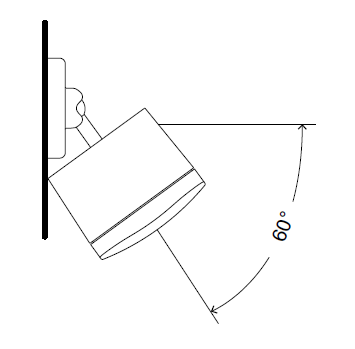
Inclusion/Exclusion
On factory default the device does not belong to any Z-Wave network. The device needs
to be added to an existing wireless network to communicate with the devices of this network.
This process is called Inclusion.
Devices can also be removed from a network. This process is called Exclusion.
Both processes are initiated by the primary controller of the Z-Wave network. This
controller is turned into exclusion respective inclusion mode. Inclusion and Exclusion is
then performed doing a special manual action right on the device.
Inclusion
1. Open the Cover
2. Insert the battery or connect the USB cable
3. Press the button once
4. If prompted, enter the 5 digit DSK code.
Exclusion
1. Open the Cover
2. Press the button once
Product Usage
Button Functions.
| Action button press | LED Status | Function |
| 1x Tap (when factory reset) | Solid Yellow | Pair Mode Enters Z-Wave pair mode, flashes white/green 4 times within 2 seconds upon success. |
| 1x Tap (when already paired) | Solid Purple | Sends NIF / Excludes device if Z-Wave controller is in unpair mode, starts blue LED fade in/out if unpaired and factory reset successfully. |
| Press and hold [1, 2 seconds) | No LED | N/A |
| Press and hold [2, 5 seconds) | Solid Red | Quick Wakeup LED will disappear as soon as you release its button. The MultiSensor 7 will send a wakeup report to your Z-Wave Controller to take in any queued z-wave commands waiting in your controller. |
| Press and hold [5, 9 seconds) | Solid Orange | Long Wakeup Mode LED will remain solid Orange upon release of its button for 5 minutes maximum (or until told to sleep by user or z-wave controller). This will allow you to easily configure this device while the sensor is used with battery power assuming your Z-Wave controller does not queue the command. |
| Press and hold [9, 15 seconds) | Solid Cyan | Communication Health Test (Direct gateway communication – does not test through repeaters). This will test your MultiSensor 7 direct communication to your Z-Wave Controller. It will remain Cyan while it is testing. Once finished it will become a solid color for 2 seconds as red, yellow, or green to indicate health: Red = Bad health, can‘t communicate at all. |
| Press and hold [15, 20 seconds) | Blinking Red | Release here to cancel Factory Reset. |
| Press and hold [20+ seconds) | Blue fade in/out for 2 seconds. | Factory Reset. |
Communication to a Sleeping device (Wakeup)
This device is battery operated and turned into deep sleep state most of the time
to save battery life time. Communication with the device is limited. In order to
communicate with the device, a static controller C is needed in the network.
This controller will maintain a mailbox for the battery operated devices and store
commands that can not be received during deep sleep state. Without such a controller,
communication may become impossible and/or the battery life time is significantly
decreased.
This device will wakeup regularly and announce the wakeup
state by sending out a so called Wakeup Notification. The controller can then
empty the mailbox. Therefore, the device needs to be configured with the desired
wakeup interval and the node ID of the controller. If the device was included by
a static controller this controller will usually perform all necessary
configurations. The wakeup interval is a tradeoff between maximal battery
life time and the desired responses of the device. To wakeup the device please perform
the following action:
In order to configure Multisensor 7, you must either (1) wake up Multisensor 7 using the below button press function, or (2) temporarily put your Multisensor 7 on USB power.
This section will go over the manual wakeup of this sensor in case you don‘t want to wait for configuration.
Quick Wakeup.
1. Press and hold Multisensor 7 Action button
2. Wait until the LED turns into a Red Color (1 – 2 seconds)
3. Release Multisensor 7 Action Button, the LED should turn off right away. Any queued commands in your Z-Wave Controller will be sent over.
Long Wakeup.
1. Press and hold Multisensor 7 Action button
2. Wait until the LED turns into a solid orange color (2 – 5 seconds)
3. Release Multisensor 7 Action Button, the LED should remain solid orange while it is awake. Send any configurations from your hub (assuming the commands are not queued).
- If the MultiSensor 7 LED orange LED turns off right away, this would indicate that your hub is putting your device to sleep. Try un-powering your hub temporarily, follow steps 1-3 again, then power up your hub again.
4. Tap the Action Button on Multisensor 7 to put Multisensor 7 back to sleep, or wait 5 minutes. (recommended to manually put it back to sleep to conserve battery life).
Quick trouble shooting
Here are a few hints for network installation if things dont work as expected.
- Make sure a device is in factory reset state before including. In doubt exclude before include.
- If inclusion still fails, check if both devices use the same frequency.
- Remove all dead devices from associations. Otherwise you will see severe delays.
- Never use sleeping battery devices without a central controller.
- Dont poll FLIRS devices.
- Make sure to have enough mains powered device to benefit from the meshing
Association – one device controls an other device
Z-Wave devices control other Z-Wave devices. The relationship between one device
controlling another device is called association. In order to control a different
device, the controlling device needs to maintain a list of devices that will receive
controlling commands. These lists are called association groups and they are always
related to certain events (e.g. button pressed, sensor triggers, …). In case
the event happens all devices stored in the respective association group will
receive the same wireless command wireless command, typically a ‘Basic Set’ Command.
Association Groups:
Group NumberMaximum NodesDescription
| 1 | 5 | Lifeline |
| 2 | 5 | Basic Set Command will be sent to the associated device when motion trigger or untrigger. The basic set value is determined by Param11, Param12. See Param13 for more information. |
| 3 | 5 | Basic Set: When the temperature change value is over or under the threshold set by Param16. Scale is determined by Param64. |
| 4 | 5 | Basic Set: When the temperature change value is under or over the threshold set by Param17. Scale is determined by Param64. |
| 5 | 5 | Basic Set: When the current humidity is over or under the threshold set by Param14 |
| 6 | 5 | Basic Set: When the current humidity is under or over the threshold set by Param15 |
| 7 | 5 | Basic Set: When the current light/lux is over or under the threshold set by Param18 |
| 8 | 5 | Basic Set: When the current light/lux is under or over the threshold set by Param19. |
| 9 | 5 | Basic Set: When the current UV is over or under the threshold set by Param20 |
| 10 | 5 | Basic Set: When the current UV is under or over the threshold set by Param21 |
| 11 | 5 | Sensor Multilevel Report: When sensors above over limit or below under limit. |
Configuration Parameters
Z-Wave products are supposed to work out of the box after inclusion, however
certain configuration can adapt the function better to user needs or unlock further
enhanced features.
IMPORTANT: Controllers may only allow configuring
signed values. In order to set values in the range 128 … 255 the value sent in
the application shall be the desired value minus 256. For example: To set a
parameter to 200 it may be needed to set a value of 200 minus 256 = minus 56.
In case of a two byte value the same logic applies: Values greater than 32768 may
needed to be given as negative values too.
Parameter 1: Beaming Enable/Disable
Used to enable/disable beaming.If set to 1, FLiRs commands will be supported. But the device must be re-included into the network to activate it.
Size: 1 Byte, Default Value: 1
SettingDescription
| 0 | Disable |
| 1 | Enable |
Parameter 2: Motion Retrigger Time
Presence re-detection time set in second to allow motion sensor to reset timeout of motion sensor. In this time, the motion sensor can not be triggered again. If this value reach zero, the timeout configuration value set by Param3 will be reset. This setting value must always be less than timeout configuration.0 – disable1~3600 – timeout set in seconds
Size: 2 Byte, Default Value: 30
SettingDescription
| 30 – 3600 | timeout set in seconds |
Parameter 3: Motion Untrigger Time
Timeout configuration set in second for motion sensor to send no trigger status.
Size: 2 Byte, Default Value: 240
SettingDescription
| 30 – 3600 | timeout set in seconds |
Parameter 4: Motion Sensitivity
Set the sensitivity of motion sensor.
Size: 1 Byte, Default Value: 11
SettingDescription
| 0 | Disable |
| 1 – 11 | sensitivity range |
Parameter 5: Motion Report Type
Set which command class will be sent when the motion sensor is triggered or detriggered.
Size: 1 Byte, Default Value: 2
SettingDescription
| 0 | Sends Notification Report |
| 1 | Sends Sensor Binary Report |
| 2 | Sends Notification and Sensor Binary Report |
Parameter 6: Vibration Sensor Enable/Disable
Used to enable/disable vibration sensor.
Size: 1 Byte, Default Value: 255
SettingDescription
| 0 | disable vibration |
| 1 – 254 | timeout set in minutes to reset vibration status |
| 255 | timeout set in minutes to reset vibration status |
Parameter 7: Vibration Intensity Reports
Used to enable/disable vibration intensity reports. If set to 1, vibration intensity will be sent to gateway when triggered.
Size: 1 Byte, Default Value: 0
SettingDescription
| 0 | Disable |
| 1 | Enable |
Parameter 9: Wakeup CC Timeout
Timeout set in seconds after Wakeup CC is send out before go to sleep. If wakeup no more information received, return to sleep mode immediately.
Size: 1 Byte, Default Value: 15
SettingDescription
| 0 – 255 | Timeout set in seconds |
Parameter 10: Power Status
This value is Readonly. Used to report the power status (USB or Battery powered) The device must be re-included in the network to change the role type.
Size: 1 Byte, Default Value: 0
SettingDescription
| 0 | When battery powered, the device will act as RSS. |
| 1 | When USB cable insert, the device will act as LSS. |
Parameter 11: Motion Group Control(Group2)
Set control of other devices on group2 based on motion trigger.
Size: 1 Byte, Default Value: 0
SettingDescription
| 0 | Send BASIC_SET (0xFF) when motion is triggered to associated device Send BASIC_SET (0x00) when motion is untriggered to associated device |
| 1 | Send BASIC_SET (0x00) when motion is triggered Send BASIC_SET (0xFF) when motion is untriggered |
| 2 | Send BASIC_SET (0xFF) when motion is triggered, Nothing when motion untriggered. |
| 3 | Send BASIC_SET (0x00) when motion is triggered, Nothing when motion untriggered. |
| 4 | Send BASIC_SET (0x00) when motion is untriggered, Nothing when motion triggered. |
| 5 | Send BASIC_SET (0xFF) when motion is untriggered, Nothing when motion triggered. |
| 6 | Send BASIC_SET (value is configured by parameter 12) when motion is triggered to associated devices. Send BASIC_SET (value is configured by parameter 12) when motion is untriggered. |
Parameter 12: Motion Group Value Setting
Set Basic Set value for Group2. The MSB will act as the basic set value when motion trigger. The LSB will act as the basic set value when motion untrigger. E.g. value=0x0A00, then BASIC_SET(0x0A) will be sent when motion trigger, BASIC_SET(0x00) will be sent when motion untrigger.
Size: 2 Byte, Default Value: 65280
SettingDescription
| 0 – 65535 | Set Basic Set value for Group2. |
Parameter 13: Motion Group Control Requirement
Set threshold of Light/Lux when devices associated in group2 should be triggered by motion. Associated device only receive BASIC_SET command when light
Size: 2 Byte, Default Value: 30000
SettingDescription
| 0 – 30000 | Set threshold of Light/Lux |
Parameter 14: Over Humidity Group Threshold (Group5)
Set threshold of humidity. If measured humidity >= (this value), send BASIC_SET (0xFF) to associated devices through group5. If measured humidity < (this value) send BASIC_SET (0x00) to associated devices through group5.
Size: 1 Byte, Default Value: 60
SettingDescription
| 0 – 100 | Set threshold of humidity. |
Parameter 15: Under Humidity Group Threshold (Group6)
Set threshold of humidity. If measure humidity(this value) send BASIC_SET (0x00) to associated devices through group6.
Size: 1 Byte, Default Value: 40
SettingDescription
| 0 – 100 | Set threshold of humidity. |
Parameter 16: Over Heat Group Threshold (Group3)
Set threshold of temperature. Designed to control Air Conditioners or temperature controllers ON or OFF. If measured temperature >= (this value, Scale is determined by Param64) send BASIC_SET (0xFF) to associated devices. If measured temperature<(this value) send BASIC_SET (0x00) to associated devices. E.g. Value 239 means 23.9 C. Value 750 means 75.0 F.
Size: 2 Byte, Default Value: 239
SettingDescription
| -400 – 850 | Set threshold of temperature |
Parameter 17: Under Heat Group Threshold (Group4)
Set threshold of temperature. Designed to control Air Conditioners or temperature controllers ON or OFF. If measured temperature(this value) send BASIC_SET (0x00) to associated devices. E.g. Value 155 means 15.5 C. Value 600 means 60.0 F.
Size: 2 Byte, Default Value: 155
SettingDescription
| -400 – 850 | Set threshold of temperature |
Parameter 18: Over Light Group Threshold (Group7)
Set threshold of Light/Lux. If measured light/lux >= (this value) send BASIC_SET (0xFF) to associated devices. If measured light/lux < (this value) send BASIC_SET (0x00) to associated devices.
Size: 2 Byte, Default Value: 2000
SettingDescription
| 0 – 30000 | Set threshold of Light/Lux. |
Parameter 19: Under Light Group Threshold (Group8)
Set threshold of Light/Lux. If measured light/lux(this value) send BASIC_SET (0x00) to associated devices.
Size: 2 Byte, Default Value: 100
SettingDescription
| 0 – 30000 | Set threshold of Light/Lux. |
Parameter 20: Over UV Group Threshold (Group9)
Set threshold of UV. If measured UV >= (this value) send BASIC_SET (0xFF) to associated devices. If measured UV < (this value) send BASIC_SET (0x00) to associated devices.
Size: 1 Byte, Default Value: 8
SettingDescription
| 0 | Set threshold of UV. |
Parameter 21: Under UV Group Threshold (Group10)
Set threshold of UV. If measured UV(this value) send BASIC_SET (0x00 to associated devices.)
Size: 1 Byte, Default Value: 1
SettingDescription
| 0 – 11 | Set threshold of UV. |
Parameter 39: Low Battery Threshold
Configure low battery report threshold, sends low battery report via notification and battery report when battery level drops under setting. Unit %.
Size: 1 Byte, Default Value: 50
SettingDescription
| 10 – 90 | Configure low battery report threshold |
Parameter 40: Threshold Check Enable/Disable
Enable/Disable threshold reporting, check time can be adjusted by Param45.
Size: 1 Byte, Default Value: 0
SettingDescription
| 0 | disable all threshold reports |
| 1 | enable all threshold reports |
Parameter 41: Temperature Threshold
Threshold = (Value * 0.1) Scale is determined by Param64.
Size: 1 Byte, Default Value: 10
SettingDescription
| 0 – 255 | Threshold = (Value * 0.1) Scale is determined by Param64. 0 = disable. |
Parameter 42: Humidity Threshold
Humidity range = 1% to 50%,
Size: 1 Byte, Default Value: 5
SettingDescription
| 0 – 50 | Humidity range = 1% to 50%, 0 = disable. |
Parameter 43: Lux Threshold
Size: 2 Byte, Default Value: 250
SettingDescription
| 0 – 10000 | Lux Threshold 0 = disabled |
Parameter 44: UV Threshold
Size: 1 Byte, Default Value: 1
SettingDescription
| 0 – 11 | UV Threshold 0 = disabled |
Parameter 45: Threshold Check Time
Set threshold check time in seconds if the threshold is enabled via Parameter 40.
Size: 2 Byte, Default Value: 240
SettingDescription
| 1 – 65535 | Set threshold check time in seconds when USB powered |
| 60 – 65535 | Set theshould check time in secons when Battery powered |
Parameter 46: Low Temperature Report
Enable/Disable alarm report for low temperature
Size: 1 Byte, Default Value: 1
SettingDescription
| 0 | Disable |
| 1 | Enable |
Parameter 48: Sensor Limit Control
Used to enable/disable measurement reports for various sensors that is more than the upper limit value or less than the lower limit value.
Size: 1 Byte, Default Value: 0
SettingDescription
| 0 | Disable |
| 1 | Temperature upper level |
| 2 | Humidity upper level |
| 4 | Lux upper level |
| 8 | UV upper level |
| 16 | Temperature lower level |
| 32 | Humidity lower level |
| 64 | Lux lower level |
| 128 | UV lower level |
Parameter 49: Temperature Upper Limit
Set upper limit level for temperature set in scale of 0.1. Scale is determined by Param64. If (Current measurement) > (Upper Limit), then report sensor.
Size: 2 Byte, Default Value: 280
SettingDescription
| -400 – 1000 | Set upper limit level for temperature |
Parameter 50: Temperature Lower Limit
Set lower limit level for temperature set in scale of 0.1. Scale is determined by Param64. If (Current Measurement) < (Lower limit), then report sensor.
Size: 2 Byte, Default Value: 0
SettingDescription
| -400 – 1000 | Set lower limit level for temperature |
Parameter 51: Temperature Recover Limit
Temperature recover limit set in scale of 0.1. Scale is determined by Param64. If (Current measurement) = (lower limit + recover limit), then temperature report.
Size: 1 Byte, Default Value: 20
SettingDescription
| 1 – 255 | Temperature recover limit set in scale of 0.1. |
Parameter 52: Humidity Upper Limit
Set humidity upper limit level.
Size: 1 Byte, Default Value: 60
SettingDescription
| 0 – 100 | Set humidity upper limit level. |
Parameter 53: Humidity Lower Limit
Set humidity lower limit level
Size: 1 Byte, Default Value: 40
SettingDescription
| 0 – 100 | Set humidity lower limit level |
Parameter 54: Humidity Recover Limit
Set humidity recover limit level. Refer to Param 51.
Size: 1 Byte, Default Value: 5
SettingDescription
| 1 – 50 | Set humidity recover limit level |
Parameter 55: Lux Upper Limit
Set lux upper limit level.
Size: 2 Byte, Default Value: 1000
SettingDescription
| 0 – 30000 | Set lux upper limit level. |
Parameter 57: Lux Recover Limit
Set lux recover limit level. Refer to Param 51.
Size: 1 Byte, Default Value: 100
SettingDescription
| 1 – 255 | Set lux recover limit level. |
Parameter 58: UV Upper Limit
Set UV upper limit level.
Size: 1 Byte, Default Value: 8
SettingDescription
| 1 – 11 | Set UV upper limit level. |
Parameter 59: UV Lower Limit
Set UV lower limit level.
Size: 1 Byte, Default Value: 4
SettingDescription
| 1 – 11 | Set UV lower limit level. |
Parameter 60: UV Recover Limit
Set UV recover limit level. Refer to Param 51.
Size: 1 Byte, Default Value: 1
SettingDescription
| 1 – 5 | Set UV recover limit level. |
Parameter 61: Out-of-limit State
This is read only and bit mask. Out of the limit state of sensors.
Size: 1 Byte, Default Value: 0
SettingDescription
| 0 | within limit |
| 1 | Temperature upper level |
| 2 | Humidity upper level |
| 4 | Lux upper level |
| 8 | UV upper level |
| 16 | Temperature lower level |
| 32 | Humidity lower level |
| 64 | Lux lower level |
| 128 | UV lower level |
Parameter 64: Temperature Scale
Set the scale for temperature when reports.
Size: 1 Byte, Default Value: 0
SettingDescription
| 0 | Celsius |
| 1 | Fahrenheit |
Parameter 81: LED Activity
Allow user to enable/disable LED activity of specific reports sent by sensor. Button press indicator is not affected by this.
Size: 1 Byte, Default Value: 1
SettingDescription
| 0 | disable |
| 1 | enable |
Parameter 82: Motion Sensor Report Indicator
If LED is enabled by Param81, allow user to change the report color of motion sensor.
Size: 1 Byte, Default Value: 3
SettingDescription
| 0 | Disable |
| 1 | Red |
| 2 | Blue |
| 3 | Green |
| 4 | Pink |
| 5 | Cyan |
| 6 | Purple |
| 7 | Orange |
| 8 | Yellow |
| 9 | White |
Parameter 83: Temperature Sensor Report Indicator
If LED is enabled by Param81, allow user to change the report color of temperature sensor.
Size: 1 Byte, Default Value: 0
SettingDescription
| 0 | Disable |
| 1 | Red |
| 2 | Blue |
| 3 | Green |
| 4 | Pink |
| 5 | Cyan |
| 6 | Purple |
| 7 | Orange |
| 8 | Yellow |
| 9 | White |
Parameter 84: Humidity Sensor Report Indicator
If LED is enabled by Param81, allow user to change the report color of humidity sensor.
Size: 1 Byte, Default Value: 0
SettingDescription
| 0 | Disable |
| 1 | Red |
| 2 | Blue |
| 3 | Green |
| 4 | Pink |
| 5 | Cyan |
| 6 | Purple |
| 7 | Orange |
| 8 | Yellow |
| 9 | White |
Parameter 85: Lux Sensor Report Indicator
If LED is enabled by Param81, allow user to change the report color of Lux sensor.
Size: 1 Byte, Default Value: 0
SettingDescription
| 0 | Disable |
| 1 | Red |
| 2 | Blue |
| 3 | Green |
| 4 | Pink |
| 5 | Cyan |
| 6 | Purple |
| 7 | Orange |
| 8 | Yellow |
| 9 | White |
Parameter 86: UV Sensor Report Indicator
If LED is enabled by Param81, allow user to change the report color of UV sensor.0 – Disabled1 – Red2 – Blue3 – Green4 – Pink5 – Cyan6 – Purple7 – Orange8 – Yellow9 – White
Size: 1 Byte, Default Value: 0
SettingDescription
| 0 | Disable |
| 1 | Red |
| 2 | Blue |
| 3 | Green |
| 4 | Pink |
| 5 | Cyan |
| 6 | Purple |
| 7 | Orange |
| 8 | Yellow |
| 9 | White |
Parameter 87: Vibration Sensor Report Indicator
If LED is enabled by Param81, allow user to change the report color of vibration sensor.
Size: 1 Byte, Default Value: 2
SettingDescription
| 0 | Disable |
| 1 | Red |
| 2 | Blue |
| 3 | Green |
| 4 | Pink |
| 5 | Cyan |
| 6 | Purple |
| 7 | Orange |
| 8 | Yellow |
| 9 | White |
Parameter 88: Battery Report Indicator
If LED is enabled by Param81, allow user to change the report color of battery.
Size: 1 Byte, Default Value: 0
SettingDescription
| 0 | Disable |
| 1 | Red |
| 2 | Blue |
| 3 | Green |
| 4 | Pink |
| 5 | Cyan |
| 6 | Purple |
| 7 | Orange |
| 8 | Yellow |
| 9 | White |
Parameter 89: Wakeup Report Indicator
If LED is enabled by Param81, allow user to change the report color of wakeup.
Size: 1 Byte, Default Value: 8
SettingDescription
| 0 | Disable |
| 1 | Red |
| 2 | Blue |
| 3 | Green |
| 4 | Pink |
| 5 | Cyan |
| 6 | Purple |
| 7 | Orange |
| 8 | Yellow |
| 9 | White |
Parameter 90: Communication Indicator
If LED is enabled by Param81, allow user to change indicator color when receiving communication from gateway or other devices.
Size: 1 Byte, Default Value: 0
SettingDescription
| 0 | Disable |
| 1 | Red |
| 2 | Blue |
| 3 | Green |
| 4 | Pink |
| 5 | Cyan |
| 6 | Purple |
| 7 | Orange |
| 8 | Yellow |
| 9 | White |
Parameter 101: Automatic Report Checklist 1
Checklist 1 for automatic timed report. When the corresponding item is selected, it will be checked when timeout setting by Param111.
Size: 1 Byte, Default Value: 241
SettingDescription
| 1 | Battery |
| 16 | UV |
| 32 | Temperature |
| 64 | Humidity |
| 128 | Lux |
Parameter 102: Automatic Report Checklist 2
Checklist 2 for automatic timed report. When the corresponding item is selected, it will be checked when timeout setting by Param112.
Size: 1 Byte, Default Value: 0
SettingDescription
| 1 | Battery |
| 16 | UV |
| 32 | Temperature |
| 64 | Humidity |
| 128 | LUX |
Parameter 103: Automatic Report Checklist 3
Checklist 3 for automatic timed report. When the corresponding item is selected, it will be checked when timeout setting by Param113.
Size: 1 Byte, Default Value: 0
SettingDescription
| 1 | Battery |
| 16 | UV |
| 32 | Temperature |
| 64 | Humidity |
| 128 | LUX |
Parameter 111: Automatic Checklist 1 Interval Time
Interval time set in seconds to check the checklist1s items. Multilevel Sensor Report will be sent when timeout.
Size: 2 Byte, Default Value: 3600
SettingDescription
| 30 – 65535 | Interval time set in seconds |
Parameter 112: Automatic Checklist 2 Interval Time
Interval time set in seconds to check the checklist2s items. Multilevel Sensor Report will be sent when timeout.
Size: 2 Byte, Default Value: 3600
SettingDescription
| 30 – 65535 | Interval time set in seconds |
Parameter 113: Automatic Checklist 3 Interval Time
Interval time set in seconds to check the checklist3s items. Multilevel Sensor Report will be sent when timeout.
Size: 2 Byte, Default Value: 3600
SettingDescription
| 30 – 65535 | Interval time set in seconds |
Parameter 201: Temperature Offset Value
Can add or minus this setting value to calibrate temperature when checked. Scale is defined by Param64. e.g. Value 15 means 1.5C or 1.5F.
Size: 2 Byte, Default Value: 0
SettingDescription
| -200 – 200 | Temperature Offset Value |
Parameter 202: Humidity Offset Value
Can add or minus this setting value to calibrate humidity when checked. Unit: %.
Size: 1 Byte, Default Value: 0
SettingDescription
| -100 – 100 | Humidity Offset Value |
Parameter 203: Lux Offset Value
Can add or minus this setting value to calibrate Lux when checked.
Size: 2 Byte, Default Value: 0
SettingDescription
| -10000 – 10000 | Lux Offset Value |
Parameter 204: UV Offset Value
Can add or minus this setting value to calibrate UV when checked.
Size: 1 Byte, Default Value: 0
SettingDescription
| -10 – 10 | Offset Value range -10-10. |
Technical Data
| Dimensions | 45 x 45 x 40 mm |
| Weight | 65 gr |
| Hardware Platform | ZGM130 |
| EAN | 1220000016873 |
| IP Class | IP 20 |
| Voltage | 3V |
| Battery Type | 2 * CR123A |
| Device Type | Notification Sensor |
| Network Operation | Always On Slave |
| Z-Wave Version | 7.12.2 |
| Certification ID | ZC12-20120147 |
| Z-Wave Product Id | 0x0371.0x0002.0x0018 |
| Firmware Updatable | Updatable by Consumer by RF |
| Color | White |
| Frequency | Europe – 868,4 Mhz |
| Maximum transmission power | 5 mW |
Supported Command Classes
- Application Status
- Association Grp Info V3
- Association V2
- Battery
- Configuration V4
- Device Reset Locally
- Firmware Update Md V5
- Indicator V3
- Manufacturer Specific V2
- Multi Channel Association V3
- Notification V8
- Powerlevel
- Security
- Security 2
- Sensor Binary V2
- Sensor Multilevel V11
- Supervision
- Transport Service V2
- Version V3
- Wake Up V2
- Zwaveplus Info V2
Explanation of Z-Wave specific terms
- Controller — is a Z-Wave device with capabilities to manage the network.
Controllers are typically Gateways,Remote Controls or battery operated wall controllers. - Slave — is a Z-Wave device without capabilities to manage the network.
Slaves can be sensors, actuators and even remote controls. - Primary Controller — is the central organizer of the network. It must be
a controller. There can be only one primary controller in a Z-Wave network. - Inclusion — is the process of adding new Z-Wave devices into a network.
- Exclusion — is the process of removing Z-Wave devices from the network.
- Association — is a control relationship between a controlling device and
a controlled device. - Wakeup Notification — is a special wireless message issued by a Z-Wave
device to announces that is able to communicate. - Node Information Frame — is a special wireless message issued by a
Z-Wave device to announce its capabilities and functions.


